Language selection

Search

Patent 2173799 Summary

Third-party information liability

Some of the information on this Web page has been provided by external sources. The Government of Canada is not responsible for the accuracy, reliability or currency of the information supplied by external sources. Users wishing to rely upon this information should consult directly with the source of the information. Content provided by external sources is not subject to official languages, privacy and accessibility requirements.

Claims and Abstract availability

Any discrepancies in the text and image of the Claims and Abstract are due to differing posting times. Text of the Claims and Abstract are posted:

  • At the time the application is open to public inspection;
  • At the time of issue of the patent (grant).
(12) Patent: (11) CA 2173799
(54) English Title: RACK SYSTEM FOR SUPPORTING ELECTRONIC EQUIPMENT
(54) French Title: SUPPORT MODULAIRE POUR MATERIEL ELECTRONIQUE
Status: Deemed expired
Bibliographic Data
Abstracts

English Abstract


A modular rack system is provided for supporting
electronic equipment, comprising vertical and lateral frame
members cooperating to form a vertical supporting frame,
and shelf or rack members supported from a front of the
frame for carrying the electronic equipment, wherein the
vertical and horizontal frame members comprise channel
members with walls defining continuous longitudinal
openings at a rear of the frame and cooperating to form a
system of interconnected raceways for receiving cables for
forming connections to and between the electronic
equipment, the walls of the channel shaped members defining
ports for passing end connectors of cables. Preferably the
channel section members are closed at the rear by doors,
and the cable ports are closed by removable cover plates.
The horizontal channel section members are located so as to
line up with cable ports in the vertical members, while the
vertical members may be provided with internal brackets for
power bars.


French Abstract

Système de stockage modulaire conçu pour loger de l'équipement électronique comprenant des éléments de châssis verticaux et latéraux, qui forment un châssis de support vertical, et des étagères ou des éléments de support fixés sur le devant du châssis pour soutenir l'équipement électronique. Les éléments verticaux et horizontaux comprennent des canalisations dont les parois sont munies d'ouvertures longitudinales sur toute leur longueur, formant ainsi, à l'arrière du châssis, un système de canalisations intereliées conçues pour recevoir les câbles, qui permettent d'établir des connexions avec l'équipement électronique et de relier les différents appareils entre eux. Les parois des éléments en forme de canalisation sont dotées de points de connexion par lesquels on peut insérer les connecteurs d'extrémités des câbles. De préférence, les éléments en forme de canalisation sont fermés à l'arrière par des portes et les points de connexion sont fermés par des plaques de fermeture amovibles. Les éléments horizontaux en forme de canalisation sont alignés avec les points de connexion des éléments verticaux, tandis que les éléments verticaux peuvent ou non être dotés de fixations internes pour blocs d'alimentation à prises multiples.

Claims

Note: Claims are shown in the official language in which they were submitted.


6
CLAIMS:

1. A modular rack system for supporting electronic equipment,
comprising vertical and lateral frame members cooperating to form
a vertical supporting frame, and shelf or rack members supported
from the frame for carrying the electronic equipment, wherein the
vertical and horizontal frame members respectively comprise
vertical channel section members with walls defining continuous
longitudinal openings at a rear of the frame and cooperating to
form a system of interconnected raceways for receiving cables for
forming connections to and between the electronic equipment,
vertical channel shaped members opening towards the rear of the
frame, the walls of the channel section members defining ports
for passing end connectors of cables, the ports plurality of
vertical spaced ports in the walls of said members, and the
raceways formed by the horizontal members communicating with
raceways formed by the vertical members through selected ones of
said vertically spaced ports.

2. A system according to claim 1, wherein the channel section
members have doors hinged thereto for closing said longitudinal
openings.

3. A system according to claim 1, further including removable
closing plates normally closing said ports defined in the channel
section members.

4. A system according to claim 1, wherein the horizontal
channel section members are located to extend between side walls
of vertical channel section members and said series of vertically
spaced ports are formed in said side walls such that ports in the
side walls of vertical channel section members open into the
horizontal channel section members.

5. A system according to claim 1, wherein the vertical channel
section members comprise internal brackets for the attachment of
power bars.


Description

Note: Descriptions are shown in the official language in which they were submitted.


2173~

FIELD OF THE INVENTION
This invention relates to rack systems for supporting
computer equipment or other electronic equipment consisting
of multiple units requiring electrical supply cable
connections and signal or data cable or interconnections.
An assembled system may be preferred for convenience as a
vertical equipment console.

BACKGROUND OF THE INVENTION
Many systems have been proposed for supporting such
equipment and also varying techniques have been adopted for
organizing the cable connections and interconnections
associated with such equipment.

SUMMARY OF THE INVENTION
An object of the present invention is to provide a
modular vertical framing system for a shelf or rack system
which combines the functions of supporting a desired array
of shelves or racks suited to supporting equipment to be
accommodated in a vertical equipment console, while at the
same time providing a substantial degree of organization of
the associated cables.

The invention provides a modular rack system for
supporting electronic equipment, comprising vertical and
lateral frame members cooperating to form a vertical
supporting frame, and shelf or rack members supported from
a front of the frame for carrying the electronic equipment,
wherein the vertical and horizontal frame members comprise
channel members with walls defining continuous longitudinal
openings at a rear of the frame and cooperating to form a
system of interconnected raceways for receiving cables for
forming connections to and between the electronic
equipment, the walls of the channel shaped members defining
ports for passing end connectors of cables.

Preferably the channel section members have rear doors

~737~

to close the raceways, and the ports in the channel
sections have removable covers. Vertical channel section
members may have brackets for power bars.

5SHORT DESCRIPTION OF THE DRAWINGS
In the drawings:
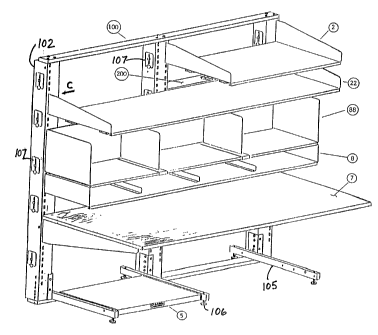
Fig. 1 is an isometric view from above, front and one
side of an exemplary system in accordance with the
invention, assembled to form a vertical equipment console;
10Fig. 2 is an isometric view from above, rear and the
other side of a similar system, with the racks and shelves
removed;
Fig. 3 is a detail section on the line A-A in Figure
2;
15Fig. 4 is a detail section on the line B-B in Fig. 2;
and
Fig. 5 is an exploded detail, from the same viewpoint
as Fig. 2, of the area indicated by the arrow C in Fig. 1.

20DESCRIPTION OF THE PREFERRED EMBODIMENT
Referring to the drawings, it will be understood that
the assemblies shown are exemplary only, and that the
modules of the system to be described may be assembled in
many different combinations to form vertical equipment
consoles to suit equipment to be housed. It should also be
understood that the configurations of the shelf and rack
units 2, 7, 8, 22 and 88 shown in the drawings of
themselves form no part of the invention: likewise the
tongue and slot connections (see Fig. 5) between these
parts and the vertical members 102 are conventional in
modular shelving systems, and may be replaced by any
alternative form of releasable connection means having
equivalent functionality. The only requirement of these
parts which is essential to the invention is that they can
be rehinged to provide adequate support, housing and access
for the equipment to be supported.

~3~9~

For the purposes of illustrations, the vertical
members 102 are shown connected top and bottom by cross
members 100, and supported by fore and aft extending legs
105 with feet 106 equipped with conventional levelling
screws. Alternative interconnect and support means could
be used, provided only that these are not such as to
prevent movement of the access doors 104 to be described
below, and provide adequate rigidity and support to the
structure as a whole.
Referring to Figs. 3, 4 and 5, the vertical members
102 are of rectangular cross-section, and may typically be
roll formed from coated strip seel of adequate gauge to
provide desired strength to the structure, with an opening
to the rear normally closed by a vertically extending
access door 104 connected to the member 2 by a vertical
hinge or hinges 111, the door normally being retained in a
closed position by a magnetic strip 113 attached to either
the upright or to the door as shown. Top and bottom walls
115 of he vertical members are secured to the cross-members
101 by bolts 109, while the legs 105 are secured to the
vertical members by brackets 116 and bolts 114. The bottom
walls 115 are cut away at 117 adjacent the door 104 to
provide clearance for cables to enter the interior top
vertical column. Attached at vertical intervals to the
front inside wall of the column are brackets 112 for the
attachment or suspension of power bars or other assemblies
providing electrical outlets. The side walls of the column
102 are each formed with a number of vertically spaced
apertures 118, large enough to pass plugs and cable
connectors of types typically used with computer or other
equipment to be supported by the assembly. Apertures about
2-5 cm. by 5 cm with rounded ends will usually be adequate.
These apertures are normally closed by removable closure
plates secured by thumbscrews 108 engaging threaded bores
119 in the column adjacent the aperture.

~ 737~

At appropriate locations, having regard to the
positioning of equipment on the assembly, additional cross-
members 200 of rectangular section is provided, also formed
with an opening to its rear normally closed by a door 201
connected by a hinge or hinges 211, this hinge horizontal
on this door also is normally retained closed by a magnetic
strip 213. The member 200 is secured to the vertical
members 102 by screws 115 engaging bores 119 after removal
of the associated plates 117.
An aperture or apertures 218 similar to the apertures
118 is formed in at least one of the upper and lower walls
of each cross=member 200, and closed when not in use by a
cover 107 secured by a thumbscrew.
In use, the system is assembled so as to provide a
support frame for shelves and racks such as the work
surface 7, the shelves 2 and 22, the paper tray 8, and the
book tray 88. The legs 105 may support a roll-out shelf 5.
Where shelves or work surfaces are to support electronic
equipment, cross members 200 are provided, secured as
described to the upright members 102.

The various shelves or racks are secured to the
support frame, in this example by engaging tabs on their
rear vertical edges in slots in the upright members 102,
using an arrangement well known in itself. Other
attachment systems may be substituted if desired within the
scope of the invention.
Opening the doors 104 and 201 exposes at the rear of
the frame a system of runways which may be used to route
power cords and connecting cables associated with equipment
placed on the shelves or racks. Power cords from equipment
may be routed through apertures 118 or 218 to reach the
equipment. It may be convenient to secure a power bar to
a bracket 112 within one or more of the uprights 102 into

~17~7~

which such cords may be plugged with the cable from such a
cord routed through the cutaway 117 to a convenient outlet.
Likewise network or telephone cables may be routed through
the cutaways 117 and up the uprights 102 to reach openings
118 or 218, while cables interconnecting equipment may also
be routed through the members 102 and 200 between openings
118 or 218. Once all required cables have been routed, the
doors may be closed.

In the embodiment shown, the legs 105 project somewhat
to the rear of the frame, thus ensuring that sufficient
space will be left between the upright frame and an
adjacent wall to permit access to the doors 104 and 201 if
it is necessary to add, remove or reroute cables.


Representative Drawing
A single figure which represents the drawing illustrating the invention.
Administrative Status

For a clearer understanding of the status of the application/patent presented on this page, the site Disclaimer , as well as the definitions for Patent , Administrative Status , Maintenance Fee  and Payment History  should be consulted.

Administrative Status

Title Date
Forecasted Issue Date 2001-12-25
(22) Filed 1996-04-10
(41) Open to Public Inspection 1997-10-11
Examination Requested 1998-10-20
(45) Issued 2001-12-25
Deemed Expired 2008-04-10

Abandonment History

There is no abandonment history.

Payment History

Fee Type Anniversary Year Due Date Amount Paid Paid Date
Application Fee $0.00 1996-04-10
Maintenance Fee - Application - New Act 2 1998-04-14 $100.00 1998-04-09
Request for Examination $400.00 1998-10-20
Maintenance Fee - Application - New Act 3 1999-04-12 $100.00 1999-04-12
Maintenance Fee - Application - New Act 4 2000-04-10 $100.00 2000-04-10
Maintenance Fee - Application - New Act 5 2001-04-10 $150.00 2001-03-05
Final Fee $300.00 2001-10-01
Maintenance Fee - Patent - New Act 6 2002-04-10 $150.00 2002-01-14
Maintenance Fee - Patent - New Act 7 2003-04-10 $150.00 2003-04-10
Maintenance Fee - Patent - New Act 8 2004-04-13 $200.00 2004-06-30
Expired 2019 - Late payment fee under ss.3.1(1) 2004-11-02 $50.00 2004-06-30
Maintenance Fee - Patent - New Act 9 2005-04-11 $400.00 2006-04-10
Maintenance Fee - Patent - New Act 10 2006-04-10 $250.00 2006-04-10
Owners on Record

Note: Records showing the ownership history in alphabetical order.

Current Owners on Record
HULL, LESLIE
Past Owners on Record
None
Past Owners that do not appear in the "Owners on Record" listing will appear in other documentation within the application.
Documents

To view selected files, please enter reCAPTCHA code :


To view images, click a link in the Document Description column. To download the documents, select one or more checkboxes in the first column and then click the "Download Selected in PDF format (Zip Archive)" or the "Download Selected as Single PDF" button.

List of published and non-published patent-specific documents on the CPD .

If you have any difficulty accessing content, you can call the Client Service Centre at 1-866-997-1936 or send them an e-mail at CIPO Client Service Centre.


Document
Description 
Date
(yyyy-mm-dd) 
Number of pages   Size of Image (KB) 
Representative Drawing 1997-11-07 1 15
Representative Drawing 2001-11-27 1 21
Cover Page 2000-12-11 2 75
Cover Page 1996-07-16 1 14
Abstract 1996-07-16 1 27
Description 1996-07-16 5 203
Claims 1996-07-16 1 37
Drawings 1996-07-16 4 109
Representative Drawing 2000-12-11 1 15
Cover Page 2001-11-27 2 55
Claims 1998-12-29 1 48
Cover Page 1997-11-07 2 75
Correspondence 2004-09-13 1 13
Fees 2002-01-14 1 31
Fees 2003-04-10 1 30
Correspondence 2001-10-01 1 44
Fees 1998-04-09 1 37
Assignment 1996-04-10 4 141
Prosecution-Amendment 1998-10-20 12 388
Fees 2001-03-05 1 31
Fees 1999-04-12 1 29
Fees 2000-04-10 1 31
Fees 2004-04-13 1 33
Fees 2004-06-30 2 65
Fees 2004-06-30 2 63
Fees 2006-04-10 1 29
Fees 2006-04-10 1 27