Note: Descriptions are shown in the official language in which they were submitted.
21 73833
'
Outer wall element for buildings, in particular wainscot panel
for the breastwork area of the wall of a buildinq
The object of the invention is an outer wall element for
buildings, in particular breastwork or wainscot panels in the
breastwork area of a building wall, in accordance with
Claim 1.
Façade claddings, which are used in the passive use of
solar energy on the opaque parts of the building envelope, are
known from W0-82/03 100 as the latest state of the art. In
this source, using Fig. 1, an outer wall construction is
described in which, between a transparent outer shell and the
solid wall, a transparent outer heat insulating layer is
provided adjacent to the outer shell and an insulating layer
on the outer side of the wall. The latter is separated from
the transparent outer heat insulating layer by a solar
radiation absorbing layer. The heat created in the latter is
conducted away by the insulating layer in the wall. In order
to avoid overheating the absorbing layer and the insulating
layer, the insulating layer consists of a material whose
thermal conductivity can be changed considerably as a function
of the temperature. For that purpose, the material contains a
normally liquid heat transfer medium, which evaporates on the
warm side of the insulating layer. The vapour is diffused
through the pores of the material to the cold side of the
layer and there releases its heat and condenses on the wall.
The condensate penetrates, for example by capillary action,
back to the warm side of the layer thus creating a cycle in
the heat transfer medium between the liquid to the vaporized
state and transporting the heat principally from the outside
to the inside. As the heat conductivity increases very
rapidly and strongly with increasing solar radiation with a
rise in temperature, a disproportionately greater quantity of
heat is conducted through the insulation layer into the solid
wall, so that the actual increase in the temperature of the
absorbing layer is correspondingly lower, while the wall on
the inside of the building may be warmer than is desired. In
1 2t~8~3
addition, an exterior cladding of similar design is known from
EP-A-O 362 242. Here, in order to prevent the penetration of
solar radiation into the interior of the outer wall structure
from causing overheating that will damage materials, the inner
heat insulating layer is designed to be somewhat translucent
with a transmittance of less than 10% and a coefficient of
absorption exceeding 15%, so that the absorption of the
penetrating solar radiation within the heat insulating layer
occurs over a relatively thick layer area. The heat
insulating layer must be so thick overall that, when there is
usable solar radiation, a temperature profile is created in
the heat insulating layer whose maximum value inside the
insulating layer is located between the inner and outer
boundary surfaces of the layer. This can, particularly in the
case of expected strong insolation, require a great thickness
of the inner insulating layer and result in a construction
thickness of the outer wall which is greater than that set by
structural engineering requirements.
From CH-A-678 203, an outer wall design is known, in
which an outer wall is insulated by an outer transparent
insulating layer and protected by a superimposed weather
protection sheet of transparent material. The outer wall has a
solar absorbing dark cladding on the surface adjacent to the
outer heat insulating layer. An inner heat insulating layer
between this layer and the outer wall is not provided.
Excessive heat in the wall construction is avoided by the
weather protection sheet, which owing to the manner in which
it is mounted, allows more of the low winter sun to pass
through than of the high summer sun. To that end, the surface
of the weather protection sheet is arranged in relief fashion
with two parts, oriented in opposed directions, one of which
is transparent and the other is covered with an opaque paint
layer, which results in a shading that varies with the
incoming angle of the sunlight. A smooth outer glazing surface
is not possible with this kind of weather protection sheeting.
From the literature, in an article entitled
"Thermochromic Gels for Control of Insulation" in the magazine
2 1 73833
Solar Energy, Volume 50, number 5, May 1993, pages 407 - 414,
an outer wall design is known in which the solid outer wall
also has a solar absorbing dark cladding on the surface
adjacent to the outer heat insulating layer, and there is also
no inner heat insulating layer provided between this layer and
the outer wall. The outer shell, which is separated from the
absorbing layer by a transparent outer heat insulating layer,
has thermochromic layers which affect the radiation
transmission depending on the temperature, so that when a
characteristic temperature is exceeded, the radiation
transmission is actually reduced. Such layers are achieved by
including a thermochromic gel in the narrow space between two
glass panes. Such an outer shell design is actually more
construction-intensive as a shell designed using traditional
glazing.
A similar outer wall design as in W0-82/03 ioo is known
from EP-A-0 473 859. Although the insulating layer in this
instance does not have any changing thermal conductivity,
there is, however, a space provided between the absorbing
layer and the insulating layer in which there is a liquid heat
transfer medium that circulates between the space and a piping
system contained within the solid wall and thus transports the
heat from the absorbing layer by convection directly into the
solid wall.
The purpose of the invention is to design an outer wall
structure in such a way that, under conditions of highest
possible utilization of solar energy and assured comfort in
the interior space, excessive temperatures that would damage
materials will be avoided. The depth of the wall component is
to be as narrow as possible and in particular not greater than
the structural requirements for the load-bearing structure,
especially, for example, the columns and beams.
In the outer wall structure in accordance with the
invention, the absorption of incoming solar radiation is
essentially in the absorbing layer delimiting the transparent
outer heat insulating layer located adjacent to the inner heat
insulating layer, on which thus generally the highest possible
- 2 1 738~3
temperatures within the wall components occur. This layer can
be very thin when it is impermeably only to solar radiation.
Although, the reduced g-value of the outer shell desired in
accordance with the invention has a reduced absorption of
solar energy in the outer wall element, it does however,
ensure that with the highest possible insolation a maximum
temperature in the absorbing layer is not exceeded, so that
destruction of material by overheating cannot occur. The
inner shell, that is, the inner heat insulating layer and the
end layer, then need only be designed relative to their heat
transfer resistance in such a way that at an allowable maximum
temperature at the absorbing layer, the temperature occurring
at the interior space side of the inner shell and that at the
interior wall side of the interior air, are within temperature
ranges determined by the thermal conductivity resistance, and
are perceived by persons within the interior area as
comfortable. This can be achieved through a comparatively thin
thickness of the inner heat insulating layer. Higher values of
the heat transfer resistance of the inner heat insulating
layer are generally disregarded in the framework of this
invention and would only unnecessarily increase the size of
the inner heat insulating layer and/or the end layer and,
consequently, also increase the design depth and the
construction efforts and financial expenditures of the outer
wall element in accordance with the invention overall.
The reduced absorption of solar radiation resulting from
the desired reduction of the g-value of the outer shell
through application of the invention, is used optimally by
adapting the heat transfer coefficient k of this shell, when
the correspondingly reduced k-value limits the outward heat
loss of the absorbing layer and the outer shell. It is ,
therefore, desirable that the single pane glazing forming the
outer shell, consists of an inner heat absorbing layer,
particularly an L-E layer, and/or à solar screen layer.
Another very advantageous embodiment is one characterized by
having the glazing consist of insulating glass elements of
each two or three glass panes. In the latter case, the
2~ 73833
elements could have reduced spaces between the panes, in order
to keep the expansion effect (pumping effect) of the air in
the intervening spaces small when the air heats up. It is
also recommended that the glass panes in the insulating glass
components should be provided on individual, several or all
sides (below they are also termed positions) with heat
absorbing layers, in particular with L-E layers. In addition,
it is useful to provide the insulating glass components or
their glass panes with sun screen layers. Such sun screen
layers should be optimized in such a way that the solar
energy, in accordance with the invention, is used as much as
possible without excessive temperatures occurring at the
absorbing layer. Furthermore, the spaces between the panes of
the insulating glass components can be filled with an inert
gas, in order to serve to adjust the heat transfer -
coefficients to the existing conditions and requirements, for
example, lower g-values for south orientations of the outer
wall structure, medium g-values for east/west orientations and
high g-values for north orientations.
The outer shell can, however, also be composed of a
specific design suitable for special systems, where these
generally consist of two transparent glass panes and a
prismatic or honeycomb structure in the intervening space
approximately perpendicular to the plane of the panes.
A particularly advantageous embodiment of the invention
is characterized by the fact that a heat retaining layer is
located on the side of the interior shell inner facing the
transparent inner heat insulating layer.
The heat retaining layer has the advantage that, when the
outer wall structure is in accordance with the invention, the
solar energy received in the absorbing separation layer in
front of it is stored partially in the solid storage mass of
the heat retaining layer and is released again if the supply
of solar energy has in the meantime diminished or should no
longer continue to exist. Depending on the thermal capacity
and heat insulating capacity of the storage and insulating
materials forming the layers in the inner shell, the
2 1 73833
utilization of the solar energy supply can, depending on the
thermal properties of the other parts of the wall structure,
in particular the outer shell and the transparent outer heat
insulating layer, be enhanced, notably with respect to the
prevention of overheating in the wall component and delaying
the release of the stored heat in relation to the actual solar
energy radiation. For with other conditions remaining the
same, the heat retaining layer creates a lower temperature on
the absorbing layer, within the outer wall component in any
case and on its inner wall surface, and this can be used to
raise the g-value of the outer shell in order to use up the
solar energy supply more completely without exceeding the
permissible maximum temperatures. Moreover, the heat retaining
layer should have the optimum heat capacity possible, in order
to be able to absorb the solar energy supply as fully as
possible, without any unnecessarily great temperature
variances occurring. Particularly useful embodiments are
characterized in that the heat retaining layer contains
retaining materials of one or more mineral sheets, ceramic
sheets, glass, natural or synthetic materials, particularly
including gravel-based concrete. Storage materials which work
as latent heat retainers can also be used, such as for example
sodium sulfate. However, the retaining material of the
retaining layer can also consist of synthetic material,
particularly of one or more synthetic sheets, because
synthetics possess as a rule about double the specific heat of
concrete. This reduced density of the synthetic material as
compared to the heavier retaining materials balances out, so
that approximately equal storage capacities can be obtained
with concrete and with synthetic material as the retaining
mass, for example. The retaining materials mentioned above
can, in accordance with the invention, be used either
individually or mixed in combination with each other in the
heat retaining layer.~
Further, it is recommended that storage materials of low
thermal conductivity are selected for the heat retaining
layer, so that the heat stored in it does not get given off to
2 1 73833
~,
quickly to the surrounding environment, even when there are
heat insulating layers, when the temperature drops on both
sides of the wall element. The heat retaining layer should,
therefore, cool only slowly. For that reason, the inner heat
insulating layer is arranged between the heat retaining layer
and the end layer of the inner shell.
The inner heat insulating layer can in its simplest form,
be made up of an air layer. Generally, however, the inner heat
insulating layer contains certain insulating materials , such
as PUR [polyurethane] foam, PS ~polystyrene] foam, glass
fibres, mineral fibres, or similar materials. There is also
the option of designing the inner heat insulating layer using
multiple layers with air layers between 5 and 50 mm,
preferably 20 mm. Greater thicknesses for these air layers
should be avoided, so that heat convection through air
circulating within this layer remains low and the heat
insulation achieved by this air layer does not unnecessarily
reduced. It may contain an end sheet of metal, particularly
aluminum or steel. This end layer may also contain a retaining
material, in particular concrete, which can be achieved in an
especially simple manner by having the retaining material
consist of the concrete breastwork of the building wall.
As regards the construction of the outer transparent heat
insulating layer adjacent to the inner shell, there are
several options in accordance with the invention. For example,
this transparent heat insulating layer in its simplest form
can again be an air layer between 5 and 50 mm, preferably 20
mm. The air layer can be located immediately next to the
absorbing layer. Between the air layer and the absorbing
layer, however, there can be a glass pane. However, the
transparent outer heat insulating layer can also be composed
of capillary sheets of transparent plastics with a honeycomb
or chamber structure perpendicular to the layer, as is known
from Bauphysik 13 (1991), H. 6, pages 217 - 224 entitled
"Transparante Warme~7mm~7ng, Materialien, Systemtechnik und
Anwendung" [Transparent heat insulation, materials, systems
technology and application], and which requires no further
2173833
discussion here for that reason. Furthermore, the outer
transparent heat insulation layer can also consist of fibre
glass and/or acrylic resin foam, either individually or in
combination as the insulating material.
The absorbing layer, together with the deliberately
reduced g-value of the outer wall element can aid in
optimizing the external appearance of the latter, wherein lies
another important advantage of the invention. That is because
the small g-values considerably reduce the view through the
outer shell, thereby making it more difficult to see through
the outer wall elements behind the outer shell as well, thus
making it easier to meet the aesthetic requirements of the
appearance.
In the case of an outer wall element with a heat
retaining layer adjacent to the absorbing layer, then a
suitable embodiment of the glazing could be single clear glass
panes or insulating glass elements consisting of two clear
glass panes.
Examples are given below of embodiments of the invention
which are explained by means of the drawings; the following
are shown:
Fig. 1 section through the layer structure of a wainscot
panel in accordance with the invention, shown
schematically,
5 Fig. 2 another embodiment of the wainscot panel shown as in
Fig. 1,
Fig. 3 schematic diagram showing the layer structure of the
outer shell only.
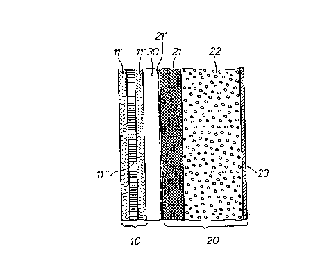
In the drawing the outer shell receiving solar radiation
is generally labelled 10 and the inner shell is generally
labelled 20. Between the two shells there is a transparent
outer heat insulation layer 30 immediately adjacent to the
outer shell 10, while the inner shell 20 consists of multiple
2 1 73833
layers with a heat retaining layer 21 and an inner heat
insulating layer 22, whereby the heat retaining layer 21 is
positioned on the side of the inner shell 20 facing the
transparent heat insulating layer 30. The retaining material
5 of this heat retaining layer 21 may take various forms, for
example, mineral sheets, ceramic sheets, glass or natural or
artificial stone, in the latter case especially concrete, but
may also be made of synthetic, especially one or more plastic
sheets which, however, is not shown in detail in the drawing.
This inner shell 20 has an end layer 23 delimiting the outer
wall element on the inner side, and its side facing the outer
shell 10 a heat insulating layer 22 is provided which is
located between the heat retaining layer 21 and the end layer
23. The heat insulating layer 22 may contain PUR
15 [polyurethane] foam or PS [polystyrene] foam, glass fibres,
mineral fibres etc. as insulating materials. The heat
insulating layer 22 may also contain one or more layers of air
10 to 50 mm, preferably 20 mm, thick. This is also not shown
in detail in the drawing. End layer 23 itself should in any
20 case be vapour-proof and may consist of an end sheet of metal,
such as aluminum or steel, but may also consist of solid
storage material, in particular concrete.
The transparent heat insulating layer 30 can again be an
air layer between 5 and 50 mm thick, preferably 20 mm.
25 However, the transparent outer heat insulating layer 30 can
also be composed of capillary sheets of transparent plastics
with a honeycomb or chamber structure perpendicular to the
layer, which also is not illustrated in the drawings for
reasons of simplicity. Furthermore, the outer transparent heat
30 insulation layer 30 can also consist of fibre glass and/or
acrylic resin foam, either individually or in combination as
the insulating material. The heat retaining layer 21 is
- - positioned on the side of the inner shell 20 facing the
transparent heat insulating layer 30, and is provided with a
35 . radiation absorbing, spectrally selective absorbent, if
required, radiation-impermeable layer 21', which may be
designed as a thin coating.
2 1 73833
The outer shell 10 consists of glazing which may be
provided with one or more sun screen coatings for the purpose
of lowering the g-value. In the case of an outer shell 10 with
a heat retaining layer 21 adjacent to the heat insulating
layer 30, the glazing can consist either of individual clear
glass panes or insulating glass components made of two or more
clear glass panes. In general, the glazing is formed by
individual glass panes 11, if necessary provided with an inner
heat absorbing layer, in particular an L-E coating and/or sun
screen coatings, which results in a lower k-value.
Furthermore, the glazing can consist of insulating glass
elements made up of two or three glass panes 11, 12, 13, in
which case the insulating glass elements may have spaces
between the panes which are reduced. The glass panes 11, 12,
13 may also have heat absorbing coatings, in particular L-E
layers, on one, several or all sides of the panes in addition
to the sun screen coatings, where the L-E layers on the open
surfaces of the panes may be formed by pyrolytically applied
layers of stannic oxide. In addition, there is the option that
the insulating glass elements, or their glass panes 11, 12,
13, are provided with sun screen layers. The spaces between
the panes can also be filled with an inert gas. In
consequence, it is recommended in accordance with the
invention that in practice, with a view to optimizing each
adjustment of the k-value and the g-value to the existing
requirements, that is, with respect to the maximum temperature
occurring on the absorbing layer 21' the following
combinations, explained in detail in Fig. 3, can be described
as particularly useful:
1. Single glass pane with a heat absorbing and sun screen
pane 11 with the sun screen layer in position 1 for a
deliberately reduced g-value and an L-E layer in position
2,
2. Double insulating glazing consisting of two glass panes
11, 12 with a sun screen layer, for example,
2 1 73833
11
sun screen layer in position 2,
heat absorbing layer (L-E) in position 3,
or
sun screen layer in position 2,
heat absorbing layer (L-E) in positions 3 and 4,
with the heat absorbing layer in position 4
consisting of a pyrolytically applied layer of
stannic oxide,
or
sun screen layer plus heat absorbing layer in
position 2, heat absorbing layer (K) in position 4,
in each case with or without inert gas filling the spaces
between the panes.
3. Triple insulation glazing made of glass panes 11, 12, 13
with
sun screen layer in position 2,
heat absorbing layer in position 3,
heat absorbing layer in position 5,
or
sun screen layer in position 2,
heat absorbing layer in position 3,
heat absorbing layer in position 5,
heat absorbing layer in position 6,
or
sun screen and heat absorbing layer in position 2,
heat absorbing layer in position 5,
21 73833
or
sun screen and heat absorbing layer in position 2,
heat absorbing layer in position 5,
heat absorbing layer in position 6,
in each case with or without inert gas filling the spaces
between the panes.
The outer shell 10 may also, in accordance with the
embodiment in Fig. 2, consist of two transparent glass panes
11' and of a prismatic or honeycomb structure 11" in the
intervening space approximately perpendicular to the plane of
the panes.