Note: Descriptions are shown in the official language in which they were submitted.
2174054
95B11 3/PG -1-
MACHINING OF MATERIALS
The present invention relates to apparatus for and methods of removing material
from a workpiece and in particular to apparatus for and methods of machining a
blind slot in a workpiece.
The expression "blind slot" used throughout this specification is intended to embrace
a groove, slit, slot or hole which does not extend completely but only partiallythrough a workpiece.
It is known to machine a groove in a metal workpiece by vertically impinging a laser
beam on the surface of the workpiece to melt a volume of the metal which is
subsequently removed by an off-axis jet of nitrogen gas. A narrow groove is formed
by moving the workpiece relative to the stationary nitrogen gas nozzle and laserbeam.
This process tends to suffer from low efficiencies because the speed of the gas jet
and therefore the lift of the molten material from the groove is reduced due to
pressure build-up at the base of the groove. This results in the production of
relatively shallow grooves.
It is also known in a laser caving process to utilise a laser and a gas jet which both
impinge on the surface of the material at an angle of 4045.
In International Patent Publication NumberW094/21419, there is disclosed a
method of machining a through slot in a workpiece which comprises heating the
surface of the workpiece with a laser beam and directing towards said surface two
gas streams.
The production of melt volumes utilising a high power laser is a relatively easy task
providing that the l"aterial of the workpiece absorbs the radiation efficiently. The
2174~54
95B1 1 3/PG -2-
problem with laser machining is not melt production but the removal of the melt with
suffficient speed and effficiency. This is particularly relevant when machining very
narrow, deep blind slots in a workpiece.
It is an aim of the present invention to provide an apparatus for and a method of
machining a workpiece using a heat source, for example, a laser beam in which the
molten metal is removed, particularly from deep blind grooves or slots more
effectively than in known processes.
According to one aspect of the present invention a method of machining a blind slot
in a workpiece comprises the steps of heating the surface of the workpiece above its
melting temperature and directing at least two gas streams such that together with
the base of the slot they create a vortex with a predetermined rotational direction for
removing the molten material from the slot.
Preferably, the surface of the workpiece is heated with a beam of laser energy and
the first gas stream is applied as a jet to the workpiece at substantially right-angles
to the surface, whilst the second stream is applied as a jet to the workpiece at an
acute angle to the surface.
Alternatively, the first gas stream is created by a relative vacuum applied to the
surface of the workpiece immediately adjacent the beam of laser energy and the
second stream is applied as a jet to the workpiece at an acute angle to the surface.
According to a further aspect of the present invention, an apparatus for machining a
blind slot in a work~uiece comprises a source of heat for melting the surface of the
workpiece and means for producing at least two gas streams which interact with the
base of the slot in such a manner that they create a vortex with a predeterminedrotational direction for removing the molten material from the slot.
2174054
95B11 3/PG -3-
An embodiment of the invention will now be described by way of example, reference
being made to the Figures of the accompanying diagrammatic drawings in which:-
Figure 1 is a schematic diagram of an apparatus for machining a blind slot in aworkpiece;
Figure 2 is a schematic diagram similar to Figure 1 but illustrating the velocity
vectors of two gas jets;
Figure 3 is a graph illustrating the gas velocity from the bottom of a slot being
machined in the workpiece of Figure 1, as a function of the velocity of a gas jet; and
Figure 4 is a graph of slot depth and surface debris against gas pressure; and
Figure 5 is a perspective view of a workpiece machined with a plurality of blind slots
according to the method of the present invention.
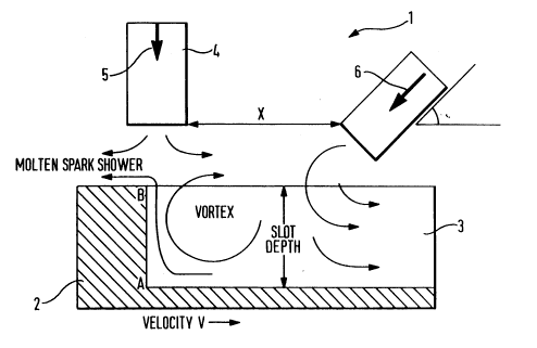
As shown in Figures 1 and 2, an apparatus 1 for machining a deep blind spot 3 in a
workpiece 2 includes a source 4 of laser energy eg. a CO2 laser which is capable of
directing a beam of laser energy at substantially right-angles to the upper (as shown)
surface of the workpiece 2. A nozle assembly 8 is provided for directing a first jet 5
of gas, for example oxygen, on to the upper surface of a workpiece 2 substantially
co-axially with the beam of laser energy. Spaced from said jet 5 is a second jet 6 of
gas, for example nitrogen, which is also directly towards the upper surface of the
workpiece 2 at an acute angle alpha (a) to said surface in the general direction of
the first gas jet. The distance 'x' between the jets 5,6 can be between 2 and 6 mm.
In use, the workpiece 2 is c~used to move to the right as shown, relative to the CO2
laser beam which is focused on to the surface of the workpiece with sufficient power
to melt a small volume of the workpiece 2 thereby creating a slot 3. Substantially
simultaneously the first and second gas jets 5,6 create together with the base of the
2174~S4
95B1 1 3/PG -4-
slot 3 a vortex with a predetermined rotational direction which removes the molten
material and other debris from the slot 3.
The vortex rotational velocity is controlled by varying the velocity of the first jet of gas
which is effectively a stabilising jet. Referring to Figure 3, this illustrates the uplifting
gas velocity from the bottom of the slot 3 to the surface of the workpiece at a
location close to the slot front marked A-B in Figure 1, as a function of the velocity of
the first stabilising jet 5. If the velocity is very low, for example 5 metres per second,
the action of the second jet 6 serves to blow the molten material and debris out of
the slot 3.
As a generality by increasing the stabilising jet velocity, the uplifting gas velocity
increases. For example, increasing the stabilising jet velocity to 100 metres per
second the uplifting gas velocity increases to a maximum of 130 metres per second.
However, further increases in the stabilising jet velocity to 150 to 200 metres per
second serves to reverse the effect and the uplifting gas velocity reduces as the
vortex is on the verge of reversing its direction.
It is believed that the vortex effectively sucks any molten metal out of the depth of
the slot 3. By varying the speed of the workpiece beneath the laser beam and thestabilising gas jet 5, the depth of the slot 3 can be conl~olled. Further, the distance
between the sources of the gas jets 5, 6 indicated by X in Figure 1, is influential in
controlling the depth of the slot 3. The greater the value of X the greater the depth.
By using oxygen as the first gas jet i.e. the stabilising jet, the exothermic energy
liberated in the slot allows for substantially deeper slots than with other gases.
Slots have been produced with a variation in the pressure and ther~fore velocity of
the first stabilising jet. In the above described embodiment, the sl~bilisi"g jet was
composed of pure oxygen with the second side jet of nitrogen set at a fixed pressure
of 11 bar.
- 2174~5~
95B11 3/PG -5-
Figure 4 gives a plot of slot depth and surface debris against oxygen pressure. Too
low an oxygen pressure produces ineffective removal and the slot depth decreaseswith surface debris increasing. Below a pressure of 1.5 bar the process was
unstable. The optimum pressure for a particular nozzle configuration was found to
be 2.5 bar. Too high a pressure produces reversal of the uplift and the slot closes
producing a catastrophic oxygen reaction.
Figure 5 illustrates a workpiece formed with a plurality of blind slots for example,
cooling channels. The workpiece is a 20mm thick steel block and the slots where
machined at a rate of 1 .5m/min using a 1 KW C02 laser. The slots are 300~ m wide
and 3mm deep with a spacing of 1 mm between each slot. The nitrogen jet was
applied at a pressure of 11 bar and the oxygen jet at a pressure of 2.4 bar.
Although reference has been made in the above described embodiment to a first jet
of gas directed towards the workpiece it has been found that a vortex can be
cred~ecJ equally well by reversing the direction of the first jet by creating a vacuum.
Furthermore, although in the above described embodiment only two gas streams
have been described, it will be clear that more than two gas streams can be utilised
to create the vortex.