Note: Descriptions are shown in the official language in which they were submitted.
2174186
This invention relates generally to a
precompression pump sprayer of the type wherein a plunger
rod having a discharge passage and an enlarged discharge
valve seat at its lower end extends through a reciprocable
piston located in the pump cylinder for sliding movement
between an inactive position and an end-of-stroke position.
The piston engages the valve seat in a discharge closed
position and moves out of enegagement with the valve seat in
a discharge open position. A primary spring biases the
plunger rod toward its inactive position, and a secondary
spring extends between the piston and a projection on the
plunger rod for transmitting movement of the plunger rod to
the piston, the secondary spring having a predetermined
spring force for biasing the piston toward the discharge
closed position. During pump actuation, the discharge
passage opens when the pump chamber pressure exceeds the
force of the secondary spring.
More particularly, the present invention relates
to an improvement over prior art structures of this general
type by the provision of a quick acting discharge valve
which avoids frictional engagement between the valve seat on
the plunger rod and the piston which acts as a valve, to
thereby effect more precise precompression values which
avoids the dispensing of fluids at low pressures thereby
avoiding dribbles, drips and drooling of product out of the
discharge orifice.
2174186
Precompression pump sprayers of the general type
characterized above enjoy widespread use for the fine mist
spraying of liquids such as perfumes and colognes as well as
many other personal care products. One of the features of
the pump is to have a relatively short overall dimension,
comparable in size to that of a perfume package having no
pump sprayer, i.e., it is desirable for the pump sprayer to
have the same cover, overcap, etc. and at the same time have
its pump mechanism not visible through the glass or plastic
bottle at its neck, similar to that of a package without a
pump. To achieve this objective, and because the inner
diameter of the typical bottle neck for such a package is of
limited size, it is important to achieve maximum
optimization of the height dimension of each element of the
pump sprayer.
One of the many drawbacks associated with the use
of nonprecompression pump sprayers is its inability to
quickly shut off the discharge at the end of the pressure
stroke, thereby causing residual product to be discharged in
dribbles and drips.
U.S. Patent 4,051,983 is a precompression pump
sprayer having a single piston return spring, and a conical
discharge valve seated within the piston with the result
that a highly acceptable fine mist spray is discharged
without producing dribbles and drips or drooling on
discharge shutoff.
21741~6
However, the degree of precompression cannot be
separately adjusted, and the precompression force varies
during piston travel so that the finger force required for
actuation is high. Moreover, the output of the pump in
relation to the length of the stroke is low, and the pump
dimensions are large in relation to the output.
U.S. Patent 4,856,677 discloses a precompression
pump sprayer with two springs. The overall height of the
pump is low, and the full stroke is converted in output.
Reduced finger force is required for pump actuation, and the
two springs act in opposed relation rendering the
precompression force reasonably constant during piston
travel.
However, an annular seal at the lower end of the
piston requires a relative sliding of the plunger rod to
cover and uncover a lateral discharge port for controlling
the discharge. Such an arrangement gives rise to the
production of dribbles and drips and even drooling at the
beginning of each pressure stroke.
U.S. Patent 4,941,595, commonly owned herewith,
discloses a precompression pump sprayer having a secondary
cylinder affixed to the pump piston for housing a secondary
piston/discharge valve mounted for sliding movement, and a
secondary spring urging the secondary piston toward a
discharge valve closing position.
This pump sprayer requires a low force to actuate
due to the constant precompression during the stroke. A
2 i 7 4 1 8~
highly satisfactory fine mist spray is effected without
producing dribbles and drips or drooling as abrupt and clean
discharge shut off is effected by the provision of the
conical discharge valve.
A wide range of products can be effectively
sprayer by the known sprayer adapting the characteristics of
the liquid to be sprayed by changing the secondary spring.
Viscous products and gels can therefore be effectively
sprayed.
However, a relatively large pump cylinder is
required to accommodate the secondary cylinder.
U.S. Patent 5,234,135 is similarly structured to
that of the U.S. Patent 4,856,677 in that frictional
relative sliding movement is required between the plunger
rod and the piston for covering and uncovering lateral
discharge ports to control the discharge. Two springs are
utilized independently, and a suck-back feature is added.
The pump requires a low force to actuate and has
relatively short overall dimensions. The suck-back system
at the end of the plunger stroke introduces a vacuum in a
second inner chamber for avoiding the formation of dribbles
and drips at the discharge orifice.
However, the frictional sliding movement
necessitated between the plunger rod and the piston for
controlling the discharge impedes a rapid and complete
shutoff of the discharge giving rise to the production of
dribbles, drips drooling or even a reduced quality in spray.
-- 5
2 1 74 1 86
Although such prior art sprayer couId be adapted to
different products, in practice the range is reduced because
of the low quality spray (i.e., jet) production.
It is therefore an object of the present invention
to provide a precompression pump sprayer having dual springs
which enhance the precompression values while avoiding the
disadvantages of the known prior art pump sprayers by the
provision of a quick acting and clean discharge shut off
without the need for a suck-back feature, and having
relatively short overall dimensions. The present pump
requires a low force to actuate and produces a high quality
fine mist spray without the production of dribbles and drips
or drooling at the beginning or end of the pressure stroke.
A conical (or spherical or parabaloid-shaped)
discharge valve seat, and a discharge valve on the piston
having a sharp circular edge bearing against the conical
valve seat along a circular line without sliding,
effectively control the discharge without leakage through
its orifice at the beginning or end of its pressure strokes.
A wide range of products can be effectively sprayed as the
pump can be adapted to its characteristics by changing the
secondary spring. Because of the improved spray, less
product remains at or near the discharge orifice, thereby
avoiding the need for a suck-back feature.
Other objects, advantages and novel features of
the invention will become apparent from the following
detailed description of the invention when taken in
2 1 74 1 86
conjunction with the accompanying drawings.
Having thus generally described the invention,
reference will be made to the accompanying drawings
illustrating an embodiment thereof, in which:
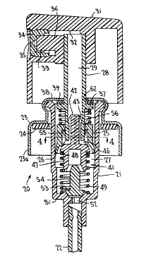
Figure 1 is a vertical sectional view of one
embodiment of the precompression pump sprayer according to
the invention shown in its inactive position;
Figure lA is a vertical sectional view of an
alternate discharge valve seat for carrying out the
invention;
Figure 2 is a view similar to Figure 1 of the pump
sprayer at the plunger end-of-stroke position to facilitate
priming;
Figure 3 is a view similar to Figure 1 of the pump
sprayer at the plunger end-of-stroke position during pumping
operation;
Figure 4 is a sectional view taken substantially
along the line 4-4 of Figure 1;
Figure 5 is a vertical sectional view of part of a
precompression pump sprayer according to another embodiment
of the invention; and
Figures 6, 7, 8, 9 and 10 are vertical sectional
views of relevant portions of the precompression pump
sprayer according to other embodiments of the invention.
Turning now to the drawings wherein like reference
characters refer to like and corresponding parts throughout
the several views, one embodiment of the pump sprayer of the
2174186
invention, generally designated 20 in Figures 1 to 3,
comprises a pump body which includes a pump cylinder 21
supporting a dip tube 22 extending into a container (not
shown) of product to be sprayed. The pump body is mounted
on the container neck (not shown) by the provision of a
closure which may be in the form of a ferrule 23 crimped or
otherwise snapped onto the upper end of the pump cylinder.
Skirt 23a of the ferrule is likewise crimped over a head on
the container neck for retaining the closure on the
container. An annular gasket 24 is interposed between the
shoulder of the cap and the upper rim of the container neck
for sealing against leakage. Of course, other closures such
as a threaded closure can be provided in lieu of a ferrule
without departing from the invention.
A pump piston 25 is mounted within the cylinder
for reciprocation, the cylindrical body portion of the
piston having a depending, outwardly flaring flange or lip
seal 26 in sliding sealing engagement with the inner wall of
the pump cylinder and therewith defining a variable volume
pump chamber 27.
A pump actuator or plunger includes a plunger rod
28 which may be hollow to form a discharge passage 29, or
may otherwise have a channel or channels forming the
discharge passage. The plunger rod extends through the
piston for reciprocation between an inactive position shown
in Figure 1 and end-of-stroke positions shown in Figure 2
(during priming) and shown in Figure 3 (during pumping). An
2174186
upper end of the plunger rod extends outwardly of the upper
end of the pump cylinder and has mounted thereon a plunger
cap 31 of known construction as having a discharge channel
32 communicating with the discharge passage channels 33 of
the discharge orifice cup 34 having a discharge orifice 35
containing spin mechanics and mounted on a discharge probe
36 for pulverizing the liquid during pumping to effect a
fine mist spray.
The plunger rod has a laterally extending annular
flange 37 underlying an upper wall 38 of the closure, an
annular gasket seal 39 being interposed between wall 38 and
flange 37 and being secured to the latter.
An enlarged plug element 41 is plugged into the
lower end of the plunger rod, the plug having an upstanding
probe 42 containing discharge channels 43 and an outer ledge
44 (see Figure 6) which snap fits together with an inner
ledge 45 formed on rod 28.
Element 41 has laterally extending discharge ports
46, and a depending sleeve or hollow extension 47 projecting
from a shoulder 48 into the pump chamber.
A primary spring, which may be in the form of a
coil spring 49, extends between bottom wall 51 of the pump
cylinder and shoulder 48 for spring biasing the plunger
toward its inactive position of Figure 1.
Bottom wall 51 of the cylinder has an inlet port
52 and an inlet valve seat 53 against which a shuttle valve
54 is seated for controlling the inlet. The shuttle valve
2174186
-
is guided within sleeve 47 during the plunger downstroke
positions of Figure 2 and 3, and during the plunger return.
The piston has a downwardly flaring inner lip seal
55 at its upper end in sliding sealing engagement with the
outer surface of the plunger rod. The lower inner end of
the body portion of the piston is urged into tight sealing
engagement with the plug element by the provision of a
secondary spring, which may be in the form of a coil spring
56, extending between flange 37 and the upper wall of the
piston.
Element 41 has a conical wall 57 forming a
discharge valve seat. Discharge ports 46 may intersect with
wall 57 as shown or could extend laterally through the
plunger rod wall beneath seal 55, within the scope of the
invention.
The lower inner end of the piston which seats
against conical wall 57 comprises an annular shoulder 58
presenting a substantially sharp circular edge which solely
bears against conical wall 57 along a circular line, without
sliding, for quickly and cleanly valving the discharge
passage open and closed during plunger actuation, as to be
described in more detail hereinafter.
To prime the plunger, the unwanted air in pump
chamber 27 must be purged from the chamber and replaced by
liquid product suctioned from the container in readiness for
spraying as in any pump sprayer. The unwanted air from the
pump chamber is discharged to the atmosphere through the
-- 10 --
2 1 74 1 86
discharge orifice as a downward finger force is applied to
the plunger cap, thereby depressing the plunger rod from its
Figure 1 to its Figure 2 position. As the plunger rod is
lowered in the pump cylinder, piston 25 which is coupled
thereto via secondary spring 56 is likewise lowered in
cylinder 21, and because air in the pump chamber is
compressible, the piston remains seated against element 41
and functions to compress the air in the pump chamber until
lip seal 26 of the piston reaches a shoulder 59 formed in
the pump cylinder. The shoulder presents a stop such that
continued downward plunger movement relative to the piston
functions to separate valve seat wall 57 away from shoulder
58 of the piston, thereby opening discharge ports`46 and
permitting the compressed air to be exhausted from the pump
chamber through discharge channels 43, discharge passage 29
and out through the discharge orifice via channels 32
and 33.
During the downstroke movements of the plunger,
inlet shuttle valve 54 is forced against its inlet valve
seat 53 for closing the inlet, and is guided within
depending sleeve 47, as shown in Figure 2. On release of
the external finger force applied to the plunger head,
primary spring 49 resiliently urges the plunger rod
upwardly, whereupon the piston reengages with discharge
valve seat 57 to close the discharge, thereby creating a
sub-atmospheric pressure in pump chamber 27 which, given the
atmospheric pressure in the container, functions to suction
-- 11 --
2174186
product from the container up the dip tube and into the pump
chamber via the unseated inlet valve.
The plunger may need to be stroked two or three
times to completely purge the unwanted air from the pump
chamber while replacing the chamber with product until the
pump is fully primed. During the process of pump priming
and during the spraying operation to be described
hereinafter, the liquid product drawn from the container
into the pump chamber must be replaced by air at atmospheric
pressure to avoid hydraulic lock of the piston and to
prevent container collapse. The container is vented by the
provision of a container vent passage which may be in the
form of one or more grooves 61 at the upper end of the pump
cylinder, or by providing one or more vent ports in the
cylinder wall at a location upwardly of the piston when
located in the inactive position of Figure 1. The container
vent passage is further established by enlarging the
diameter of opening 62 in upper wall 38 of the closure
relative to the outer diameter of plunger rod 28 so as to
present an annular gap as shown. The vent passage is still
further established by enlarging the inner diameter of
gasket seal 24 to present an annular gap 63 with the pump
cylinder which communicates with the interior of the
container.
The vent passage from outside the pump sprayer to
inside the container is sealed closed in the inactive
position of the pump by seal 39 being in tight sealing
- 12 -
2174186
engagement with the underside of the upper wall 39 of the
closure under the resilient spring force applied by primary
spring 49. During each pressure stroke applied to the
plunger, seal 39 moves away from upper wall 38, thereby
opening the vent passage permitting air under atmospheric
pressure to enter the container to replace product drawn
into the pump chamber during each ensuing suction stroke.
Once the pump is fully primed, application of
external finger force to the plunger depresses the plunger
rod which begins to lower the piston in the cylinder, and
since liquid is incompressible, the filled pump chamber is
quickly pressurized reaching a threshold pressure. Once
this threshold pressure is reached, and exceeds the return
force of secondary spring 56, the piston disengages from
element 41 to open the discharge as ports 46 are opened as
shown in Figure 3. Product is therefore discharged under
pressure through the orifice while the inlçt valve is forced
closed. As soon as the threshold pressure in the pump
chamber is overcome by the opposing force of secondary
spring 56, due to the below atmospheric pressure in the pump
chamber, the piston immediately reengages with element 41 to
close the discharge. The plunger rod is returned to its
Figure 1 position under the action of primary spring 49,
whereupon the reduced pressure in the pump chamber functions
to suction product from the container into the pump chamber
via the open inlet valve.
2174186
The opening and closing of the discharge,
according to the invention, is quick and abrupt and takes
place without any sliding which would cause friction
resistance on engagement with the valve seat since the
discharge valve is defined by a clean circular edge of
shoulder 58 contacting conical wall 57 along a thin,
circular line. The piston and/or the plug element 41 can be
of relatively soft plastic compared to that of the plunger
rod and other plastic elements of the pump. The circular
line valve contact with conical wall 57 functions to
multiply the spring force of the secondary spring 56
producing a more precise precompression value in avoiding
dribbles, drips and drooling of product out of the discharge
orifice upon each closing of the discharge valve. In the
present system, the equilibrium maintained between the
secondary spring 56 and the pump chamber pressure during
each pressure stroke is overcome quickly and cleanly as the
discharge is valved open immediately upon disengagement
between shoulder 58 and wall 57 without any sliding or
frictional drag resulting during discharge valve opening.
Likewise, each time the discharge valve is closed, upon
reengagement between 58 and 57, the shutoff is abrupt and
complete without any sliding or gradual closing of the
discharge ports 46. Thus, at the beginning and end of each
pumping stoke, any leakage of product out of the orifice or
the formation of dribbles or drips is avoided, thereby
ensuring the discharge of a high quality fine mist spray.
- 14 -
2i7~86
Besides, during pump operation, piston travel
during its reciprocation is quite short given the relatively
slight movement required between its valve shoulder and the
discharge valve seat to control the discharge. The limited
travel of the piston thus gives rise to the provision of a
substitute secondary spring, which, as shown in Figure 6,
can be made integral with flange 37 of the plunger rod and
bearing directly against the upper wall of piston 25. Thus,
spring 64 is substituted for metal coil spring 56, thereby
saving a part for assembly of the pump sprayer.
As in the aforementioned U.S. Patent 4,941,595,
secondary spring 56 may be selected in each case depending
on the higher or lower degree of precompression desired for
the pump. And, primary spring 49 may be selected depending
on the greater or lesser viscosity of the liquid to be
pumped, and depending on the desired hard or soft touch
preferred for the pump. Although integral spring 64 cannot
be readily replaced by itself for desired precompression
values, the primary and secondary springs, whether separate
parts or integral, are completely independent, such that
compression of the primary spring depends only on the force
applied to the plunger without any influence by the
secondary spring.
The valve seat formed on plug element 41 of the
invention can, as described, be defined by conical wall 57
but is not limited to such shape. For example, plug element
65 of Figure lA, which is essentially the same as plug
-- 15 --
2 1 74 ~ 86
element 41 described above, instead has a curved wall 56
defining the discharge valve seat, without departing from
the invention. Shoulder 58 forming the discharge valve on
the piston thus likewise engages curved wall 66 along a thin
circular line. Curved wall 66 may be spherical or may be
formed as a parabaloid of revolution. Either shape and any
other equivalent shape generates a circular line contact
therewith in the discharge closed position upon engagement
by the sharp inner circular edge 58 of the piston.
In the Figure 7 embodiment, piston 25 has, instead
of an inner lip seal 55, an outwardly and upwardly flaring
lip seal 67 in sliding sealing engagement with a skirt 68
depending from flange 37 on the plunger rod. Secondary
spring 56 is, however, exposed to the product when
discharged through the open discharge valve.
The inlet check valve can be other than a shuttle
valve, such as a ball check valve 69 shown in Figure 5. One
or more fingers 71 formed at the bottom wall of the pump
cylinder loosely surround the ball valve to present a valve
cage for containing the ball valve when unseated during each
suction stroke. Of course, other one-way inlet check valves
are made possible for use in carrying out the invention,
such as a flap valve, etc.
The aforedescribed discharge valve seat slopes in
a direction toward the pump chamber (internal slope)
although the valve seat can slope in a direction away from
the pump chamber (external slope) without departing from the
- 16 -
2174186
. ~
invention. A standard sloping angle (from the horizontal)
could be 60, but could likewise be 45 degrees or 30,
whether internal or external. Element 41 may need to be of
even softer plastic material to assure tightness in the
discharge valve closing position when the angularity of the
internal or external cone is 30 and less.
Pump sprayer 72 of Figure 5 includes a piston 73
of substantially U-shaped cross-section with a pair of
depending annular lip seals 74 and 75. Seal 74 flares
outwardly for sliding sealing engagement with the inner wall
of the pump cylinder, and seal 75 flares inwardly for
sliding sealing engagement with the outer surface of plunger
rod 28. The outer lower shoulder 76 of seal 75 presents a
sharp circular edge forming a discharge valve for engagement
with conical wall 77 forming a valve seat. This so-called
external valve seat is formed at the inner surface of a cup-
shaped element 78 affixed to the lower end of the plunger
rod, element 78 having one or more channels 79 establishing
communication between pump chamber 27 and discharge passage
29 in the discharge valve open position.
The pump operates essentially the same as
described with reference to the Figures 1 to 4 embodiment,
although the conical valve seat, in the valve closed
position, applies an inward lateral force to lip seal 75 for
enhancing the seal against the plunger rod.
Also, with this embodiment, the piston has less of
a projected surface exposed to the pump chamber pressure for
217~18~
opening the valve, such that a softer secondary spring 56
may be required. And, the threshold pressure at which the
secondary spring force is overcome to open the valve may
need to be higher when spraying difficult liquids such as
those with higher viscosities.
The Figure 8 embodiment is similar to that of
Figure 7 except that secondary spring 56 is external to
skirt 68, and lip seal 67 is substituted by an annular
external seal bead 81 in sliding sealing engagement with the
inner surface of skirt 68, thereby reducing the spacing
between skirt 68 and the plunger rod to accommodate external
spring 56.
In the Figure 9 embodiment, piston 82 is
substantially T-shaped in cross-section, having a pair of
lip seals 83 and 84 extending from opposite sides of sleeve
portion 85. The lower inner edge of sleeve 85 defines the
sharp edge of shoulder 59 acting as the discharge valve.
Lip seal 83 flares downwardly and outwardly in sliding
sealing engagement with the inner wall of the cylinder, and
lip seal 84 flares downwardly and inwardly sliding sealing
engagement with the outer surface of the plunger rod.
In the Figure 10 embodiment, pump piston 86 is
substantially U-shaped in cross-section, having a pair of
lip seals 87 and 88. Lip seal 87 flares downwardly and
outwardly in sliding sealing engagement with the inner wall
of the pump cylinder, and its lower inner edge forms
shoulder 59 which defines the discharge valve of the
- 18 -
2 i ~4 ~ 86
invention. The other lip seal 88 flares downwardly and
inwardly for sliding sealing engagement with the outer wall
of the plunger rod.
Each of the aforedescribed embodiments, of course,
are operated in substantially the same manner as described
with reference to the Figures 1 to 4 embodiment.
Terms of orientation, such as "upper," "lower,"
"top" and "bottom," are used herein for purposes of clarity
to identify the orientation relative to the drawings. Such
terms are not intended to limit the scope of this invention
or to exclude any equivalent structure.
Obviously, many other modifications and variations
of the present invention are made possible in the light of
the above teachings. It is therefore to be understood that
within the scope of the appended claims the invention may be
practiced otherwise than as specifically described.
-- 19 --