Note: Descriptions are shown in the official language in which they were submitted.
WO96/08851 2 1 7~3 1 8 PCT/US9S/12038
DESCRl~ l lON
METHOD AND APPARATUS
FOR CALIBRATING AN ANTENNA ARRAY
s
TECHNICAL FIELD
This invention is generally related to i..~gl~led radio-inertial navigation systems and more
10 s~ecir,cally to integrated radio-inertial navigation `,y:jt~..llS that incorporate a means for
measuring the ~Ittitl)~P of vehicles which utilize the systems.
BACKGROUND ART
The Global Positioning System (GPS), the modern version of a radio navigation system,
consists of 24 globally-dispersed S~tPllitPS with ~,yllchlo~ ed atomic clocks. Each satellite
tr~ncmitc a coded signal having the s~tellitP clock time embedded in the signal and carrying
illrOllll~LiOIl COI~e~ llil~g the ~,lllph~ .ides of the satellites and its own daily emphemeris and
20 clock corrections. A user obtains the esselll;~l data for determining his position and clock
error by measurmg the dirr~ ces in his receiver clock time and the satellite clock times
ennhe~de(l in the signals from at least four viewable s~tPIlitPs. The difference in receiver clock
time and satellite clock tinne multiplied by the radio-wave propagation velocity is called the
pseudorange and is equal to the range to the s~t~PIlite plus the hlcle.ll~ l range equivalent of
25 s~tPIIite clock error minus the receiver clock error.
The user also obtains the ecs~nti~l data for d~ his velocity by measuring for each
s~tellit~P the dir~nce in the frequency of the actual satellite signal and the frequency of the
satellite signal if it had been generated using the l~,ceiver clock. The ~ccl~mlll~tecl change in
phase over a fixed period of time resnlting from this frequency difference expressed in units
wo 96/08851 2 1 7 4 3 1 8 Pcr/uss~l~2o38
of ~ t~nre is called the delta range and is equal to the change in satellite range over the fixed
period of time plus the change in the dirr~.ence in the receiver and satellite clocks over the
same fixed period of time multiplied by the radio-wave propagation velocity.
The user, hlowhlg the positions, velocities, and clock errors of the s~t~PllitPs, can conl~uLc
5 his own position, velocity, and clock error from the mea~ulcd pseudo~ ges and delta ranges.
Since the more signifir~nt errors in GPS~ PCl positions of nearby platforms are
highly correlated, these errors tend to cancel out in dete.~ g the relative positions of the
plaLrolllls. The use of GPS for making highly-accurate relative position dcLe~ ations of
nearby pla~Çulllls is referred to as dirÇ.,rcll~ial GPS.
10 The ac~;uldc;y ~ ble with dirr.,r,.l~ial GPS suggests the use of hllclrclollle~lic GPS for
'ltle~ the attitude of a platform. IllL~rclulllcLlic GPS denotes the use of satellite signal
carrier phase mea~lclllellL~ at different points on a platform for accurately determining the
~,liell~lion of the platform.
The use of three spatially-distributed ~ c on a platform permits the accurate
15 rl~ t~ ion with GPS signals alone of pitch, roll, and hP~ding. However, if the platform
is a highly-maneuverable aircraft, it becomes ~-Pcçc.~,y to integrate the platform GPS
e~lui~ with an inertial navigation unit to provide high bandwidth and accurate
measulclll~ of vehicle orientation with respect to an earth-lcrcl~"lced or inertial space-
l~f~,r~.lced coordinate frame. GPS co--.l.en~AIcs for inertial navigation system drifts and when
20 platform nlallcu~,ling or other oc~;ull-,nces causes GPS to become temporarily inoperative,
the inertial navigation system (INS) carries on until the GPS again becomes u~a~ive.
The l~tili7~tion of an INS in conll)il~ion with the GPS permits the attitude of a vehicle or
some other object to be determin~d with ~nt~nn~ arrays con~ ting of as few as two antennas
and with pclrollllallce attributes that are superior to those that can be obtained with INS or
25 GPS used sc~al~lcly.
In order to llleasulc attitude with an integrated INS/GPS, the position and orientation of
the ~nt~nn~ array must be known accurately in the inertial lerelellce coordinate system. The
present invention provides a method and apparatus for obtaining this information.
~ 2174318
wo 96/08851 PCT/USg5/12038
DISCLOSURE OF INVENTION
The invention is a mPtho~l and a~p~alus for ~ the errors in the orientation
cooldillales of an anl~,lll~ array using radio waves from one or more sources having known
S positione~ the ~ntf~nn~ array COlll~liSillg at least two ~ntf nn~e. The method colll~lises the steps
of placing the 7.1~ A array in one or more specififd olicll~lions relative to a rer~l~,Llce
cOoldil~à~ system"neasu,i,lg the phase of each radio wave ,cce;ved by each of the ~ c
in the a~-~f~ array from the one or more radio-wave sources for each orientation of the
r~"~ array, and then ~et~ ...i.-;.~ the errors in the array o,i~ ion coordinates using the
10 measured phases.
The method also includes ~l~l~ - .--i--;--~ the errors in the spacings of the ~ e in the
array and ~etc. ..-;--;-.~ the errors in the orientation coordillal~s of the ref~ lce coordillate
system, in both cases using the llleasu,cd phases.
The invention also includes a~pal~lus for practicing the method.
BRIEF DESCRIPTION OF DRAWINGS
FIG. 1 defines the errors in the o~ n coordi"aLcs of a two~l~m~-nt antenna array with
20 ,erc-cllce to the inertial rcr~,L~.lce coordinàle system.
FIG. 2 illu~llàles the principle involved in clel~. .-.;..;,.~ the uli~.l~lion of an anLemla array
from the dirr~L~ ce in phases of a radio wave received by two ~.~lenl~c~
FIG. 3 defines the errors in the orientation co(,l-lh~ales of the inertial lefele-lce coordinale
system with lc:fe.eLlce to a local geodetic coo~hlate system.
25 FIG. 4 defines the matrix transformation from geodetic coordinates to ~ array
cOo~dilla~s for the first orientation of the a..l~n.-~ array.
FIG. S illustrates the first o-;~Ll~lion of the antenna array with respect to a local geodetic
coordinate system.
FIG. 6 defines the matrix tral~Çolllla~ion from geodetic coordinates to ~IP~ array
30 cooldinales for the second orientation of the ~"le~ array.
FIG. 7 illustrates the second orientation of the antenna array with respect to a local
21 7431 8 ~
wo 96/08851 PCT/US9S/12038
geodetic coordillalt: system.
FIG. 8 defines the matrix Lldl~Ço,lllation from geodetic coordinates to antenna array
coordi,ldLes for the third orientation of the ~ntenn~ array.
FIG. 9 illustrates the third ol;e.l~lion of the ~ntenn~ array with respect to a local geodetic
5 coordinate system.
FIG. 10 defines the matrix Ll~rulll~lion from geodetic coo,dhldles to ~ntPnn~ array
cool~dilldlt;s for the fourth oriellt~tion of the ~ array.
FIG. 11 illustrates the fourth orient~tion of the ~ntenn,~ array with respect to a local
geodetic coordinate system.
10 FIG. 12 intlir.,~tes the oli, IlL~lion errors that can be detc~ illed as a function the direction
of arrival of a radio wave and the orientation of the ~ntenn~ baseline
FIG. 13 shows a block diagram of the invention.
PIG. 14 shows a flow diagram that defines the functions performed by the co~ ulel that
is utilized in the invention.
BEST MODE FOR CARRY~G OUT THE INVENTION
The mPl~iin~ of an inertial system and GPS begins with the mounting of a GPS receiving
20 ~ntenn~ array on the enclosing case of an inertial system cont ~inin~ an inertial h~ll U~ llL (i.e.
gyros and accelerollleters) sensor assembly. The orientation of the anL~,l~a array relative to
the sensing axes of the inertial il~.ll.llllcnt is approximately known simply as a result of the
design and assembly process of both the inertial system and the antenna array. The function
of this invention is to remove the uncertainty in olitll~lion of the inertial instrument l~Ç~ ce
25 coordinate frame and the ~ntennA array ,er~"~,nce cool~lil~l~ frame as well as the uncertainties
in ~lict~nre between the phase centers of the ~,.le,~ c in the antenna array by apl,lupliate
mea~.ul~,.llenL~ tili7ing the resources of the inertial system and GPS.
For purposes of illustration a two-antenna array will be ~ccume~l that is nominally aligned
witn the xR-axis in the inertial rerelc:llce coorlinat~ system, as shown in Fig. 1. The inertial
30 l~r~l~ence cooldil~s are denoted by XR. YR. and ZR. The orientation of the ~ntPnn~ array will
be lefe,c;llced to an ~ntenn~ cooldillate system with coordinates denoted by XA7 YA. and ZA.
2 1 743 1 8
WO 96/08851 PCT/US95/12038
The two-anlel~la array, represented by the vector r;, is aligned with the xA-axis. The
angles specify the olic~ ion of the ~ e.-..~ array relative to the rer~le,lce coordinates of the
inertial i~llul~t;"L~ in terms of a rotation about the zR-axis by an angle yz and a rotation about
the yR-axis by an angle yy. The spacing beLweell the two ~ r~ c is denoted by the symbol
5 L.
The geo,lRIl y for the reception of a satellite radio signal at two antennas is illustrated in
Fig. 2. The dirr~rel,ce ~ in the phases ~l and q~2 of the signals received at ~ c 1 and
2 l~l e-;livt;ly is given by the equation
/` '1~ s 2~LcOs ~
A (1)
where L is the spacillg bc:lweell the two ~nt~nn~, A is the wavelength of the radio wave, and
is the angle between the ~ baseline and the direction of arrival of the radio wave.
An error ~L in the ~nt~nn~ spacing results in an error ~ ~ in the direction of arrival of the
15 radio wave given by the equation
Lctn~
L (2)
It is evident from eql~tion (2) that for ,B = 7~12, the error in spacing produces no error in
20 the deLe~ l i--n of angular direction, i.e. ~ ~ = O. It is also evident that as ~ approaches O
or 7~, the spacillg error produces an extremely large error in the direction of arrival. These
chalacl~.islics suggest (1) measuring the o,it"L~Iion of the ~ array when the array is
p~l~æ~ irlll~r to the direction of arrival when an error in antenn~ spacing has little effect on
the mea~ul~.llelll and (2) measuring the spacing of the ~ when the array is parallel to
25 the direction of arrival when an error in anLe"lla array orientation has little effect on the
measulell~ellL.
After an inertial system has been aligned with respect to local geodetic coordinates E
(east), N (north), and U (vertical), there exists in general three small orientation errors as
illu~llaled in Fig. 3. The angle ~I)N denotes a rotation about the N-axis. The angle ~)E denotes
30 a rotation about the E-axis. And the angle ~z denotes a rotation about the zR-axis.
For simplicity, the inertial system coordinate axes are shown mi~lign~d with respect to
21 7431 8 ~
WO 96/08851 PCT/US9S/12038
the geodetic axes. The inertial system coordinate axes are in general at a sllkst~nti~lly
different orientation with respect to the geodetic coo~dh~atc axes but still mi~lignrd by the
vector equivalent of the small angular errors shown in Fig. 3.
For the orientation of the inertial lefclcllce frame shown in Fig. 3, the orientation of the
5 ~ b~çlin-o is given by the e,~ ession shown in Fig. 4 and illustrated in Fig. 5. A
consideration of the effect of direction of arrival with the inertial lcr.,lellce frame in this
oliellL~Iion provides insight as to what the mea~.ur,lllc-ll possibilities are.
When the direction of arrival is from the north (along the N-axis of Fig. 5), the direction
of arrival is nearly ~el~e~ ir,lll~r to the ~ r~ baseline which is aligned with the xA-axis.
10 It is ~parcllL from Fig. 5 that under these conditions, the quantity
(q~N + yy) has no sig-~;r~.-l effect on the dirr~lellce in phase of the signals received at the two
anh~ as and thus cannot be ~et~rrninrrl by measuring the dirr.,lcllce in phase of the two
~ntenn~ signals~
It is also a~palc"~ that the quantity (~z + yz) directly affects the dirr~lellce in phase of the
15 two ~nt~nn~ signals and can be determined by measuring the phase dirr~,r,llce~
As mentioned previously in connection with equation (2), the fact that the direction of
arrival is perpen-lir~ r to the ~nt~nn~ b~elinr means that the phase dirr.,rellce that provides
the basis for ç~lrlll~tin~ the quantity (~z + yz) is not ~ignifir~ntly affected by errors in ~nt~nn~
spacing~
20 When the direction of arrival is vertical (along the U-axis of Fig. 5), the direction of
arrival is again nearly perpen-lir~ r to the a,lLelma baseline. It is apparent from Fig. 5 that
under these conditions, the quantity (~z + yz) has no si~nifir~nt effect on the difference in
phase of the signals received at the two ~ P.~ and thus cannot be rllot~rrninPd by measuring
the difference in phase of tne two ~ntenn~ signals.
25 It is also a~p~ that the quantity (Il)N + yy) directly affects the diLrerellce in phase of the
two ~ntPnn~ signals and can be determined by measuring the phase difference.
As mentioned above, the fact that the direction of arrival is perpen~lic~ r to tne antenna
b~linP means that the phase dirr~lellce that provides the basis for c~lr~ ting the quantity (~N
+ yy) is not ~i~..irr~,.lly affected by errors in antenna spacing.
30 Pinally, when the direction of arrival is from the east (along the E-axis of Fig. 5), the
direction of arrival is nearly parallel to the antenna baseline. It is apparent from Fig. 5 that
WO96/08851 2 1 7 4 3 1 8 PCT/USg5/12038
under these conditions, the qll~ntities (q)N + Yy) and (~z + yz) have no ci~.~ir~r~ effect on the
dirr~l ,llce in phase of the signals received at the two anle~ as and thus cannot be delclll.h~ed
by measulillg the dirr~,lcllce in phase of the two ~ signals.
It is also dplJalClll that the ~ntrnn~ spacing L directly affects the dirr~,rcnce in phase of the
S two ~ signals and can be detcllllined by measuring the phase dirrt;lcllce.Clearly, if satellites or other sources of radio waves in the three orthogonal directions
~li.C~v~se~l above were available, the L~ ;e,C (q~N + Yy)~ (q)z + yz)~ and ôL (the error in L)
could all be ~Irtf.~ d
Another way of accomplishing the same result is to observe the signal from a single
10 satellite or other radio-wave source for four different orientations of the inertial system and
the att~chrd ~llt~ A array, the first oliellldlion being the one shown in Fig. 5.
The second oliclltation of the inertial system is obtained by roldt ng the inertial frame in
the first olie-~ iQn (Fig. 5~ by 90 degrees about the U or ZR ""5, i.e. XR to N and YR to -E. The
o~icllldlion of the ~ntrnn~ b~celinP for the second O1icllldliOll of the inertial system is given by
15 the expression shown in Fig. 6 and illllctr~tr~ in Fig. 7. Note that the orientation errors of
the ~--IPn~ baseline rotate with the inertial coordinate frame whereas the inertial system
oliellldlion errors remain fixed with respect to the geodetic coordinate frame.
The third oli~:lltdlion of the inertial system is olJtdil~ed by rotating the inertial system in the
first ol;e~ ion by 90 degrees about the N or YR axis, i.e. ZR to E and XR to -U. The
20 oliellldlion of the ~ A baseline for the third olie.lldlion of the inertial system is given by
the expression shown in Fig. 8 and illu~l~dted in Fig. 9.
The fourth orientation of the inertial system is obtained by rotating the inertial system in
the second oli~;nldlion by 90 degrees about the -E or YR axis, i.e. ZR to N and XR to -U. The
olie.lldlion of the ~nt~nn~ b~celinto for the fourth o.i."llalion of the inertial system is given by
25 the e~lession shown in Fig. 10 and illustrated in Fig. 11.
The ql-~ntitirc that can be ~ .--;.-rd as a function of direction of arrival of a radio wave
and the olitllldlion of the inertial system are inrlir~trrl in Fig. 12. The three error parameters
that must be detellllilled to "calibrate" the ~ntrnn~ baseline with respect to the inertial
cnce coo,dindt~ system are ~L, yy~ and yz. The three error parameters that must be
30 ~i~tt?llll;llP~l to ascertain the orientation of the ~ntrnn~ baseline with respect to the geodetic
coordinate system and also to ascertain the orientation of the inertial reference coordinate
-
21 7431 8 ~
WO 96/08851 PCT/US95/12038
system with respect to the geodetic coordi~ system are ~E, I~l)N, and ~z.
The rotation about the axis U between the first and second orientations of the inertial
system results in a decorrelation between the accelerometer biases in the level plane (which
rotate with the inertial lcÇ~ellce system coordil~Lt: axes) and the inertial system tilts ~IE and
S ~N. This permits the accele.o.lleleL biases projected into the level plane to be calibrated and
the tilts to be ecse~ lly eli...i,~AI~d using null velocity updates in the normal inertial system
nm~t procedure. Hence, a fully-calibrated ~lignm~nt of the inertial system and the
~nt~nn~ baseline with respect to local geodetic coordi lates requires the determination of only
the four le-..~ g error pa~ e~ z, ~L, yy, and yz.
10 These error parameters can individually be observed by rotating the inertial reference
system and ~tt~rh~ ntt?nn~ array with respect to an available radio-wave source. The inertial
system provides the means for accomplishing precise changes in the oli~..L~Iion of the ~nt~nn~
array.
The data contained in Fig. 12 provides a comprehensive guide for the development of
15 calibration pl~cedulc:s de~e..~ling on the availability of c~t~llitt~s and other radio-wave sources
for observation. There is no reyui.el,lt;..L that the radio-wave sources be available in the
specific directions east, north, and vertical inrlir~tPd in Fig. 12. It is only nPcçcs~ry that they
be available in particular directions with respect to the ~nt~nn~ baseline. The initial ~nt~nn~
baseline with respect to local geodetic co~ldi.laLes is entirely a~ ly and can be selected for
20 convenience in observing the signals from particular radio-wave sources that are available.
The inertial system provides the flexibility and ease of use in implementing a calibration
process and is esse~ti~l in m~int~ining a refe.~l~e to local geodetic cool-lh~Les as the ant~?nn~
baseline is rotated to different orientations. The four orientations defined above relative to
local geodetic coordillates were only selectç~l to facilitate explanation of methods of
25 calibration.
To illustrate the application of the general principles defined herein to the derivation of
specific calibration procedures under specific conditions, the calibration procedure a~lul)liale
for the situation where only one radio-wave source is available will now be described. It can
be ~c~ without loss of generality, that the direction of arrival of the radio wave is from
30 the north, thereby ~e""i~ g the use of the data in Fig. 12.
The objective is to define a sequence of antenna baseline positions such that the three
2174318
WO 96/08851 PCT/US95/12038
residual orientation errors of the inertial system (i)E. ~N~ and ~z and the three residual
calibration errors of the A.llr~ baseline 8L, yy, and yz are determined such that the
orient~tion of the ~Illr,~llA baseline and inertial system are known with high accuracy with
respect to the local geodetic coordinates.
5 For this example, the sequence 1, 2, and 3 of orientations is advantageous in that the
inertial system oliellLalion with respect to the local geodetic coordillal~s is obtained, a prime
objective in most cases, and the ~ b~celinP is partially calibrated. From Fig. 12,
a north direction of arrival with the inertial system/allLe~ a bAcçlinP in oliclllalion #1, the
yu~llily (~z + yz) is obtained.
10 Rotation to orit?nt~tion #2 results in the mea~l~r~lllelll of the tilts 14E and ~N by the normal
inertial system Ali~nmPnt procedure. A north direction of arrival with inertial system/A"~P~
b~cPlinP in orientation #2, accol.ling to Fig. 12, permits the error ~L in ~ntPnn~ spacing to be
tl( .t~, I l l; l~k~
A north direction of arrival with inertial system/~ r~-"~ baseline in orientation #3,
15 according to Fig. 12, permits the quantity (f~4E + y,~) to be ~lele. . .~ cl Since the tilt ~E has
been dc;l~..-.;nPd, yz can be calcnl~t~P(l The quantity yz can then be subtracted from the
quantity (-4z + yz) to obtain ~.
Thus, with three olir~ ;onc the five error ~ 4E. ~4N- /4Z ~L, and yz are obtained,
the first three providing ~ nm~nt of the inertial system with respect to local geodetic
20 cooldilldles, the last two providing partial calibration of the a.-lr~ baseline.
A north direction of arrival with inertial system/alll~ .a baseline in orientation #4,
according to Fig. 12, pcllllil~ the quantity (~E - yy) to be l~tPrminPd. Since dpE has been
llæasul~d, yy can be ~IPterminPcl. The ~nt~nn~ b~cPIinP is now fully calibrated with respect to
the inertial system.
25 In summary, of the six error parameters that must be del~lll,illed in order to align the
inertial system with respect to local geodetic coordil~L~s and to calibrate the ~ baseline
with respect to the inertial lert;rellce cooldillate axes, ~E and ~N are dele"llilled by a rotation
about the approximate U axis. The le ll~ g error p~ll~;L~.S ~z, ôL, yy, and yz are obtained
by measuring the dirrt;rellce in phase of radio waves received at the two ~llellllas from one or
30 more radio-wave sources and for one or more orientations of the inertial system/antenna
b~cPlinP. In general, when ~PE = II~N . o the phase dirr~lellce ~ due to the four error parameters
21 7431 8
wo 96/08851 Pcr/uss5/l2038
, ~L, yy, yz, can be eAl,rcssed as a function ~ of ~z, ~L, yy, yz, v~n~ and Sm.
t~(dpz, ~L, yy ~ Yz . T~n ~ S~n)
where ~n is inertial ~,fcl~nce system/alllelllla baseline orientation #n and Sm is radio-wave
5 source #m. By measuring ~ for four dlrr~re.lL combinations of orientation and source, one
obtains four eql~tionc in four unhl~wlls, and one can d-,t~ le the values of ~z, ~L, yy, and
yz. For example, one could use one radio-wave source and measure the phase dirr~,.cllces
associated with four dirr~.ell~ orient~tion~, as described above. One could also use one
orientation and measure the phase dirr~,.cllces associated with four dirrc.~ radio-wave
10 sources. Still another option would be to use two radio-wave sources and two oliellLdlions and
asulc the phase dirrclcllces associated with the four colllbindLions of orientation and radio-
wave source.
The descli~lion of the invention thus far has ~s~lmPd a two-~ntPnn~ array. The invention
is also applicable to more complicated linear, two~imP~ional, and three-dhllellsional arrays.
15 In the case of arrays with more than two ~ntenn~c~ the calibration procedure can be
accomplished by subdividing the array into ~ntPnn~ pairs and for each such pair, procee~ling
as described above. The array can also be h~n-llPd as a whole whe.cby the phases of the
signals received at the various ~nt~nn~, rather than phase dirrele.lces associated with antenna
pairs, col~liLule the measured data.
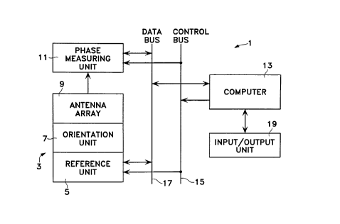
20 The a~dlus 1 for pl~ ir;,~g the method of calibration described above is shown in Fig.
13. The inertial reference system 3 COIlsi~ of the reference unit S and the orientation unit 7.
The r~fe.cllce unit 5 provides the means for establishing a three-axis inertial lcfclence
coordil~alc system and for ~ the cool-lilldlc system in a specifiPd oli~-lL~Lion relative
to the local geodetic coordinate system. The reference system 5 also provides its orientation
25 relative to the inertial lcrercllce coo~hlate system. The techniques for ~elro,~ g these
function are well-known in the art and will not be detailed here.
The oli~ ion unit 7 is ~tt~rhPd to the IcÇc-cl,ce unit and contains mPrh~ni.~ that permit
the orientation unit 7 to assume any specified orientation relative to the inertial reference
coor~hlate system. Here also, the techniques for performing this function are numerous and
30 well-known in the art and will not be detailed here.
The ~nt~nn~ array 9 is fixedly att~rhPd to the orientation
2174318
WO 96/08851 PCT/US95/12038
unit 7. The radio signals received by each al~le~ a in the array are separated by filtering or
other ~)pîU~Jlia~C procedures and the phase of the carrier of each radio signal is measured by
the phase llleasulillg unit 11.
Overall control of the ~ya~alus 1 is exercised by the conlpulcr 13. The CO~ . 13issues c~,.. -A.. As to the inertial l~r.,lGllce system 3 and the phase mea~ulc~le-.l unit 11 by
means of the control bus 15 and l~CCCi~Gs or trAncmitc data by means of the data bus 17. The
user of the a~al~lus 1 introduces programs, data, and co~ lC into the coln~ulel 13 and
obtains status i~ AtiO~ and data from the colll~ulcl by means of the input/output unit 19.
The flow ~ rAm for the program that controls the operations of the c~nl~ulel 13 is shown
10 in Fig. 14. The user initi~tto~C the process in step 25 by means of the input/output unit and in
step 27 provides (1) the position of the app~alus 1~ (2) the number M of radio-wave sources
to be used in caliblalillg the A~ 1 array 9 together with the positions of the radio-wave
sources, (3) the receiving channel in the phase measuring unit 11 to be AC.Cignto(l to each radio-
wave source together with tuning and sel~cti~n data for each channel, (4) the orientation of the
15 reference unit 5 in local geodetic coordinates, (5) the orientation of the inertial r,f~le.lce
cool~lillate system relative to the local geodetic coordinate system, and (5) the number N of
~1 ;r~ ;0~C to be used in calil~lalh-g the Alllrlll-~ array together with the data ~eciryhlg each
orientation in the inertial reference coordinate system.
The c~ . 13 aligns the inertial l~Ç~lGllce coor~il~Le system in the specified orientation
20 relative to the local geodetic coordi-~te system in step 29.
The index n is set equal to 1 in step 31 and in step 33 orientation data for orientation #n
is Ll~ rcl to the lefelellce unit 5 which causes the olicll~tion unit 7 to assume the specified
oliGlllation.
In step 35 the C(~ l 13 waits for a pre~ r~ d time sufficient for the a.llelma array
25 to be plopelly oriented and for the phases of the received radio waves to be measured.
In step 37 the colll~ulel 13 obtains the phase data from the phase measuring apparatus.
In step 39 the colll~ult;l 13 tests the value of n to see if it equals N, the number of oriGlllations
to be used in the calibration process. If it does not, it illClGlllellL~ n in step 41 and repeats steps
33-39.
30 If n equals N, the co..l~ el 13 c~lr~ t~s the orientation errors of the ~ntt~nn~ array in step
43. This data is available to the user via the input/output unit 19. The process is termin~ted
WO 96/08851 2 1 7 4 3 1 8
at step 45. PCTIUS95/t2038
12