Note: Descriptions are shown in the official language in which they were submitted.
WO 96/13676 PCT/US94/14318
-1-
TITLE OF THE INVENTION
RIGID SHEET POLYTETRAFLUOROETHYLENE MATERIAL
BACKGROUND OF THE INVENTION
1. Field of the Invention
The present invention relates to chemically resistant gasket material,
and particularly stiffened fluoropolymer gasket materials.
2. Description of Related Art
Expanded polytetrafluoroethylene (PTFE) is widely employed today in
a variety of gaskets and other sealing applications. As is disclosed in United
States Patent 3,953,566 to Gore, this material has numerous properties
making it highly desirable as a gasket, including: being readily compressible
and conformable; being chemically resistant; having relatively high strength;
and being far less prone to creep and loss of sealing pressure than full
density
PTFE. Gaskets made from PTFE are commercially available from a number of
sources, including W. L. Gore 8 Associates, Inc., Elkton, MD, under the
trademark GORE-TEX~, Inertech, Inc., Erlanger, KY, under the trademark
INERTEX~ and Garlock, Inc., Palmyra, NY under the trademark GYLON~.
While gaskets formed from pure expanded PTFE perform very well in
many gasket applications, these gaskets have a number of deficiencies. One
problem with this material is that it is extremely flexible. This flexibility
makes
the gasket difficult to handle and/or install in many instances, especially
where
sealing surfaces are in awkward locations or where the gasket may be prone
to bending or folding during installation.
A number of solutions have been proposed to address these problems.
Some manufacturers have attempted to stiffen the expanded PTFE material
by attaching the expanded PTFE to a stiff substrate of metal or similar
material. While a metal substrate improves handling characteristics, it tends
to
constrain possible uses for the gasket, leaving the substrate material subject
to attack by harsh chemicals or other environmental factors. One gasket of
this type employing a stainless steel core is available from M8P Manufacturing
Inc., Freeport, TX, under the trademark TEPHONIC~.
Gartock Inc. has attempted a similar approach with its ENVELON~
gasket. In this instance, the gasket comprises a compressible outer layer
containing microballons surrounding a solid, sintered PTFE material in its
WO 96/13676 PCTIUS94I14318
_2_
middle to prevent media permeation and blowout. This material is apparently
disclosed in United States Patent 4,900,629 to Pitolaj. However, since the
microballons in the ENVELON~ gasket are not made of PTFE, the gasket may
not be as chemically resistant as may be desirable.
Another approach attempted by some has been to load the expanded
PTFE material with a filler that supplies some limited rigidity. Examples of
fillers placed into some gasket materials that may supply some limited
rigidity
include glass microspheres and inorganic microspheres, such as silica and
fiberglass. While limited additional rigidity can be supplied in this manner,
these fillers tend to diminish the overall performance of the gasket material--
limiting chemical or temperature resistance or other qualities.
Still another solution to the problem of insufficient rigidity has been
developed by W. L. Gore 8~ Associates, Inc., in its insertable GORE-TEX~
gasket product. This gasket comprises a ring gasket constructed entirely from
expanded PTFE that has a raised sealing surface and a densified area next to
the sealing surface that supplies rigidity to the gasket. As such, the gasket
has the advantages of PTFE, such as chemical resistance and good sealing
characteristics, while being far easier to install in many applications.
Unfortunately, the structure that provides the improved handling
characteristics of the insertable GORE-TEX~ gaskets restricts their use in
other sealing applications. Insertable gaskets are selectively densified
during
manufacture to achieve rigidity. As such, these gaskets are not capable of
ready modification by the user. Further, unless mounted under high stress,
these gaskets do not supply a wide sealing area over the entire gasket face.
Conventional expanded PTFE sheet gasketing, however, may be trimmed and
modified by the user to address particular sealing needs. Another advantage
of these gaskets is that the entire gasket material placed between sealing
surfaces serves as a seal.
Accordingly, it is a primary purpose of the present invention to provide
a sealing material with the operating advantages of PTFE while being
sufficiently rigid so that it can be easily handled and installed.
It is a further purpose of the present invention to provide a rigid PTFE
sealing material that has a wide, conformable sealing surface.
It is another purpose of the present invention to provide a rigid PTFE
sealing material that can be supplied in a sheet or other form that can be
readily customized by a user without compromising gasket integrity.
These and other purposes of the present invention will become evident
from review of the following specification.
~1~~~~1
WO 96/13676 PCT/US94/14318
-3-
SUMMARY OF THE INVENTION
The present invention is an improved material suitable for gasketing
and other sealing applications. The sealing material of the present invention
comprises a composite sheet of flexible conformable polytetrafluoroethylene
(PTFE) layers bonded to at least one embedded layer of densified expanded
PTFE material. The composite material is quite rigid while retaining the
advantages of conventional expanded PTFE material, such as chemical
resistance, strength, ease of sealability and customization, and wide
effective
sealing areas.
The rigidity of the sealing material of the present invention allows the
material to be easily handled and installed without the difficulty associated
with
excessively flexible gasket products. The use of conformable outer layers
provides good sealing properties, permitting the sealing material to fill gaps
and imperfections on or between sealing surfaces. The embedded rigid
material assures that the sealing material will retain its position during
handling, cutting, and mounting without the problems a "floppy" gasket
material may encounter. Additionally, the material of the present invention is
of a consistent character across its entire sealing surface, allowing the
material
to be cut or modified into a wide variety of shapes and assuring maximum
effective sealing area between sealing surfaces.
DESCRIPTION OF THE DRAWINGS
The operation of the present invention should become apparent from
the following description when considered in conjunction with the
accompanying drawings, in which:
Figure 1 is a three-quarter isometric view of one embodiment of a
composite sealing material of the present invention;
Figure 2 is a three-quarter isometric view of a second embodiment of a
composite sealing material of the present invention;
Figure 3 is a front elevation view of a test rig used to measure the
rigidity of the composite sealing of the present invention;
Figure 4 is a side elevation view of the test rig of Figure 3;
Figure 5 is a three-quarter isometric view of a test sample of gasket
material of the present invention suitable for testing on the test apparatus
of
Figure 3.
CA 02174451 2000-02-07
-4-
DETAILED DESCRIPTION OF THE INVENTION
The present invention is an improved stiffened expanded
polytetrafluoroethylene (PTFE) material that retains the desirable operative
properties of expanded PTFE, while being suffiuentiy rigid to permit ease in
handling and installation. The present invention is particularly suitable for
use
in gaskets and other sealing applications, and especially those where user
modification of the sealing material is desired.
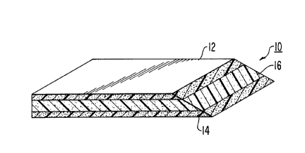
Shown in Figure 1 is a first embodiment of a rigid PTFE sheet gasket
material 10 of the present invention. This sheet material 10 comprises
external layers 12, 14 of a porous, expanded PTFE membrane and a core
material 16 of a higher rigidity PTFE membrane.
The external layers 12, 14 are constructed from a flexible, conformable
material, such as that made in accordance with United States Patent
3,953,566 to Gore. Preferably, these layers are
chemically inert and are conformable to sealing surfaces. Particularly
preferred is an expanded PTFE material such as that commercially available
from W. L. Gore 8 Associates, Inc., under the trademark GORE-TEX GR~
sheet gasket. This material comprises a flexible sheet having a thickness
ranging from 0.0254 to 25 mm, a void volume of 40 to 85%, a longitudinal
tensile strength of about 22 to 38 MPa and a transverse tensile strength of
about 11 to 22 MPa. This material is soft to touch and will readily conform to
imperfections in sealing surfaces.
Layer 12, 14 may be attached to the core material 16 in any suitable
manner inGuding by using an adhesive material, through melting, or other
bonding method. Suitable adhesives for use with the present invention inGude
an ePTFE saturated with an adhesive polymer, such a fluorinated ethylene
propylene (FEP), perfluoroalkoxy polymer (PFA) or other film, liquid, powder
or
rigid structure that may be used to establish a bond. Alternatively or
additionally, an effective bond may be formed by melting the two layers 12, 14
into core 16. This may be accomplished by raising the temperature to or near
the melt temperature of the fluoropolymer (e.g., about 327 to 382°C for
PTFE)
and applying sufficient pressure to adhere the surfaces together, (e.g.,
pressures of 20 to 6000 kPa).
The rigidity of the present invention is supplied by core 16. This
material should be sufficiently stiff that the gasket will not "flop' when
held on
edge. Moreover, unlike previous attempts to embed a stiffener material such
as some metal, the core 18 comprises a fluoropolymer material that has the
CA 02174451 2000-02-07
same chemical properties as the external layers 12, 14. Preferably, the core
material 16 is an expanded PTFE layer that has a higher rigidity than the
outer layers 12, 14. Most preferably, the core 16 for a 1.59 mm thick type
sheet gasket, is formed from a densified expanded PTFE made in the
following manner:
(a) layerins one or more sheets of porous expanded PTFE film on
a plate that can withstand temperatures exceeding 380°C and pressure up
to
1.72 MPa (250 psi). Preferably, 80 to 120 layers of such material are
employed, each layer comprising a thickness of 0.038 mm prior to treatment;
(b) laying a second plate over the top of the film layers;
(c) placing the two plates containing the expanded PTFE sheets
inside a bag made of polyimide film or other flexible film stable for several
hours at temperatures as high as 380°C;
(d) fitting the bag with a hose connection and placing the assembly
in an autoclave;
(e) drawing a vacuum inside the bag and gradually raising the
temperature and pressure inside the autoclave over a period of time until
reaching the sintering temperature of the expanded PTFE and a pressure
between 1.0 and 2.4 MPa (150 - 350 psi), and preferably between 1.4 and 1.7
MPa (200 - 250 psi);
(f) after a suitable time between about 10 minutes and 4 hours,
cooling the autoGave while gradually reducing the pressure;
(g) removing the bag from the autoclave, and removing the
densified expanded PTFE sheet from the bag and plates.
Once core 16 is formed, each of the external layers 12, 14 are
positioned around the core 16 and the structure is then laminated together
into
the gasket material 10 of the present invention. Preferably, the gasket 10 for
a
1.59 mm thick type sheet gasket, is formed in the following manner:
(1) The following materials are stacked on a stainless steel
autoclave Gaul plate in this order.
0.15 to 0.36 mm GORE-TEX GR~ sheet gasketing
1.0 to 1.3 mm fully densified ePTFE made in accordance with
the above description;
0.15 to 0.36 mm GORE-TEX GR~ sheet gasketing.
All caul plates should be treated with mold release, such as~ELEASE-ALL 50
mold release from Air Tech International Inc., to prevent sticking.
(2) A second stainless steel autoGave caul plate, equal in
dimensions to the first, is placed on top of the materials.
~ Trade-mark
21~~~51
WO 96/13676 PCTIUS94/14318
-6-
(3) The above combination of materials and Gaul plates are placed
onto a vacuum-ready, stainless steel, autoclave carrier plate. The materials
are positioned so that they are against the vacuum tube of the carrier plate.
(4) The top Gaul plate is covered with a piece of polyimide film
equal in length and width to the Gaul plates to prevent the adhesion of the
breather cloth described below to the Gaul plate. This minimizes the cleaning
and ease of removal of the Gaul plate after a process cycle.
(5) The polyimide film is covered with a piece of fiberglass breather
Goth. The breather cloth should be of a suitable porosity so as to permit the
flow of air during the autoclave cycle. The cloth should also withstand a
temperature of 370°C for approximately 4 hours. The size of the
breather
Goth should be such that it drapes over the materials beneath it, the carrier
plate vacuum tube, and onto the carrier plate. Ultra high temperature (UHT)
fiberglass breather cloth from Air Tech International, Inc. may be utilized in
this
process.
(6) The form-in-place sealant is placed along all edges of the
breather cloth. The ends of the sealant are overlapped.
(7) The breather cloth and sealant are covered with a continuous
piece of polyimide film. The film should cover all of the breather cloth and
sealant. It should exceed all edges of the sealant by approximately 25 mm.
This will assure an appropriate seal between the polyimide film and the Gaul
plate.
(8) Additional quantities of sealant are inserted at the sealant
comers (i.e., the comers of the package) to ensure a seal is maintained
between the polyimide film bag and the Gaul platen.
(9) The polyimide film is secured to the sealant by pressing the film
onto the sealant by hand. A successful package will allow air to travel in and
out of the package through the vacuum line only.
(10) A vacuum line which draws a vacuum over the carrier plate is
connected to a test vacuum pump for a period of ten minutes which permits
sufficient time to lower the pressure approximately 760 mm (30 in) Hg within
the polyimide bag. An impregnation vacuum pump, such as that
manufactured by BUEHLER Inc., may be used. The vacuum in the bagged
system may be monitored using a vacuum gauge such as that manufactured
by Marshal having ~ 6.9 kPa precision. After 10 minutes, the test vacuum
pump pressure is separated from the carrier plate by closing a valve between
the vacuum gauge and the vacuum pump. A test period of two minutes is
used to determine whether or not a sufficient seal is created within the
~ 174451
WO 96/13676 PCT/US94/14318
_7_
polyimide bagged system and the carrier caul plate. A sufficient seal is
indicated by no movement in the vacuum gauge after the completion of the
two minute test period.
(11) After determining that there is no apparent vacuum leaks within
the bagged system, a high temperature adhesive backed polyimide tape is
applied to the edges of the polyimide covering. The comers were taped
thoroughly so that the film is not pulled away from the sealant in the
autoclave.
(12) The test vacuum pump, vacuum gauge, and vacuum line
assembly are disconnected from the carrier plate.
(13) The carrier plate and its contents are placed into the autoclave.
A carrier plate vacuum line is connected to a vacuum port in the pressure
chamber of the autoclave and the autoclave door is secured.
(14) The vacuum line is removed from the vacuum pump outside of
the pressure chamber to open the package to the outside atmosphere.
(15) A preprogrammed autoclave cycle is run with the following
parameters, concurrently:
Temperature: 370°C
Ramp - 15 minutes
Soak - 45 minutes
Pressure: 34.5 kPa (5 psi)
Ramp - Immediate
Soak - 60 minutes
(16) When the run is complete, the autoclave is opened, the carrier
plate vacuum line is disconnected from the autoclave vacuum port, and the
carrier plate is removed immediately, hence no set cool-down period is
maintained before removing the caul platen to ambient temperature.
(17) All polyimide film and breather cloth are removed from the
carrier plate. The top Gaul plate is removed from the material. The material
is
immediately removed from the carrier plate and placed between two ambient
temperature Gaul plates (equal to or greater than its length and width) to
promote quick cooling.
(18) The material is removed from the caul plates after 10 minutes.
(19) All used polyimide film, tape, breather cloth, and sealant are
discarded.
A densified expanded PTFE material, when laminated into a gasket of
the present invention, imparts the desired rigidity without compromising any
of
~~~~~51
WO 96/13676 PCT/US94114318
_g_
the chemical resistance or other desirable properties of expanded PTFE
gaskets.
It should be appreciated that skived PTFE may be used in place of the
fully densified expanded PTFE in the present invention. This material is
commercially available and may be prepared in the following manner:
Granular PTFE is molded into a solid cylindrical billet under heat and
pressure. (Typically, a temperature of about 330°C and a pressure of
about
34.5 MPa (5000 psi)). Vacuum is generally applied to the billet during molding
to assure absence of air pockets. Once cooled, the billet is then rotated
about
its axis and the desired thickness of material is skived or cut from the outer
surface into a continuous sheet. Optionally, the billet may be annealed to
reduce internal stresses and then rotated. The total width of the sheet is
dependent upon the billet height. The desired length of material is cut from
the continuous sheet produced.
A further embodiment of the present invention is shown in Figure 2. In
this embodiment, the gasket sheet material 18 comprises: outer layers 20, 22
of conformable PTFE material; rigid inner layers 24, 26 of rigid PTFE material
attached to each of outer layers 20, 22, respectively; and a center layer 28
of
conformable PTFE attached between each of the rigid inner PTFE material
layers 24, 26. Although the properties of each of the layers may be modified
to satisfy specific performance characteristics to the sheet 18, for most
applications the conformable layers 20, 22, and 28 should comprise a flexible
expanded PTFE material, such as that previously described. In the
embodiment shown, outer layers 20, 22 are approximately 0.006" (0.15 mm)
wide, and center layer 28 is approximately 0.034" (0.86 mm) wide.
Similarly, the rigid inner layers 24, 26 comprise a densified expanded
PTFE material, such as the core 16 previously described. Since two layers are
provided, each of these layers may be significantly reduced in thickness. As
shown, each of the rigid layers is approximately 0.010" (0.25 mm) thick.
This embodiment may be constructed in the same manner previously
described, only employing the following stock of material:
0.1 - 0.2 mm GORE-TEX GR~ sheet gasketing
0.2 - 0.3 mm Fully densified ePTFE
0.8 - 1.0 mm GORE-TEX GR~ sheet gasketing
0.2 - 0.3 mm Fully densified ePTFE
0.1 - 0.2 mm GORE-TEX GR~ sheet gasketing
It should be evident from the above description that the gasket of the
present invention may take a number of forms while retaining the advantages
WO 96/13676 PCT/US94/14318
_g_
of the present invention. By mounting conformable, expanded PTFE sheets
as the external surfaces of the gasket, the gasket of the present invention
retains all of the conforming and sealing properties of presently available
. expanded PTFE sheet gasketing. By then mounting one or more layers of a
stiffened expanded PTFE material in the core, the desired stiffness can be
imparted without compromising the sealability or chemical compatibility of the
basic fluoropolymer. Since the final gasket material may continue to be
provided in the form of a sheet, the gasket of the present invention may be
easily modified by the end user for particular applications, and the gasket
continues to have a~flat, wide effective sealing surface.
In order to quantify the degree of improved rigidity of the sheet material
formed in accordance with the present invention, a test apparatus 30 has been
developed as shown in Figures 3 and 4. This apparatus 30 comprises an up-
right backboard 32 having a clamp mechanism 34 and a pivot bar 36 attached
thereto. A test sample 38 of material to be tested is prepared in the manner
described below and is mounted in the clamp mechanism 34, forming a tight
constraint between clamp head 40 and landing 42. One or more studs 44a,
44b may be provided on the landing to assure exact orientation and secure
restraint of the test sample 38.
In operation, each test sample 38 is mounted in this apparatus 30 in
the manner shown, with the test sample extending outwardly from the clamp
mechanism 34 over pivot bar 36. Over time, the test sample 38 will distort
downwardly around the pivot bar 36 due to the effect of gravity on the
outwardly extending portion of the test sample 38. This effect may be
accelerated by placing a clip or other weight on the end of the sample 38. The
weight of the clip used in the testing was 12.5 grams.
The amount of rigidity of the test sample may then be recorded as the
degree of deflection downward over a given period of time. In the embodiment
of the test apparatus 30 shown, the backboard 32 includes a series of hatched
marks 46 thereon to allow for easy determination of the degree of down ward
deflection (i.e., extending from 0° (i.e., no movement) to 90°
(i.e., a complete
distortion straight down from the pivot bar 36)).
It is important that each piece of material to be tested by this apparatus
be prepared in a consistent manner. Shown in Figure 5 is one suitable
construction for the test sample 38. In this forth, the test sample 38
comprises
a strip of material 48 cut to approximately 266.70 mm in length and 38.10 mm
in width. Openings 50a, 50b are provided to interface with studs 44a, 44b. In
order to accelerate the downward distortion of the test sample, a weighted
clip
CA 02174451 2000-02-07
52 (e.g., one made from steel, lead, or similar materials) is provided to
removably attach to the end of each sample to be tested.
Test Results:
Comparative tests were performed on the material of the present
invention made in accordance with the construction of Figures 1 and 2 above,
as well as conventional gasket materials of GORE-TEX GR~ sheet gasketing
acquired from W. L. Gore 8~ Associates, Inc., Elkton, MD, and'GYLON 3504
acquired from Gariock Inc. The tests performed included creep relaxation
(ASTM F-38B), sealability (ASTM F-37), compressibility/recovery (ASTM F-36),
and rigidity (employing the test apparatus described above). The results are
summarized in the following table.
oaER~nNG
MATERIALTHIGCCREEP SEALA&I.fTYCOMPrRECRIGIOfTY TEMPERATURE
RELAXATION (DEGREES)
(1L)
NESS 23 37/500 (11) UMfTATIONS
C
100
C
MM Miadnch UNYYTD ('!1
pN) WTD
MPf
GORE-TEX1.0 22 4134.5
m
GR SHEET(.073)36.5 61.6 (3250 (627/ 14.0 75.0 315'C
/ 5000) 121)
GASI(ET1NG
RIGID
SHEET
(FIG. 1.4 21.57123.1
1 )
OF PRESEM(.066)10.1 55.0 (3173 (17.1 16.0 43.0 315'C
~NVEHTbN t 3100) I
26.0)
RIGID
SHEET
(~~c. 1.e lo.sr322
~
Of=PRESENT(.070)34.1 75.7 (263311666)(Z4.o131.~L0 t4.2 315
INVENTION
GvLONe 1.6 17.6130.3
3'04 (.O6?)33.8 66.3 Q36011400)(36.0130.0)20 t2.7 260
The specific test parameters for each of these tests are set forth below:
Test Method for Compressibility and Recovery
ASTM F-36 is a standard test method for measuring the compressibility
and recovery of gasketing materials. The test fixture utilized consisted of a
6.35 mm (114") diameter penetrator pin, dial indicator, load transfer
assembly,
air cylinder, and pressure regulator. The penetrator pin is connected to the
load transfer assembly and its movement measured by the dial indicator.
Load is applied pneumatically and is controlled by an air regulator. The test
method was performed in the following manner
1. Acquire or cut a test specimen approximately 12.70 mm (1/2") diameter.
2. Measure and record the test specimen thiGcness.
* Trade-mark
WO 96/13676 PCTIUS94/I4318
-11-
3. Zero the dial indicator.
4. Center the test specimen beneath the penetrator pin. Using the air
regulator pre-load the material to 0.69 MPa (100 psi) for 15 seconds.
Measure and record the pre-load thickness after 15 seconds.
5. Apply the major load of 17.25 MPa (2500 psi) for 1 minute. Measure and
record the major load thickness after 1 minute.
6. Remove the major load but leave the test specimen in the fixture.
7. Wait 1 minute and record the recovery thickness.
8. Remove test specimen from test fixture. Discard test specimen.
9. Compressibility is calculated by the following equation:
pre-load thickness - major load thickness x 100
pre-load thickness
10. Recovery is calculated by the following equation:
recovery thickness - major load thickness x 100
pre-load thickness - major load thickness
Test Method for Sealability
ASTM F-37 is a standard test method for testing the sealability of
gasketing materials. The test method was performed in the following manner:
1. Cut a 39.69 mm (1 9/16") LD. x 58.74 mm (2 5116") O.D. (1471.06 mm2
(2.28 inZ)) test specimen. ASTM documentation requires a 31.75 mm (1
1l4") LD. x 44.45 mm (1 3/4") O.D. (722.62 mm2 (1.12 in2)) test specimen.
2. Measure and record the thickness of the test specimen.
3. Center the test specimen between two 152.40 mm x 152.40 mm x 25.4 mm
(6" x 6" x 1 ") steel test platens with surface finishes ranging from 32 - 500
microinch (0.8 - 12.7 miuometers). One platen must be blind and the
other machined to allow for pressurization. Record surface finish.
4. Connect a pressurization device to a manometer and the test platens.
5. Place the platens into a pressurization fixture.
6. Apply an external force until the stress on the gasket is equal to 3.5 MPa
(500 psi).
7. Pressurize (internally) the test platens to 0.21 MPa (30 psi) with ambient
air.
8. Isolate one side of the manometer by closing the isolation check valve on
the manometer. (One side of the manometer will monitor the constant
~-~ 1~~~~
WO 96/13676 PCT/US94l14318
-12-
applied pressure of the pressurization device and the other pressure decay
if present.)
9. Note any change in the manometer level. A change in the manometer
level is an indication of a leak or lack of seal.
10. If no change is noted after 1/2 hour, the material under pressure is
considered sealed. Measure and record the external load on the test
platens. If the level of the manometer has changed increase the gasket
stress load by 0.69 - 3.50 MPa (100 - 500 psi). Incremental loading is
determined by operator experience. After 1/2 hour note any change in
manometer level.
11. Continue until an effective seal is established. Record the external load
responsible for the seal.
12. Remove the internal pressure from the test platens. Remove the external
load from the system. Remove test specimen from the fixture. Discard
test specimen or save for further documentation.
Test Method for Compressive Creep Relaxation
ASTM F-38 is a standard test method for testing the compressive creep
relaxation of gasketing materials. The test method was performed in the
following manner:
1. Cut a 33.34 mm (1 5/16") LD. x 50.80 mm (2") O.D. (1129.10 mm2 (1.75
inZ)) test specimen. ASTM documentation requires the test specimen to
have a surface area of approximately 1290.40 mm2 (2.0 in2).
2. Center the test specimen between two 12.70 mm (1/2") LD. x 76.20 mm
(3") O.D. x 25.4 mm (1") thick steel test platens with 16 - 32 microinch (0.4
- 0.8 micrometers) surface finishes.
3. Complete the fixture assembly with a UNF grade 3/8"-24 calibrated bolt
approximately 76.2 mm (3") long with a floating pin center, washer, and
nut. The floating pin is affixed only to the bolt head and permitted to float
down the inside shaft of the bolt. Place the bolt through the inside
diameters of the test platens. Place the washer and nut on the end of the
bolt.
4. Tighten the nut on to the bolt finger tight. Stop when the nut and washer
are restrained against the test platen.
5. Restrain the head of the bolt. Place a 9/16" wrench about the nut and
attach a dial indicator to the end of the bolt. Spin the indicator clock-wise
onto the bolt until finger tight.
11 x'445 ~
WO 96/13676 PCT/US94/14318
-13-
6. Determine desired gasket stress. (20.7 MPa (3000 psi))
7. Determine the respective load (2,386 kg ((5,250 Ib.)) required to develop
the desired gasket stress.
8. Consult the bolt calibration load vs. elongation chart for the necessary
bolt
elongation required to impart the necessary load. Record the required bolt
elongation or initial deflection.
9. Set the dial indicator to match the initial bolt elongation or deflection.
10. Rotate the nut clockwise using the wrench until the dial indicator reaches
zero. This load or bolt elongation should be imparted within a 15 second
period of time.
11. Remove the dial indicator and the wrench.
12. Place the fixture in an elevated temperature environment if desired.
13. The test runs for approximately 24 hours. If tested at an elevated
temperature remove the fixture from the high temperature environment
after 22 hours. Allow to cool for 2 hours.
14. Restrain the head of the bolt as done before. Place a 9/16" wrench about
the nut and attach the dial indicator to the end of the bolt as done before.
15. Set the indicator to zero.
16. Rotate the nut counter-clockwise using the wrench until the indicator dial
stops moving.
17. Record dial indicator reading. This is the final or remaining bolt
elongation.
18. Disassemble the test fixture and discard the test specimen.
19. Compressive creep relaxation is calculated by the following equation:
Initial Deflection - Final Deflection x 100
Initial Deflection
Test Method for Rigidity
Rigidity was measured by placing a standard die cut sample (figure 5) of
the material into the test fixture (figure 3 8 4), clamping it into place
horizontally, and allowing it to remain cantilevered 190.5 mm (7 1/2") under
its
own weight for 1 112 minutes. The test fixture is graduated in five degree
intervals with a total range of 90 degrees. After 1 1/2 minutes of
cantilevering
record the materials deflection in degrees. Each test sample is then loaded at
its free end with a 12.5 gram clip (figure 5) and retested in the same manner.
Test samples are 38.10 mm (1 1/2") wide x 266.70 mm (10 1/2") long with two
9.53 mm (3/8") locating holes 12.70 mm (1/2") and 38.10 mm (1 1/2") from one
end.
~'~--~~~51
WO 96/13676 PCT/US94114318
-14-
The material of the present invention provides sufficient rigidity that it
can be easily handled and installed. Since rigidity is provided by embedded
densified expanded PTFE material, a composite sheet of the present invention
may be readily cut into virtually any desired shape without particularly
compromising the sealability or rigidity of the material. For most
compositions,
the material of the present invention may be cut using a blade, die, or other
suitable means.
Additionally, unlike previous PTFE gaskets that achieved rigidity
through selective densification of certain surface areas of the gasket face
(i.e.,
diminishing the sealability of those areas), the material of the present
invention
provides an even sealing area across its entire face. This assures more
reliable and consistent contact between sealing surfaces while, again,
permitting far greater freedom in gasket modification.
Finally, since the material of the present invention comprises PTFE
throughout, it does not have the limitations found with previous materials.
Accordingly, the material can withstand operating temperatures up to
315°C
(600°F). Other stiffened gasket materials, such as BLUE GYLON~ Style
3504
gasketing and ENVELON~ Style 3565 gasketing contains additives that limit
its effective operating temperature range (e.g., to the neighborhood of
260°C
(500°F)).
EXAMPLE I
A three part construction of the present invention was produced in the
following manner:
(1) The following materials were stacked on a 1.6 mm thick by 406
mm widE by 660 mm long stainless steel autoclave caul plate in this order:
0.51 mm thick (cut to the area of 406 mm wide by 660 mm long
using conventional shears) GORE-TEX GR~ sheet gasketing Model #
GR0.05 available from W. L. Gore and Associates, Elkton, MD
3.18 mm thick (cut to the area of 406 mm wide by 660 mm long
using conventional shears) conventional full density skived PTFE available
from McArdle Desco Corporation, New Castle, Delaware
0.51 mm thick (cut to the area of 406 mm wide by 660 mm long
using conventional shears) GORE-TEX GR~ sheet gasketing Model # GR0.05
available from W. L. Gore and Associates, Elkton, MD.
CA 02174451 2000-02-07
-15-
All Gaul plates are of similar dimensions and all were treated with
RELEASE-ALL 50 mold releasing agent available from Air Tech International
Inc., to prevent sticking.
(2) A second stainless steel autoclave Gaul plate was placed on top
of the materials keeping the same width and length orientation as the other
Gaul plate and materials.
(3) The above combination of materials and Gaul plates were then
placed onto a vacuum ready, stainless steel, autoclave carrier plate. The
materials were positioned so that they were against the vacuum tube of the
carrier plate.
(4) The top caul plate was covered with a piece of 0.051 mm thick
polyimide fiIm~KAPTON available from E. I. Du Pont de Nemours Company,
Wilmington, Delaware) equal in length and width to the Gaul plates.
(5) The polyimide film was covered with a piece of an ultra high
temperature (UHT) fiberglass breather Goth from Air Tech International, Inc..
The breather Goth was of a suitable porosity so as to permit the flow of air
during the autoGave cycle. The breather Goth was cut to a size such that it
draped over the materials beneath it, inGuding the carrier plate vacuum tube,
and a 10 to 20 mm portion around the perimeter of the base Gaul plate laying
on the carrier plate.
(6) A silicone form-in-place autoGavable sealant was placed along
all edges of the breather Goth in a continuous fashion. The ends of the
sealant were overlapped to create a Gosed loop of sealant in the plane of the
carrier plate.
(7) The breather Goth and sealant were covered with a piece of
polyimide film. Care was taken so that the polyimide film covered all of the
breather Goth and sealant and that the polyimide film exceeded all edges of
the sealant by approximately 25 mm. This was done to assure there exists
suffiuent slaGc film material so that a seal between the polyimide film and
the
caul plate could be maintained during the autoGave cyGe.
(8) Additional quantities of sealant were inserted at the sealant
comers (i.e., the comers of the package) to ensure a seal between the
polyimide film bag and the caui platen.
(9) The polyimide film is secured to the sealant by pressing the film
onto the sealant by hand. A successful package will allow air to travel in and
out of the package through the vacuum line only.
(10) A vacuum line which draws a vacuum over the carrier plate is
connected to a test vacuum pump for a period of ten minutes which permits
~ Trade-mark
~~~~~1
WO 96/13676 PCT/US94/14318
-16-
sufficient time to lower the pressure approximately 760 mm (30 in) Hg within
the polyimide bag. An impregnation vacuum pump, such as that
manufactured by BUEHLER Inc., may be used. The vacuum in the bagged
system may be monitored using a vacuum gauge such as that manufactured
by Marshal having ~ 6.9 kPa precision. After 10 minutes, the test vacuum
pump pressure is separated from the carrier plate by closing a valve between
the vacuum gauge and the vacuum pump. A test period of two minutes is
used to determine whether or not a sufficient seal is created within the
polyimide bagged system and the cartier Gaul plate. A sufficient seal is
indicated by no movement in the vacuum gauge after the completion of the
two minute test period.
(11) After determining that there is no apparent vacuum leaks within
the bagged system, a high temperature adhesive backed polyimide tape is
applied to the edges of the polyimide covering. The comers were taped
thoroughly so that the film is not pulled away from the sealant in the
autoclave.
(12) The test vacuum pump, vacuum gauge, and vacuum line
assembly are disconnected from the carrier plate.
(13) The carrier plate and its contents were carefully placed into the
autoclave. A 6.35 mm inside diameter vacuum line was connected to the
carrier plate and to a vacuum port in the pressure chamber of the autoclave
and the autoclave door was closed and secured.
(14) The vacuum line leading from the port within the vacuum
chamber is permitted to vent to atmospheric pressure (i.e., the inside of the
polyimide bagged system was vented at atmospheric pressure.
(15) The autoclave cycle was programmed to run at the following
parameters for inside the vessel's chamber concurrently:
Temperature: 370°C
Ramp - 15 minutes
Soak - 45 minutes
Pressure: 34.5 kPa (5 psi)
Ramp - Immediate
Soak - 60 minutes
(16) The autoclave was opened after completion of the autoclave
cycle. The carrier plate vacuum line was disconnected from the autoclave
vacuum port, and the carrier plate was removed immediately, hence no set
cool-down period was maintained before removing the caul platen to ambient
temperature.
WO 96/13676 PCT/US94/14318
-17-
(17) All polyimide film and breather cloth were removed from the
carrier plate. The top Gaul plate was removed from the material. The material
was then immediately removed from the carrier plate and placed between two
Gaul plates (equal to or greater than its length and width) at ambient
temperature thus facilitating a fast cool-down period.
(18) The material was removed from the caul plates after 10
minutes.
(19) All used polyimide film, tape, breather cloth, and sealant were
discarded.
The resulting structure was a three layered bicomponent sheet material
which had soft or conformable outer surfaces but yet rigid to flexure thus
making it very useful as a gasketing material. It is especially useful for cut
gaskets having thin cross-sectional areas since it is advantageous to the
gasket user, that the gasket not flex during gasket placement. The present
invention provides a gasketing material which is both conformable and rigid to
flexure.
EXAMPLE II
A five part construction of the present invention was produced using
the method of manufacture as outlined in EXAMPLE I, the following materials
were stacked on a 1.6 mm thick by 406 mm wide by 660 mm long stainless
steel autoclave Gaul plate in this order:
0.2 mm thick (cut to the area of 406 mm wide by 660 mm long
using conventional shears) GORE-TEX GR~ sheet gasketing Model #
GR0.02 available from W. L. Gore and Associates, Elkton, MD
0.25 mm thick (406 mm wide by 660 mm long) fully densified
expanded PTFE as described below
0.88 mm thick (cut to the area of 406 mm wide by 660 mm long
using conventional shears) GORE-TEX GR~ sheet gasketing Model # GR32
available from W. L. Gore and Associates, Elkton, MD
0.25 mm thick (406 mm wide by 660 mm long) fully densified
expanded PTFE as described below
0.2 mm thick (cut to the area of 406 mm wide by 660 mm long
using conventional shears) GORE-TEX GR~ sheet gasketing Model #
GR0.02 available from W. L. Gore and Associates, Elkton, MD.
~~ ~~51
WO 96/13676 PCT/US94/14318
-18-
The 0.25 mm thick, fully densified expanded PTFE was produced using
the following method:
A section measuring 406 mm wide by 660 mm long was cut using
conventional shears from a 1219 mm wide by 1422 mm long sheet of 1 mm
thick GORE-TEX GR~ sheet gasketing Model # GR32 available from W. L.
Gore and Associates, Elkton, MD.
The cut section was placed on a 1.6 mm thick by 406 mm wide by 660
mm long stainless steel platen called a cauf platen. A second stainless steel
Gaul platen similar in dimensions was placed on top of the cut section
maintaining the length and width orientation of all sections. Both Gaul plates
were treated with RELEASE-ALL 50 mold releasing agent available from Air
Tech International Inc., to prevent sticking.
The Gaul platen- GORE-TEX GR~ sheet gasketing-Gaul platen
assembly was then placed on a carrier plate for an autoclave. A vacuum bag
made of 0.051 mm thick KAPTON polyimide film available for E. I. Du Pont de
Nemours Company, Wilmington, Delaware, was made such that a vacuum can
be drawn through the carrier plate and thus over the caul platen-GORE-TEX
GR~ sheet gasketing-Gaul platen assembly. To aid in the removal of
entrapped air within the gasket material and also minimize the chance of the
Gaul platen from piercing the polyimide vacuum bag during the autoclave
cycle, a piece of an ultra high temperature (UHT) fiberglass breather cloth
from Air Tech International, Inc., was cut to a size such that it draped over
the
Gaul platen assembly. The cut size was such that, when draped over the
assembly, the breather cloth covered the carrier plate vacuum tube, and a 10
to 20 mm portion around the perimeter of the base caul plate laying on the
carrier plate.
The polyimide film was cut oversized such to cover the Gaul platen
assembly by approximately 20-35 mm around the perimeter of the assembly.
A silicone autoclavable caulk or sealant was placed along the edges of the
breather cloth in a continuous fashion having the ends of the silicone sealant
or caulk overlapped to create a closed loop of the sealant in the plane of the
carrier plate.
The polyimide film was then carefully pressed down along its perimeter
on to the silicone caulk by the hand. The four comers were gathered by the
natural folding of the poiyimide film and additional silicone caulk was placed
WO 96/13676 PCT/US94/14318
-19-
inside the edges of the folds and pressed together by hand pressure as well,
thus creating a closed structure.
The vacuum bagged assembly laying on the carrier plate was placed
into an autoGave. A vacuum was drawn to at least 630 mm of Hg inside the
polyimide caul platen assembly thus subjecting the GORE-TEX GR~ sheet
gasketing to the vacuum.
The assembly then was subjected to the following temperature and
pressure (concurrent) operation:
Temperature:
Ramp 1 - at ambient Temperature - 10 minutes
Ramp 2 from ambient to Temperature = 370°C - 40 minutes
Soak - 60 minutes
Ramp Down - 30 minutes
Pressure: 1.8 MPa
Ramp - 50 minutes
Soak - 60 minutes
Ramp Down - 30 minutes
Total duration = 140 minutes
After the autoclave operation, the carrier plate was removed from the
autoclaved and permitted to cool to ambient temperature before
disassembling. The resulting structure between the Gaul platens was a 0.25
mm thick, full density expanded PTFE sheet good. This process was run twice
such to produce two 0.25 mm thick (406 mm wide by 660 mm long) fully
densified expanded PTFE sheets. These two sheets were used as sheets
number 2 and 4 in the five layer stack lay-up of this example.
Following the manufacturing steps in accordance to EXAMPLE I, the
five layer-structure was produced which is suitable for an improved gasket
material. The rigidity to flexure was enhanced over the three-layer
construction of EXAMPLE I. The five layer sheet has improved stiffness over
the three layer construction sheet due to the placement of the higher Modulus
- of Elasticity (full density material) at an optimal distance from the
neutral
bending axis and reducing weight by minimizing the weight ratio of full
density
material to low density material.
WO 96/13676 PCT/US94114318
-20-
EXAMPLE III
An alternative construction of the present invention can be produced in
the following manner: The core material consisting of skived full density PTFE
in EXAMPLE 1 can be replaced by fluorinated ethylene propylene (FEP), or
perfluoroalkoxy polymer (PFA) or other film material possessing a stiffer
modulus of elasticity or flexural modulus than low density expanded PTFE.
By replacing the full density PTFE / ePTFE with equivalent thicknesses
of FEP or PFA materials in accordance to EXAMPLE I, the resulting sheet
gasket will be conformable on the outer surfaces and maintain a stiffness
which renders the sheet material favorable to be used as a gasket material.
Demonstrating equivalent rigidity to those materials produced with full
density
PTFE / ePTFE in EXAMPLES I and II, the overall chemical and thermal
resistance of this material will be less due to the lower chemical and thermal
properties inherent to FEP and PFA.
Example IV
Below is a contemplated example of a rigid but conformable organically
and or inorganically filled fluoropolymeric gasketing material which is
suitable
in applications requiring improved electromagnetic interference (EMI)
characteristics.
Electronic devices and housings of electronic components requiring
seals typically can not use standard seals or gaskets. Typical (common) seal
material such as rubber, paper or fluoropolymer seals do not conduct
electromagnetic energies very effectively. Problems or malfunctioning of the
electronics may result due to extraneous electrical waves, or energy if
typical
(common) sealing materials are used in these electronic applications.
A method to correct this EMI deficiency of common sealing medium is to
provide a sealing gasket material which is electrically conductive.
The gasket of the present invention can be altered such to make it useful
as a gasket for EMI applications. This improved rigid but conformable
gasketing material can be produced using a graphite filled (or other
electrically
conductive materials such as aluminum or gold etc.) expanded PTFE material
and coupling it with a graphite filled densified expanded PTFE in the manner
as disclosed in EXAMPLE I. Similar to the construction in EXAMPLE 1 except
that the raw expanded PTFE materials are loaded with an electrically
conductive material as taught in U.S. Patent 5,286,568 to Bacino and the
thinner outer conformable filled ePTFE materials as taught in U.S. Patent
CA 02174451 2000-02-07
-21-
4,985,296 to William P. Mortimer, Jr. The
electrically loaded materials can be added up to 6096 by weight into the
expanded PTFE matrix thus providing or tending to a matrix with isotropic and
enhanced electrical properties.
Moreover, the densified ePTFE filled material need not be filled to the
same loading of the electrically conductive material as the low density filled
expanded PTFE (i.e., the uncompressed ePTFE) since at full density, the
electrically conductive particles are in very Gose proximity and contact with
one another thereby decreasing the electrical resistance thus increasing the
electrical conductivity of the material matrix. Hence, the electrical
conductivity
of the full density material will be higher than the electrical conductivity
of the
compressible low density material at to same electrical conductive partite
loading. The electrical conductivity of the two materials will be similar when
the gasket material of the present invention is subjected to pressures greater
than 17.25 MPa (2500 psi) rendering the entire gasket to full density. If in
the
sealing application, a gasket Damping force of 17.25 MPa (2500 psi) or
greater is not necessary to reach a seal such as for low pressure liquid
medium, then the electrically conductive partite loading of the low density-
conformable ePTFE must be proportionally higher or greater than the loading
of the rigid loaded-densified ePTFE material to achieve similar electrical
conductivity between the two materials.
While particular embodiments of the present invention have been
illustrated and described herein, the present invention should not be limited
to
such illustrations and descriptions. It should be apparent that changes and
modifications may be incorporated and embodied as part of the present
invention within the scope of the following Gaims.