Language selection

Search

Patent 2174470 Summary

Third-party information liability

Some of the information on this Web page has been provided by external sources. The Government of Canada is not responsible for the accuracy, reliability or currency of the information supplied by external sources. Users wishing to rely upon this information should consult directly with the source of the information. Content provided by external sources is not subject to official languages, privacy and accessibility requirements.

Claims and Abstract availability

Any discrepancies in the text and image of the Claims and Abstract are due to differing posting times. Text of the Claims and Abstract are posted:

  • At the time the application is open to public inspection;
  • At the time of issue of the patent (grant).
(12) Patent: (11) CA 2174470
(54) English Title: IMPROVEMENTS IN QUICK CONNECTIONS
(54) French Title: AMELIORATIONS APPORTEES AUX RACCORDS RAPIDES
Status: Expired and beyond the Period of Reversal
Bibliographic Data
(51) International Patent Classification (IPC):
  • F16L 37/46 (2006.01)
  • F16L 37/413 (2006.01)
  • F16L 37/42 (2006.01)
(72) Inventors :
  • LACROIX, JEAN-JACQUES (France)
  • LAPORTE, CHRISTOPHE (France)
(73) Owners :
  • STAUBLI FAVERGES
(71) Applicants :
  • STAUBLI FAVERGES (France)
(74) Agent: MACRAE & CO.
(74) Associate agent:
(45) Issued: 2008-02-19
(22) Filed Date: 1996-04-18
(41) Open to Public Inspection: 1996-10-27
Examination requested: 2003-01-15
Availability of licence: N/A
Dedicated to the Public: N/A
(25) Language of filing: English

Patent Cooperation Treaty (PCT): No

(30) Application Priority Data:
Application No. Country/Territory Date
95.05240 (France) 1995-04-26

Abstracts

English Abstract

This invention relates to quick connections for removably coupling pipes, incorporating a valve and an O-ring, wherein the valve, its spring, a fixed ring and the seat or O-ring constitute an independent assembly which is mounted in the principal piece of the body of the female element. The rear piece of this body is fixed by elastically clipping tongues behind an annular projection.


French Abstract

La présente invention a trait aux raccords rapides qui servent à coupler des tuyaux de façon amovible et qui comprennent un clapet et un joint torique, le clapet, son ressort, une bague fixe et le siège ou joint torique constituant un ensemble monté séparément dans la pièce principale du corps de l'élément négatif. La pièce arrière de ce corps est fixée en place derrière une projection annulaire à l'aide de languettes d'attache élastiques.

Claims

Note: Claims are shown in the official language in which they were submitted.

-6-
WHAT IS CLAIMED IS:
1. Quick connection for removably coupling pipes, of the type in which a
tubular body of
a female element, constituted by a tight assembly of a principal piece and a
rear piece,
contains a valve which is associated with an O-ring forming seat and with a
closure spring
and which is brought into position of opening during fit of a male element in
said female
element, wherein the valve itself, an outer ring which surrounds it, the O-
ring which is borne
by a front end of this ring, and a spring which is maintained between the
valve and said ring,
form an independent assembly which, up to fastening of the rear piece of the
body, is
maintained axially in the axial bore of the principal piece, by friction of
the deformable wall
of the O-ring or seat against the smooth wall of said bore.
2. The connection of Claim 1, wherein the O-ring or seat comprises a
projecting annular
lip.
3. The connection of Claim 1, wherein a terminal face of the outer ring
comprises an
annular projection which cooperates with a corresponding annular cavity made
in the O-ring
to ensure centering thereof on the ring.
4. The connection of Claim 1, wherein the O-Ring ensures, by bearing and
gripping
between an outer shoulder of the ring and a terminal edge of the rear piece,
tight assembly of
the two pieces which form the body of the female element.
5. The connection of Claim 1, wherein the rear piece of the body of the female
element
is fixed in the principal piece by elastic clipping.
6. The connection of Claim 5, wherein an inner wall of the axial bore of the
principal
piece has longitudinal tongues cut out therein, oriented obliquely to be
elastically deformed
and applied against the periphery of the piece behind an annular projection
thereof.

Description

Note: Descriptions are shown in the official language in which they were submitted.


2174 4 70
-1-
FIELD OF THE INVENTION
The present invention relates to quick connection
devices used for the dismountable coupling of pipes,
and in particular to those which comprise two male and
female elements fixed at the ends of the pipes to be
connected and adapted to fit one in the other, provoking
automatic opening of a loaded valve provided inside the
female element.
BACKGROUND OF THE INVENTION
In known constructions, the body of the female element
is generally constituted by the tight assembly of two
tubular pieces, ordinarily screwed one in the other,
ensuring at the same time assembly of the valve and of
the closure spring which is associated therewith, which
valve, directly mounted in the core of the body, cooperates
with a seat formed by an 0-ring suitably retained inside
one-of the afore-mentioned pieces.
It will be readily appreciated that such a structure
does not lend itself well to automatic assembly employing
robots or manipulators. Furthermore, it will be recalled
that the shape and dimensions of the rear piece of the
body which is intended to be fastened to the end of a
pipe, vary as a function of the type of coupling envisaged,
which obviously complicates storage of the connections
if it is desired to have a wide range of products available.
It is an object of the present invention to overcome
these dr awb acks .
SUMMARY OF THE INVENTION
The present invention therefore relates to a quick
connection for removably coupling pipes, of the type
in which the tubular body of the female element, constitu-
ted by the tight assembly of a principal piece and
a rear piece, contains a valve which is associated with
an 0-ring forming seat and with a closure spring and
which is brought into position of opening during fit

2174470
-2-
of the male element in said female element, characterized
in that the valve itself, an outer ring which surrounds
it, the 0-ring which is borne by the front end of this
ring, and the spring which is maintained between the
valve and said ring, form an independent assembly which,
up to fastening of the rear piece of the body, is main-
tained axially in the axial bore of the principal piece,
by friction of the deformable wall of the 0-ring or seat
against the smooth wall of said bore.
In other words, the valve, an outer ring which sur-
rounds it, the closure spring which is maintained between
said valve-bearing ring and the valve, and the 0-ring
or seat mounted on the valve-bearing ring, is in the
form of an independent assembly adapted to be introduced
as a whole inside the body of the female element and
to be retained in place therein up to fastening of the
rear-tubular piece of said body, by friction of the defor-
mable periphery of the 0-ring or seat against the smooth
wall of the bore of the body which contains said assembly,
which fastening may be obtained by simple elastic clipping.
BRIEF DESCRIPTION OF THE DRAWINGS
The invention will be more readily understood on
reading the following description with reference to the
accompanying drawings, in which:
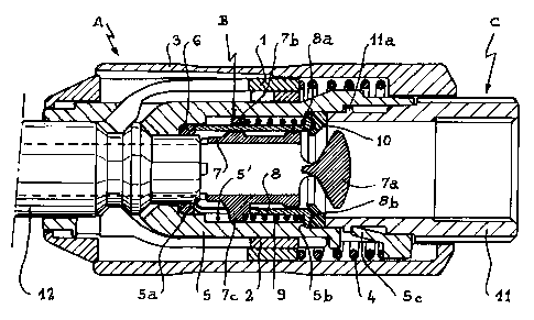
Figure 1 shows the three principal assemblies consti-
tuting the female element of a quick connection according
to the invention, before they are assembled.
Figure 2 is an axial section on a larger scale of
the loaded valve assembly.
Figure 3 is a transverse section along plane III-III
of Figure 2.
Figure 4 is an axial section of the female element
finally produced, with the male element in the fitted
position.

~..
2174470
DESCRIPTION OF PREFERRED EMBODIMENT
It has been assumed that the quick connection in
question was of the type as described in Applicants'
French Patent Application No. 95/00612 filed on January
16, 1995 for "Quick safety connection for removable coup-
ling of pipes", to which reference may be made for more
structural details.
It will simply be recalled that, in this type of
connection, the locking mechanism intended for axially
immobilizing the male element comprises two concentric
sets of clasps 1 and 2 (Figure 1) controlled by a sliding
manoeuvring sleeve 3 associated with a return spring
4.
However, it must be observed that the present inven-
tion is applicable to all types of quick connections
incorporating a loaded valve, whatever the arrangement
of the mechanism intended for locking the male element
inside the female element.
Referring to the drawings, the female element of
the connection according to the invention is formed by
three principal assemblies referenced A, B and C respective-
ly in Figure 1.
Assembly A essentially comprises a tubular piece
5 which is equipped with the locking mechanism 1-2-3-4
mentioned hereinabove. This piece 5, completed by an
inner 0-ring 6 intended to be housed in an annular cavity
5a in its axial bore 5', receives the assembly B which
has been shown in detail in Figures 2 and 3.
As shown, this assembly B comprises a valve constitu-
ted by a sliding sleeve 7 which bears at one of its ends
a suitably profiled obturation head 7a. Near its opposite
end, the sleeve or valve 7 is provided with a ring 7b
which is perforated along its longitudinal axis for assem-
bly and guiding of an outer valve-bearing ring 8, split
longitudinally to leave room for the radial arms 7c defined

2174470
-4-
by the perforations of the sleeve. A spring 9, engaged
on the valve-bearing ring 8 between a shoulder 8a thereof
and the ring 7b of the sleeve 7, tends to push the latter
and to apply its head 7a elastically against a seat for
tightness borne by said ring 8. This seat is constituted
by an 0-ring 10 made of natural or synthetic elastomer.
It will be observed that the seat or 0-ring 10 is
sectioned to comprise, on the one hand, an annular cavity
adapted to centre on a corresponding projection 8b provided
on the terminal face of the ring 8, on the other hand
a projecting lip 10a.
It will be appreciated that the bearing of head
7a against ring 8 limits axial displacement of valve
7 under the effect of spring 9, this latter itself ensuring
hold of said ring in place. Under these conditions, assem-
bly B behaves as a single independent assembly whose
constituent parts cannot be released from one another
in untimely fashion.
This independent assembly B may thus be introduced
axially in the rear opening of bore 5' of the principal
tubular piece 5 of assembly A, in the manner illustrated
in Figure 4. The shoulder 8a abuts against an inner shoul-
der 5b of piece 5, enclosing 0-ring 6 which is thus main-
tained in cavity 5a. It is important to observe that,
due to its projecting nature, the peripheral lip l0a
of ring 10 is wedged in the axial bore of piece 5, so
that assembly B is retained in place by friction inside
assembly A.
This assembly A, provided with assembly B, may thus
be stored as it is in order to be equipped, at the oppor-
tune moment, with assembly C. The latter is in fact consti-
tuted by a tubular piece 11 whose front part is intended
to engage in the rear opening of the bore 5' of the princi-
pal piece 5, while its rear part is sectioned to ensure
fixation thereof to the end of a pipe.

2174470
-5-
Piece 11 may be conventionally fixed in piece 5
by screwing and/or adhesion. However, according to a
particularly advantageous characteristic of the invention,
the inner wall of the axial bore 5' of piece 5 has a
series of longitudinal tongues 5c cut out therein, oriented
obliquely, inwardly and forwardly. Taking into account
this oblique orientation, these tongues 5c are deformed
when piece 11 is axially engaged by force in bore 5'
of piece 5 and return elastically to clip behind an annular
projection lla provided to that end on the periphery
of said piece 11. Any dismantling of the latter is thus
impossible, it being observed that no special tools are
required for assembly which can therefore be effected
very simply when the connections are delivered.
It will be noted that the seat or 0-ring 10 simulta-
neously ensures tightness of the assembly of the two
pieces 5 and 11 which form the body of the female element,
by bearing and gripping between the shoulder 8a and the
terminal edge of the piece 11.
Functioning of valve 7-7a is otherwise identical
to that of conventional valves, in that it is axially
pushed into position of opening when the male element
12 of the connection is fitted in the body 5-11 of the
female element.
It will be appreciated that assembly B may be retained
by friction, no longer by providing a projecting annular
lip 10a, but by giving the periphery of the 0-ring 10
an accentuated deformability adapted to ensure friction
against the wall of the bore 5'.

Representative Drawing
A single figure which represents the drawing illustrating the invention.
Administrative Status

2024-08-01:As part of the Next Generation Patents (NGP) transition, the Canadian Patents Database (CPD) now contains a more detailed Event History, which replicates the Event Log of our new back-office solution.

Please note that "Inactive:" events refers to events no longer in use in our new back-office solution.

For a clearer understanding of the status of the application/patent presented on this page, the site Disclaimer , as well as the definitions for Patent , Event History , Maintenance Fee  and Payment History  should be consulted.

Event History

Description Date
Time Limit for Reversal Expired 2016-04-18
Letter Sent 2015-04-20
Grant by Issuance 2008-02-19
Inactive: Cover page published 2008-02-18
Inactive: Final fee received 2007-12-04
Pre-grant 2007-12-04
Notice of Allowance is Issued 2007-06-29
Letter Sent 2007-06-29
Notice of Allowance is Issued 2007-06-29
Inactive: Approved for allowance (AFA) 2007-06-05
Amendment Received - Voluntary Amendment 2006-12-18
Inactive: S.30(2) Rules - Examiner requisition 2006-06-20
Inactive: IPC from MCD 2006-03-12
Amendment Received - Voluntary Amendment 2003-04-11
Inactive: Application prosecuted on TS as of Log entry date 2003-02-20
Letter Sent 2003-02-20
Inactive: Status info is complete as of Log entry date 2003-02-20
All Requirements for Examination Determined Compliant 2003-01-15
Request for Examination Requirements Determined Compliant 2003-01-15
Application Published (Open to Public Inspection) 1996-10-27

Abandonment History

There is no abandonment history.

Maintenance Fee

The last payment was received on 2007-03-12

Note : If the full payment has not been received on or before the date indicated, a further fee may be required which may be one of the following

  • the reinstatement fee;
  • the late payment fee; or
  • additional fee to reverse deemed expiry.

Please refer to the CIPO Patent Fees web page to see all current fee amounts.

Owners on Record

Note: Records showing the ownership history in alphabetical order.

Current Owners on Record
STAUBLI FAVERGES
Past Owners on Record
CHRISTOPHE LAPORTE
JEAN-JACQUES LACROIX
Past Owners that do not appear in the "Owners on Record" listing will appear in other documentation within the application.
Documents

To view selected files, please enter reCAPTCHA code :


To view images, click a link in the Document Description column. To download the documents, select one or more checkboxes in the first column and then click the "Download Selected in PDF format (Zip Archive)" or the "Download Selected as Single PDF" button.

List of published and non-published patent-specific documents on the CPD .

If you have any difficulty accessing content, you can call the Client Service Centre at 1-866-997-1936 or send them an e-mail at CIPO Client Service Centre.


Document
Description 
Date
(yyyy-mm-dd) 
Number of pages   Size of Image (KB) 
Representative drawing 1999-06-29 1 33
Cover Page 1996-04-18 1 15
Abstract 1996-04-18 1 12
Description 1996-04-18 5 217
Claims 1996-04-18 2 47
Drawings 1996-04-18 3 82
Representative drawing 2006-05-16 1 24
Claims 2006-12-18 1 39
Cover Page 2008-01-29 1 49
Reminder of maintenance fee due 1997-12-22 1 111
Reminder - Request for Examination 2002-12-19 1 113
Acknowledgement of Request for Examination 2003-02-20 1 173
Commissioner's Notice - Application Found Allowable 2007-06-29 1 165
Maintenance Fee Notice 2015-06-01 1 171
Correspondence 2007-12-04 1 29