Sélection de la langue

Search

Sommaire du brevet 2174470 

Énoncé de désistement de responsabilité concernant l'information provenant de tiers

Une partie des informations de ce site Web a été fournie par des sources externes. Le gouvernement du Canada n'assume aucune responsabilité concernant la précision, l'actualité ou la fiabilité des informations fournies par les sources externes. Les utilisateurs qui désirent employer cette information devraient consulter directement la source des informations. Le contenu fourni par les sources externes n'est pas assujetti aux exigences sur les langues officielles, la protection des renseignements personnels et l'accessibilité.

Disponibilité de l'Abrégé et des Revendications

L'apparition de différences dans le texte et l'image des Revendications et de l'Abrégé dépend du moment auquel le document est publié. Les textes des Revendications et de l'Abrégé sont affichés :

  • lorsque la demande peut être examinée par le public;
  • lorsque le brevet est émis (délivrance).
(12) Brevet: (11) CA 2174470
(54) Titre français: AMELIORATIONS APPORTEES AUX RACCORDS RAPIDES
(54) Titre anglais: IMPROVEMENTS IN QUICK CONNECTIONS
Statut: Périmé et au-delà du délai pour l’annulation
Données bibliographiques
(51) Classification internationale des brevets (CIB):
  • F16L 37/46 (2006.01)
  • F16L 37/413 (2006.01)
  • F16L 37/42 (2006.01)
(72) Inventeurs :
  • LACROIX, JEAN-JACQUES (France)
  • LAPORTE, CHRISTOPHE (France)
(73) Titulaires :
  • STAUBLI FAVERGES
(71) Demandeurs :
  • STAUBLI FAVERGES (France)
(74) Agent: MACRAE & CO.
(74) Co-agent:
(45) Délivré: 2008-02-19
(22) Date de dépôt: 1996-04-18
(41) Mise à la disponibilité du public: 1996-10-27
Requête d'examen: 2003-01-15
Licence disponible: S.O.
Cédé au domaine public: S.O.
(25) Langue des documents déposés: Anglais

Traité de coopération en matière de brevets (PCT): Non

(30) Données de priorité de la demande:
Numéro de la demande Pays / territoire Date
95.05240 (France) 1995-04-26

Abrégés

Abrégé français

La présente invention a trait aux raccords rapides qui servent à coupler des tuyaux de façon amovible et qui comprennent un clapet et un joint torique, le clapet, son ressort, une bague fixe et le siège ou joint torique constituant un ensemble monté séparément dans la pièce principale du corps de l'élément négatif. La pièce arrière de ce corps est fixée en place derrière une projection annulaire à l'aide de languettes d'attache élastiques.


Abrégé anglais

This invention relates to quick connections for removably coupling pipes, incorporating a valve and an O-ring, wherein the valve, its spring, a fixed ring and the seat or O-ring constitute an independent assembly which is mounted in the principal piece of the body of the female element. The rear piece of this body is fixed by elastically clipping tongues behind an annular projection.

Revendications

Note : Les revendications sont présentées dans la langue officielle dans laquelle elles ont été soumises.


-6-
WHAT IS CLAIMED IS:
1. Quick connection for removably coupling pipes, of the type in which a
tubular body of
a female element, constituted by a tight assembly of a principal piece and a
rear piece,
contains a valve which is associated with an O-ring forming seat and with a
closure spring
and which is brought into position of opening during fit of a male element in
said female
element, wherein the valve itself, an outer ring which surrounds it, the O-
ring which is borne
by a front end of this ring, and a spring which is maintained between the
valve and said ring,
form an independent assembly which, up to fastening of the rear piece of the
body, is
maintained axially in the axial bore of the principal piece, by friction of
the deformable wall
of the O-ring or seat against the smooth wall of said bore.
2. The connection of Claim 1, wherein the O-ring or seat comprises a
projecting annular
lip.
3. The connection of Claim 1, wherein a terminal face of the outer ring
comprises an
annular projection which cooperates with a corresponding annular cavity made
in the O-ring
to ensure centering thereof on the ring.
4. The connection of Claim 1, wherein the O-Ring ensures, by bearing and
gripping
between an outer shoulder of the ring and a terminal edge of the rear piece,
tight assembly of
the two pieces which form the body of the female element.
5. The connection of Claim 1, wherein the rear piece of the body of the female
element
is fixed in the principal piece by elastic clipping.
6. The connection of Claim 5, wherein an inner wall of the axial bore of the
principal
piece has longitudinal tongues cut out therein, oriented obliquely to be
elastically deformed
and applied against the periphery of the piece behind an annular projection
thereof.

Description

Note : Les descriptions sont présentées dans la langue officielle dans laquelle elles ont été soumises.

2174 4 70
-1-
FIELD OF THE INVENTION
The present invention relates to quick connection
devices used for the dismountable coupling of pipes,
and in particular to those which comprise two male and
female elements fixed at the ends of the pipes to be
connected and adapted to fit one in the other, provoking
automatic opening of a loaded valve provided inside the
female element.
BACKGROUND OF THE INVENTION
In known constructions, the body of the female element
is generally constituted by the tight assembly of two
tubular pieces, ordinarily screwed one in the other,
ensuring at the same time assembly of the valve and of
the closure spring which is associated therewith, which
valve, directly mounted in the core of the body, cooperates
with a seat formed by an 0-ring suitably retained inside
one-of the afore-mentioned pieces.
It will be readily appreciated that such a structure
does not lend itself well to automatic assembly employing
robots or manipulators. Furthermore, it will be recalled
that the shape and dimensions of the rear piece of the
body which is intended to be fastened to the end of a
pipe, vary as a function of the type of coupling envisaged,
which obviously complicates storage of the connections
if it is desired to have a wide range of products available.
It is an object of the present invention to overcome
these dr awb acks .
SUMMARY OF THE INVENTION
The present invention therefore relates to a quick
connection for removably coupling pipes, of the type
in which the tubular body of the female element, constitu-
ted by the tight assembly of a principal piece and
a rear piece, contains a valve which is associated with
an 0-ring forming seat and with a closure spring and
which is brought into position of opening during fit

2174470
-2-
of the male element in said female element, characterized
in that the valve itself, an outer ring which surrounds
it, the 0-ring which is borne by the front end of this
ring, and the spring which is maintained between the
valve and said ring, form an independent assembly which,
up to fastening of the rear piece of the body, is main-
tained axially in the axial bore of the principal piece,
by friction of the deformable wall of the 0-ring or seat
against the smooth wall of said bore.
In other words, the valve, an outer ring which sur-
rounds it, the closure spring which is maintained between
said valve-bearing ring and the valve, and the 0-ring
or seat mounted on the valve-bearing ring, is in the
form of an independent assembly adapted to be introduced
as a whole inside the body of the female element and
to be retained in place therein up to fastening of the
rear-tubular piece of said body, by friction of the defor-
mable periphery of the 0-ring or seat against the smooth
wall of the bore of the body which contains said assembly,
which fastening may be obtained by simple elastic clipping.
BRIEF DESCRIPTION OF THE DRAWINGS
The invention will be more readily understood on
reading the following description with reference to the
accompanying drawings, in which:
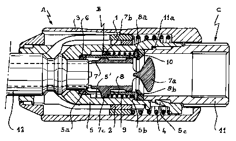
Figure 1 shows the three principal assemblies consti-
tuting the female element of a quick connection according
to the invention, before they are assembled.
Figure 2 is an axial section on a larger scale of
the loaded valve assembly.
Figure 3 is a transverse section along plane III-III
of Figure 2.
Figure 4 is an axial section of the female element
finally produced, with the male element in the fitted
position.

~..
2174470
DESCRIPTION OF PREFERRED EMBODIMENT
It has been assumed that the quick connection in
question was of the type as described in Applicants'
French Patent Application No. 95/00612 filed on January
16, 1995 for "Quick safety connection for removable coup-
ling of pipes", to which reference may be made for more
structural details.
It will simply be recalled that, in this type of
connection, the locking mechanism intended for axially
immobilizing the male element comprises two concentric
sets of clasps 1 and 2 (Figure 1) controlled by a sliding
manoeuvring sleeve 3 associated with a return spring
4.
However, it must be observed that the present inven-
tion is applicable to all types of quick connections
incorporating a loaded valve, whatever the arrangement
of the mechanism intended for locking the male element
inside the female element.
Referring to the drawings, the female element of
the connection according to the invention is formed by
three principal assemblies referenced A, B and C respective-
ly in Figure 1.
Assembly A essentially comprises a tubular piece
5 which is equipped with the locking mechanism 1-2-3-4
mentioned hereinabove. This piece 5, completed by an
inner 0-ring 6 intended to be housed in an annular cavity
5a in its axial bore 5', receives the assembly B which
has been shown in detail in Figures 2 and 3.
As shown, this assembly B comprises a valve constitu-
ted by a sliding sleeve 7 which bears at one of its ends
a suitably profiled obturation head 7a. Near its opposite
end, the sleeve or valve 7 is provided with a ring 7b
which is perforated along its longitudinal axis for assem-
bly and guiding of an outer valve-bearing ring 8, split
longitudinally to leave room for the radial arms 7c defined

2174470
-4-
by the perforations of the sleeve. A spring 9, engaged
on the valve-bearing ring 8 between a shoulder 8a thereof
and the ring 7b of the sleeve 7, tends to push the latter
and to apply its head 7a elastically against a seat for
tightness borne by said ring 8. This seat is constituted
by an 0-ring 10 made of natural or synthetic elastomer.
It will be observed that the seat or 0-ring 10 is
sectioned to comprise, on the one hand, an annular cavity
adapted to centre on a corresponding projection 8b provided
on the terminal face of the ring 8, on the other hand
a projecting lip 10a.
It will be appreciated that the bearing of head
7a against ring 8 limits axial displacement of valve
7 under the effect of spring 9, this latter itself ensuring
hold of said ring in place. Under these conditions, assem-
bly B behaves as a single independent assembly whose
constituent parts cannot be released from one another
in untimely fashion.
This independent assembly B may thus be introduced
axially in the rear opening of bore 5' of the principal
tubular piece 5 of assembly A, in the manner illustrated
in Figure 4. The shoulder 8a abuts against an inner shoul-
der 5b of piece 5, enclosing 0-ring 6 which is thus main-
tained in cavity 5a. It is important to observe that,
due to its projecting nature, the peripheral lip l0a
of ring 10 is wedged in the axial bore of piece 5, so
that assembly B is retained in place by friction inside
assembly A.
This assembly A, provided with assembly B, may thus
be stored as it is in order to be equipped, at the oppor-
tune moment, with assembly C. The latter is in fact consti-
tuted by a tubular piece 11 whose front part is intended
to engage in the rear opening of the bore 5' of the princi-
pal piece 5, while its rear part is sectioned to ensure
fixation thereof to the end of a pipe.

2174470
-5-
Piece 11 may be conventionally fixed in piece 5
by screwing and/or adhesion. However, according to a
particularly advantageous characteristic of the invention,
the inner wall of the axial bore 5' of piece 5 has a
series of longitudinal tongues 5c cut out therein, oriented
obliquely, inwardly and forwardly. Taking into account
this oblique orientation, these tongues 5c are deformed
when piece 11 is axially engaged by force in bore 5'
of piece 5 and return elastically to clip behind an annular
projection lla provided to that end on the periphery
of said piece 11. Any dismantling of the latter is thus
impossible, it being observed that no special tools are
required for assembly which can therefore be effected
very simply when the connections are delivered.
It will be noted that the seat or 0-ring 10 simulta-
neously ensures tightness of the assembly of the two
pieces 5 and 11 which form the body of the female element,
by bearing and gripping between the shoulder 8a and the
terminal edge of the piece 11.
Functioning of valve 7-7a is otherwise identical
to that of conventional valves, in that it is axially
pushed into position of opening when the male element
12 of the connection is fitted in the body 5-11 of the
female element.
It will be appreciated that assembly B may be retained
by friction, no longer by providing a projecting annular
lip 10a, but by giving the periphery of the 0-ring 10
an accentuated deformability adapted to ensure friction
against the wall of the bore 5'.

Dessin représentatif
Une figure unique qui représente un dessin illustrant l'invention.
États administratifs

2024-08-01 : Dans le cadre de la transition vers les Brevets de nouvelle génération (BNG), la base de données sur les brevets canadiens (BDBC) contient désormais un Historique d'événement plus détaillé, qui reproduit le Journal des événements de notre nouvelle solution interne.

Veuillez noter que les événements débutant par « Inactive : » se réfèrent à des événements qui ne sont plus utilisés dans notre nouvelle solution interne.

Pour une meilleure compréhension de l'état de la demande ou brevet qui figure sur cette page, la rubrique Mise en garde , et les descriptions de Brevet , Historique d'événement , Taxes périodiques et Historique des paiements devraient être consultées.

Historique d'événement

Description Date
Le délai pour l'annulation est expiré 2016-04-18
Lettre envoyée 2015-04-20
Accordé par délivrance 2008-02-19
Inactive : Page couverture publiée 2008-02-18
Inactive : Taxe finale reçue 2007-12-04
Préoctroi 2007-12-04
Un avis d'acceptation est envoyé 2007-06-29
Lettre envoyée 2007-06-29
Un avis d'acceptation est envoyé 2007-06-29
Inactive : Approuvée aux fins d'acceptation (AFA) 2007-06-05
Modification reçue - modification volontaire 2006-12-18
Inactive : Dem. de l'examinateur par.30(2) Règles 2006-06-20
Inactive : CIB de MCD 2006-03-12
Modification reçue - modification volontaire 2003-04-11
Inactive : Dem. traitée sur TS dès date d'ent. journal 2003-02-20
Lettre envoyée 2003-02-20
Inactive : Renseign. sur l'état - Complets dès date d'ent. journ. 2003-02-20
Toutes les exigences pour l'examen - jugée conforme 2003-01-15
Exigences pour une requête d'examen - jugée conforme 2003-01-15
Demande publiée (accessible au public) 1996-10-27

Historique d'abandonnement

Il n'y a pas d'historique d'abandonnement

Taxes périodiques

Le dernier paiement a été reçu le 2007-03-12

Avis : Si le paiement en totalité n'a pas été reçu au plus tard à la date indiquée, une taxe supplémentaire peut être imposée, soit une des taxes suivantes :

  • taxe de rétablissement ;
  • taxe pour paiement en souffrance ; ou
  • taxe additionnelle pour le renversement d'une péremption réputée.

Veuillez vous référer à la page web des taxes sur les brevets de l'OPIC pour voir tous les montants actuels des taxes.

Historique des taxes

Type de taxes Anniversaire Échéance Date payée
TM (demande, 2e anniv.) - générale 02 1998-04-20 1998-03-24
TM (demande, 3e anniv.) - générale 03 1999-04-19 1999-03-17
TM (demande, 4e anniv.) - générale 04 2000-04-18 2000-03-23
TM (demande, 5e anniv.) - générale 05 2001-04-18 2001-03-15
TM (demande, 6e anniv.) - générale 06 2002-04-18 2002-03-12
Requête d'examen - générale 2003-01-15
TM (demande, 7e anniv.) - générale 07 2003-04-18 2003-03-10
TM (demande, 8e anniv.) - générale 08 2004-04-19 2004-03-05
TM (demande, 9e anniv.) - générale 09 2005-04-18 2005-03-07
TM (demande, 10e anniv.) - générale 10 2006-04-18 2006-03-08
TM (demande, 11e anniv.) - générale 11 2007-04-18 2007-03-12
Taxe finale - générale 2007-12-04
TM (brevet, 12e anniv.) - générale 2008-04-18 2008-03-11
TM (brevet, 13e anniv.) - générale 2009-04-20 2009-03-20
TM (brevet, 14e anniv.) - générale 2010-04-19 2010-03-16
TM (brevet, 15e anniv.) - générale 2011-04-18 2011-03-21
TM (brevet, 16e anniv.) - générale 2012-04-18 2012-03-23
TM (brevet, 17e anniv.) - générale 2013-04-18 2013-03-21
TM (brevet, 18e anniv.) - générale 2014-04-22 2014-03-14
Titulaires au dossier

Les titulaires actuels et antérieures au dossier sont affichés en ordre alphabétique.

Titulaires actuels au dossier
STAUBLI FAVERGES
Titulaires antérieures au dossier
CHRISTOPHE LAPORTE
JEAN-JACQUES LACROIX
Les propriétaires antérieurs qui ne figurent pas dans la liste des « Propriétaires au dossier » apparaîtront dans d'autres documents au dossier.
Documents

Pour visionner les fichiers sélectionnés, entrer le code reCAPTCHA :


Pour visualiser une image, cliquer sur un lien dans la colonne description du document. Pour télécharger l'image (les images), cliquer l'une ou plusieurs cases à cocher dans la première colonne et ensuite cliquer sur le bouton "Télécharger sélection en format PDF (archive Zip)" ou le bouton "Télécharger sélection (en un fichier PDF fusionné)".

Liste des documents de brevet publiés et non publiés sur la BDBC .

Si vous avez des difficultés à accéder au contenu, veuillez communiquer avec le Centre de services à la clientèle au 1-866-997-1936, ou envoyer un courriel au Centre de service à la clientèle de l'OPIC.


Description du
Document 
Date
(aaaa-mm-jj) 
Nombre de pages   Taille de l'image (Ko) 
Dessin représentatif 1999-06-29 1 33
Page couverture 1996-04-18 1 15
Abrégé 1996-04-18 1 12
Description 1996-04-18 5 217
Revendications 1996-04-18 2 47
Dessins 1996-04-18 3 82
Dessin représentatif 2006-05-16 1 24
Revendications 2006-12-18 1 39
Page couverture 2008-01-29 1 49
Rappel de taxe de maintien due 1997-12-22 1 111
Rappel - requête d'examen 2002-12-19 1 113
Accusé de réception de la requête d'examen 2003-02-20 1 173
Avis du commissaire - Demande jugée acceptable 2007-06-29 1 165
Avis concernant la taxe de maintien 2015-06-01 1 171
Correspondance 2007-12-04 1 29