Note: Descriptions are shown in the official language in which they were submitted.
~~.74691
Back;~round of the Invention
The present invention relates to a filter condition sensor and indicator, and
more
particularly, to a filter condition sensor and indicator that responds to the
presence of a
predetermined collection of material in a filter that is operatively
positioned in an output air
flow path which may include a mufti-speed fan.
In a product such as a humidifier, vacuum cleaner or other product containing
a filter,
it is desirable to know when the filter is clogged since this can adversely
affect performance.
Typically, a clogged filter is one where the air pressure drop across the
filter increases.
The prior art has suggested various ways in which a clogged filter can be
indicated to a
user. U.S. Patent No. 4,050,291 discloses heated thermistors used in a bridge
circuit with a
filter sensor and indicator device; U.S. Patent No. 4,040,042 teaches the use
of a current
sensing resistor in a blower energizing circuit; and U.S. Patent No. 4,240,072
discloses an
energy sensor in the form of a closed loop flux conducting circuit. All of
these prior art
techniques have proved to be useful for certain applications.
Sensing the condition of a filter and providing a visual indication of the
filter to the
user becomes more complicated when a mufti-speed fan is used in a product such
as those
identified above. When the fan speed in changed, the velocity of air through
the filter is also
changed, and this may cause the indicator to "trip" when the filter is not
clogged or fail to
indicate a clogged filter.
The present invention has been constructed specifically to overcome the
aforementioned problems in a new and improved construction not previously
taught or
suggested by the prior art.
MK/SPD 5908.APP 2
X174691
Summar~r of the Invention
Among the several objects and advantages of the present invention include:
A new and improved filter condition sensor and indicator for a product such as
a
humidifier, vacuum cleaner or other similar product containing a filter;
The provision of the aforementioned filter condition sensor and indicator
which is
separate from an output air flow path containing the filter;
The provision of the aforementioned filter condition sensor and indicator in
which a
small by-pass air flow path contains a heated thermistor which illuminates
when resistance in
an electrical circuit containing the thermistor and indicator light decreases;
The provision of the aforementioned filter condition sensor and indicator in
which the
thermistor is electrically coupled to means for changing the voltage and
current through the
thermistor where a mufti-speed fan is located in the output air flow path;
The provision of the aforementioned filter condition sensor and indicator
which is
simple, durable, economical, requires low maintenance and is otherwise well
adapted for the
purposes intended.
Briefly stated, the filter condition sensor and indicator of the present
invention
responds to the presence of a predetermined collection of material in a filter
that is operatively
positioned in an output air flow path. A small by-pass air flow path is
connected to the output
air flow path and is separate from the filter. A heated thermistor is placed
in the by-pass air
flow path. Electrically connected in series in a circuit with the heated
thermistor is an
indicator light that illuminates when the resistance in the circuit is
decreased due to
predetermined cooling of the heated thermistor. Thus, a predetermined
collection of material
MK/SPD 5908.APP
'' X1'74691
in the filter increases the flow of air in the small by-pass air flow path for
cooling the heated
thermistor and lowering resistance in the circuit to illuminate the indicator
light.
The heated thermistor may be connected in series with the resistor whose
resistance is
lowered when the air flow in the by-pass air flow path is increased. The
thermistor is
preferably a positive temperature coefficient thermistor for air flow
sensitivity that permits
rapid change of resistance.
The small by-pass air flow path may extend through the filter or outside the
filter,
depending upon the construction that is preferred.
Where a multi-speed fan is located in the output airflow path, the thermistor
is
electrically coupled to means for changing the voltage and current through the
thermistor
depending on the fan setting. The last mentioned means may comprise tapped
coils of a
mufti-speed motor that operates the mufti-speed fan. The last mentioned means
may also
comprise a switch that changes the resistance in the thermistor as the fan
speed is changed.
These and other objects and advantages will become apparent from the
description that
follows.
Brief Description of the Drawings
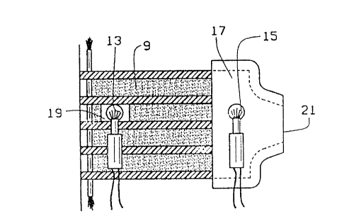
In the drawings, Figure 1 is a fragmentary perspective view of an upper area
of a
humidifier showing a mufti-speed fan and an output air flow path containing a
filter;
Figure 2 is a fragmentary side elevational view, partially in section, of
various ways in
which a heated thermistor can be used in a separate by-pass air flow path
according to the
present invention;
MKJSPD 5908.APP
'' X174691
Figure 3 is a schematic view of a typical electric circuit used in connection
with a filter
condition sensor and indicator of the present invention; and
Figure 4 is a graphic illustration charting resistance and temperature in
connection
with dirty and clean air flow through a filter.
Corresponding reference numerals will be used throughout the several figures
of the
drawings.
Description of the Preferred Embodiments
The following detailed description illustrates the invention by way of example
and not
by way limitation. This description will clearly enable one skilled in the art
to make and use
the invention, and describes several embodiments, adaptions, variations,
alternatives and uses
of the invention, including what I presently believe is the best mode of
carrying out the
invention.
While the filter condition sensor and indicator of the present invention can
be used in a
variety of different products such as a humidifier, vacuum cleaner or any
other product
containing a filter, Figure 1 of the drawings disclose the present invention
in connection with
a humidifier. At the upper end of the humidifier 1 is a compartment 3 that
contains a motor
driven mufti-speed fan blade 5 that is positioned in an output air flow path 7
for drawing air
through the humidifier, as is well known. At one side of the humidifier 1 is a
filter 9 which
typically is associated with an air inlet (not shown) for trapping foreign
particles and other
debris that are drawn into the humidifier 1 by the motor driven mufti-speed
fan blade 5. A
molded screen (not shown) is typically mounted on top of the humidifier 1, to
cover one or
more of the compartments and the mufti-speed fan blade 5.
MK/SPD 5908.APP
CA 02174691 1999-11-02
As indicated above, it is important to sense the condition of the filter 9 in
order to
provide a visual indication to a user when the filter becomes clogged. As will
be appreciated,
a clogged filter can adversely affect performance of a product, such as the
humidifier 1. This
problem becomes more complicated when a mufti-speed fan is used, as in the
motor driven
mufti-speed fan blade 5 shown in Figure 1. When the speed of the fan blade 5
is changed, the
velocity of the air through the filter will also be changed, and this may
cause any filter
condition sensor and indicator to "trip" when the filter is not clogged or
fail to indicate a
clogged filter.
To overcome these problems, the present invention discloses a new and improved
filter
condition sensor and indicator which responds to the presence of a
predetermined collection
of material in the filter that may be operatively positioned in an output air
flow path which
may include a mufti-speed fan, such as the environment illustrated in Figure 1
of the
drawings.
Adjacent the compartment 3 in the humidifier 1 is a compartment 11 which may
contain
various electrical conduit shown in dotted lines, as well as a heated
thermistor 13 which is
used in connection with the filter 9. Alternatively, a thermistor 15 may be
provided in a
compartment 17, adjacent one side of the compartment 3, if desired.
This is best illustrated in Figure 2 of the drawings where a thermistor 13 is
both shown
as used in connection with the filter 9 as well as the alternative arrangement
of a thermistor 15
which may be used in the separate compartment 17. Whichever construction is
used, it is
important that a small by-pass air flow path be connected to the output air
flow path 7 separate
from the filter 9. As shown in Figure 2 of the drawings, the heated thermistor
13 is placed in
~m4sm
a separate by-pass air flow path 19 which extends through but allows air to
flow around the
filter 9. The separate by-pass air flow path 19 is connected through the
various compartments
at the upper end of the humidifier 1 to the output air flow path 7.
Alternatively, the heated
thermistor 15 may be placed in the separate compartment 17 constituting a
small by-pass air
flow path which is also connected to the output air flow path 7 separate from
the filter 9. In
the case of the separate compartment small by-pass air flow path 17, an air
outlet 21 is
necessary in order to allow air passing through the small by-pass air flow
path 17 to be
discharged out the air outlet 21.
As shown in the graphic illustration in Figure 4 of the drawings, as the air
velocity
increases in the small by-pass air flow path 17 or 19, due to clogging in the
filter 9, the
thermistor 13 or 15 will be cooled more and its resistance decreases. By using
a positive
temperature coefficient thermistor (PTC) for the thermistors 13 or 15 and by
coupling same in
series with a resistor, the increased air velocity in the small by-pass air
flow path 17 or 19 can
be made more precipitous such that at a low air flow, the resistance in the
thermistor 13 or 15
is very high and at a certain increased air flow, the heated thermistors 13 or
15 can be
switched to a much lower resistance. This large change of resistance can be
used to light an
indicator across either of the thermistors 13 or 15 on a resistor in series
with either of the
thermistors 13 or 15.
Figure 3 of the drawings shows a typical electrical circuit 23 used in
connection with
the filter condition sensor and indicator of the present invention. At the
left hand side of the
circuit 23, a mufti-position switch 25 is shown as operating between low,
medium or high
positions in controlling the motor driven mufti-speed fan blade 5. The
thermistor 13
MK/SPD 5908.APP 7
~''' ~174~g~
illustrated in Figure 3 (which could be the thermistor 15 as well) is
electrically coupled to the
tapped coils 27 of a mufti-speed motor (not shown) that operates the motor
driven mufti-speed
fan blade S. A resistor 29 extends across the circuit 23 in conjunction with
the indicator light
31. A separate ion generator 33 may also be coupled to an ion light 35 through
a manual
switch 37 in the electrical circuit 23, if desired. Also, a power light 39 may
be used to
indicate power in the system.
By coupling the thermistor 13 with the tapped coils 27 of a mufti-speed motor
(not
shown), the voltage and current through the thermistor can be changed,
depending on the fan
setting. The tapped coils 27 of the mufti-speed motor (not shown) are
effectively used as an
auto-transformer to change the voltage applied to (and the current through)
the thermistor 13
and the series resistor 29, depending on the fan setting. Thus, at high fan
speed, the voltage
across the thermistor 13 and the series resistor 29 is increased such that a
higher air velocity in
one or the other of the small by-pass air flow paths 17, 19 is required to
indicate a clogged
filter. In this way, the effects of the motor driven mufti-speed fan blade 5
may be
compensated.
The thermistor indicator light 31 is electrically connected in series with the
heated
thermistor 13 for illumination when the resistance in the circuit 23 is
decreased due to a
predetermined cooling of the heated thermistor. As a result, a predetermined
collection of
material in the filter 9 increases the flow of air in the small by-pass air
flow path 17 or 19, in
order to cool the heated thermistor 13 or 15 for lowering the resistance in
the circuit, such as
through the resistor 29, in order to illuminate the indicator light 31.
Preferably, the thermistor
MK/SPD 5908.APP
'" 2:l'~469I
13 or 15 is a positive temperature coefficient thermistor (PTC) for air flow
sensitivity that
permits rapid change of resistance.
In lieu of using the tapped coils 27 of a mufti-speed motor (not shown) to
change the
voltage and current through the thermistor 13 when a motor driven mufti-speed
fan blade 5 is
used, a switch that changes the resistance in the thermistor as the fan speed
is changed, may
also be used. In either instance, the voltage and current through the
thermistor will be
changed, depending on the fan setting.
From the foregoing, it will now be appreciated that the filter condition
sensor and
indicator of the present invention discloses a new and improved construction
that senses the
condition of a filter and provides a visual indication of the filter to a
user, such as through an
indicator light, even when a mufti-speed fan is used in a product such as a
humidifier, vacuum
cleaner or other such appliance. Even when the fan speed is changed, the
velocity of air
through the filter will also be changed, and this will not cause the sensor to
"trip" when the
filter is not clogged or fail to indicate a clogged filter.
In view of the above, it will be seen that the several objects and advantages
of the
present invention have been achieved and other advantageous results have been
obtained.
As various changes could be made in the above constructions without departing
from
the scope of the invention, it is intended that all matter contained in the
above description or
shown in the accompanying drawings shall be interpreted as illustrative and
not in a limiting
sense.
MK/SPD 5908.APP