Note: Descriptions are shown in the official language in which they were submitted.
WO 95/13108 - PCT/US94112870
1
METHOD AND DEVICE FOR ASSISTING
CARDIOPULMONARY RESUSCITATION
BACKGROUND OF THE INVENTION
1. Field of the Invention
The present invention relates generally to devices
and methods used in conjunction with external chest compression
and decompression as a part of cardiopulmonary resuscitation
procedures. In particular, the present invention relates to
devices and methods for increasing cardiopulmonary circulation
induced by chest compression and decompression when performing
cardiopulmonary resuscitation.
Worldwide, sudden cardiac arrest is a major cause of
death and is the result of a variety of circumstances,
including heart disease and significant trauma. In the event
of a cardiac arrest, several measures have been deemed to be
essential in order to improve a patient's chance of survival.
These measures must be taken as soon as possible to at least
partially restore the patient's respiration and blood
circulation. One common technique, developed approximately 30
years ago, is an external chest compression technique generally
referred to as cardiopulmonary resuscitation (CPR). CPR
techniques have remained largely unchanged over the past two
decades.
With traditional CPR, pressure is applied to a
patient's chest in order to increase intrathoracic pressure.
An increase in intrathoracic pressure induces blood movement
from the region of the heart and lungs towards the peripheral
arteries. Such pressure partially restores the patient's
circulation. Traditional CPR is performed by actively
compressing the chest by direct application of an external
pressure to the chest. After active compression, the chest is
allowed to expand by its natural elasticity which causes
expansion of the patient's chest wall. This expansion allows
some blood to enter the cardiac chambers of the heart. The
procedure as described, however, is insufficient to ventilate
WO 95!13108 217 4 7 l 8 PCT/US94/12870
2
the patient. Consequently, conventional CPR also requires
periodic ventilation of the patient. This is commonly
accomplished by mouth-to-mouth technique or by using positive-
pressure devices, such as a self-inflating bag which relies on ,
squeezing an elastic bag to deliver air via a mask,
endotracheal tube or other artificial airway.
In order to increase cardiopulmonary circulation
induced by chest compression, a technique referred to as active
compression-decompression (ACD) has been developed. According
to ACD techniques, the active compression phase of traditional
CPR is enhanced by pressing an applicator body against the
patient's chest to compress the chest. Such an applicator body
is able to distribute and apply force substantially evenly over
a portion of the patient's chest. More importantly, however,
the applicator body is sealed against the patient's chest so
that it may be lifted to actively expand the patient's chest
during the decompression step. The resultant negative
intrathoracic pressure induces venous blood to flow into the
heart and lungs from the peripheral venous vasculature of the
patient.
Also of importance to the invention are ventilation
sources that are used in connection with CPR techniques to
properly ventilate the patient. One type of ventilation source
is the AMBU bag available from AMBU International, Copenhagen,
Denmark. The AMBU bag can also be used in connection with a
positive end-expiratory pressure (PEEP) valve, available from
AMBU International, to treat some patients with pulmonary and
cardiac diseases. However, until the present invention, a
positive end-expiratory pressure valve in connection with a
ventilation source has not been used with any CPR techniques.
With both traditional CPR and ACD-CPR techniques, an
increase in the amount of venous blood flowing into the heart
and lungs from the peripheral venous vasculature would be
desirable to increase the volume of oxygenated blood leaving
the thorax during the subsequent compression phase. It would
therefore be desirable to provide improved methods and
apparatus for enhancing venous blood flow into the heart and
lungs of a patient from the peripheral venous vasculature
CA 02174778 2004-11-09
64157-476
3
during both conventional CPR and ACD-CPR techniques. It would
be particularly desirable to provide techniques which would
enhance oxygenation and increase the total blood return to the
chest during the decompression step of CPR and ACD-CPR, more
particularly of ACD-CPR. This can be accomplished according to
the present invention by augmentation of both negative and
positive intrathoracic pressure, thereby amplifying the total
intrathoracic pressure swing. An invention for providing this
crucial improvement is described.
2. Description of the Background Art
ACD-CPR techniques are described in detail in Todd J.
Cohen et al., Active Compression-Decompression Resuscitation:
A Novel Method of Cardiopulmonary Resuscitation, American Heart
Journal, Vol. 124, No. 5, pp. 1145-1150, November 1992; Todd J.
Cohen et al., Active Compression-Decompression: A New Method
of Cardiopulmonary Resuscitation, The Journal of the American
Medical Association, Vol. 267, No. 21, June 3, 1992; and J.
Schultz, P. Coffeen, et al., Circulation, in press, 1994.
The use of a vacuum-type cup for actively compressing
and decompressing a patient's chest during ACD-CPR is described
in a brochure of AMBU International A/S, Copenhagen, Denmark,
entitled Directions for Use of AMBU~ CardioPumpn', published in
September 1992. The AMBU~ CardioPump'"' is also disclosed in
European Patent Application No. 0 509 773 A1.
SUMMARY OF THE INVENTION
According to the invention, methods and devices for
increasing cardiopulmonary circulation induced by chest
compression and decompression when performing cardiopulmonary
resuscitation are provided. The methods and devices may be
used in connection with any generally accepted CPR methods or
with active compression-decompression (ACD) CPR techniques.
Preferably, the methods and devices will be used in connection
with ACD-CPR.
WO 95/13108 , ~ , PCT/US94/12870
4
Cardiopulmonary circulation is increased according to
the invention by impeding air flow into a patient's lungs
during the decompression phase. This increases the magnitude
and prolongs the duration of negative intrathoracic pressure
during decompression of the patient's chest, i.e., increases
the duration and degree that the intrathoracic pressure is
below or negative with respect to the pressure in the
peripheral venous vasculature. By enhancing the amount of
venous blood flow into the heart and lungs, since equilibration
to of intrathoracic pressure during decompression occurs to a
greater extend from enhanced venous return rather than rapid
inflow of gases into the chest via the patient°s airway,
cardiopulmonary circulation is increased.
In a specific embodiment, impeding the air flow into
the patient's lungs is accomplished by decreasing or preventing
ventilation during the decompression phase of CPR. The method
employs the use of a flow restrictive or limiting member, such
as a flow restrictive orifice disposed within or connected in
series with a lumen of a ventilation tube, or a pressure-
responsive valve within a lumen of the tube to impede the
inflow of air. The pressure-responsive valve is biased to open
to permit the inflow of air when the intrathoracic pressure
falls below a threshold level. In order to properly ventilate
the patient, the method preferably provides for periodically
ventilating the patient through the ventilation tube after
compression of the patient's chest. When periodic ventilation
is performed, gases can be delivered either through the
impeding step or in another embodiment they can bypass the
impeding step.
. An exemplary embodiment provides for covering the
patient's mouth and nose with a facial mask. This mask
contains means for impeding air flow into the patient's airway
during decompression of the patient's chest, e.g. either an
orifice or valve as just discussed.
A specific embodiment further provides means for
impeding air from leaving the lungs during compression of the
patient°s chest to further enhance cardiopulmonary circulation
CA 02174778 2005-09-O1
64157-476
by enhancing positive intrathoracic pressure during the
compression phase.
When performing cardiopulmonary resuscitation to
enhance circulation according to the invention, an operator
5 compresses a patient's chest to force blood out of the
patient's thorax. The patient's chest is then decompressed to
induce venous blood to flow into the heart and lungs from the
peripheral venous vasculature either by actively lifting the
chest (via ACD-CPR) or by permitting the chest to expand due to
its own elasticity (via conventional CPR). During the
decompression step, air flow is impeded from entering into the
patient's lungs which enhances negative intrathoracic pressure
and increases the time during which the thorax is at a lower
pressure than the peripheral venous vasculature. Thus, venous
blood flow into the heart and lungs from the peripheral venous
vasculature is enhanced. This is because the intrathoracic
pressure equilibrium during decompression occurs as a result of
enhanced venous return rather than from inflow of air via the
trachea. In a particular embodiment, compression and
decompression of the patient's chest may be accomplished by
pressing an applicator body against the patient's chest to
compress the chest, and lifting the applicator to actively
expand the patient's chest.
An apparatus for enhancing cardiopulmonary
circulation according to the method comprises an improved
endotracheal tube having a flow restrictive element for
impeding air flow from the patient's lungs during chest
decompression. A second apparatus according to the invention
provides for an improved air-delivery system comprising a
compressible structure having a flow restrictive element
included in or attached to an opening of the compressible
structure to impede the flow of gases to the patient's lungs.
Also, a connector is provided for interfacing the compressible
structure to the patient, preferably by attaching a facial mask
or endotracheal tube to the structure.
CA 02174778 2005-09-O1
64157-476
5a
The invention may be summarized according to one
aspect as an improved system for delivering a preselected
volume of air of the type in which a compressible structure
having a first opening and a second opening, a one-way
valve for the intake of air included in or attached to the
first opening, and means located at the second opening for
delivering a preselected volume of air, wherein the
improvement is for delivering air flow to a patient's lungs
when a minimum intrathoracic pressure is exceeded
comprising: means for interfacing in a permanent or
detachable manner said compressible structure to the
patient; and means included in or attached to the second
opening of the compressible structure to impede the flow of
gases to the patient's lungs until the minimum
intrathoracic pressure is exceeded, whereby a rise in
intrathoracic pressure is slowed during decompression of
the patient's chest and the extent and duration of negative
intrathoracic pressure is enhanced in order to enhance
venous blood flow into the heart and lungs from the
peripheral venous vasculature when performing
cardiopulmonary resuscitation.
According to another aspect the invention
provides an apparatus for use during cardiopulmonary
resuscitation of a patient, the apparatus having a
structure for ventilating the patient with a first opening
for allowing ingress of air; means located at a second
opening of the structure for permitting air to leave the
structure; means for conducting air to the airway of the
patient; the apparatus characterised by further having
means included in or attached to the second opening to
impede the flow of gases to the patient until a minimum
pressure difference across the impeding means is exceeded,
whereby when performing cardiopulmonary resuscitation the
CA 02174778 2005-09-O1
64157-476
5b
extent and the duration of negative intrathoracic pressure
during decompression of the patient's chest is enhanced in
order to enhance venous blood flow into the heart and lungs
from the peripheral venous vasculature.
According to another aspect the invention
provides an apparatus for use when ventilating a patient,
the apparatus comprising: a first opening for allowing
ingress of air and means located at a second opening of the
structure for permitting air to leave the structure; means
for conducting air to the airway of the patient; and means
included in or attached to the second opening to impede the
flow of gases to the patient until a minimum pressure
difference across the impeding means is exceeded; whereby
the extent and the duration of negative intrathoracic
pressure is enhanced in order to enhance venous blood flow
into the heart and lungs from the peripheral venous
vasculature.
According to another aspect the invention
provides an improved system for delivering a volume of
respiratory gases of the type in which a compressible
structure having a first opening and a second opening, a
one-way valve for the intake of gases included in or
attached to the first opening, and means located at the
second opening for delivering a volume of respiratory
gases, wherein the improvement comprises: means for
interfacing in a permanent or detachable manner said
compressible structure to the patient; and a
pressure-responsive valve included in or attached to the
second opening of the compressible structure to prevent the
flow of all respiratory gases to the patient's lungs until
the intrathoracic pressure generated by chest compression
and decompression on a non-breathing patient falls below a
threshold level whereupon said intrathoracic pressure
CA 02174778 2005-09-O1
64157-476
5c
causes the valve to open to allow gases to flow passively
through said valve to the lungs due to a pressure
differential between the atmosphere and said negative
intrathoracic pressure in the patient's chest, said valve
when closed slows a rise in intrathoracic pressure during
decompression of the patient's chest and to enhance the
extent and duration of negative intrathoracic pressure in
order to enhance venous blood flow into the heart and lungs
from the peripheral venous vasculature when performing
cardiopulmonary resuscitation.
A further understanding of the nature and
advantages of the invention will become apparent by
reference to the remaining portions of the specification
and drawings.
WO 95!13108 -~ PCT/US94/128?0
6
BRIEF DESCRIPTION OF THE DRAWINGS
Fig. 1 is a graph illustrating thoracic pressure
changes over time when compressing and decompressing a
patient's chest according to the present invention.
Fig. 2A is a schematic view illustrating air flow
through a ventilation circuit when compressing a patient's
chest according to the present invention.
Fig. 2B is a schematic view illustrating air flow
through a ventilation circuit when decompressing a patient's
chest according to the present invention.
Fig. 3 is a schematic illustration of a first
alternative embodiment of a device for impeding air flow into a
patient's lungs according to the present invention.
Fig. 4A is a schematic illustration of a second
alternative embodiment of the device for impeding air flow into
a patient's lungs according to the present invention.
Fig. 4B is a schematic illustration of the device in
Fig. 4A with a common inhalation/exhalation port.
Fig. 5A is a schematic view of a one-way valve used
in the device for impeding air flow according to the present
invention.
Fig. 5B is a schematic view of the one-way valve in
Fig. 5A that is held open after ACD-CPR has ceased.
Fig. 5C is a schematic view of a one-way valve that
is closed until a threshold pressure is present in the tube
according to the present invention.
Fig. 6A is a schematic view of a spring biased inflow
valve and a spring biased expiration valve to be used in
accordance with the present invention.
Fig. 6B is a schematic view of Fig. 6A showing the
operation of the valves during outflow of air.
Fig. 6C is a schematic view of Fig. 6A showing the
operation of the valves during inflow of air.
Fig. 7 is a schematic view of a single valve that is
spring biased from both sides to be used as an inflow valve and
an expiration valve according to the present invention.
WO 95!13108 a a PCTlUS94/12870
7
Fig. 8 is a schematic view of a flow restricting
orifice to be used with a flow restrictive device according to
the present invention.
Fig. 9 is a schematic view of an exemplary embodiment
of the device for impeding air flow into a patient's lungs
according to the present invention.
Figs. l0A-10C are schematic views illustrating
another embodiment of the present invention allowing for
periodic patient ventilation through a bypassing valve.
DETAINED DESCRIPTION OF SPECIFIC EMBODIMENTS
According to the present invention, methods and
devices for increasing cardiopulmonary circulation induced by
chest compression and decompression when performing
cardiopulmonary resuscitation are provided. Such methods and
devices may be used in connection with any method of CPR in
which intrathoracic pressures are intentionally manipulated to
improve cardiopulmonary circulation. For instance, the present
invention would improve standard manual CPR, "vest'° CPR, CPR
with a newly described Hiack Oscillator ventilatory system
which operates essentially like an iron-lung-like device,
interposed abdominal compression-decompression CPR, and active
compression-decompression (ACD) CPR techniques. Although the
present invention may improve all such techniques, the
following description will refer primarily to improvements of
ACD-CPR techniques in order to simplify discussiox~. However,
the claimed methods and devices are not exclusively limited to
ACD-CPR techniques.
The proper performance of ACD-CPR to increase
cardiopulmonary circulation is accomplished by actively
compressing a patient's chest with an applicator body.
Preferably, this applicator body will be a suction-type device
that will adhere to the patient's chest, such as the AMBU~
CardioPump"', available from AMBU International, Copenhagen,
Denmark. After the compression step, the adherence of the
applicator body to the patient's chest allows the patient's
chest to be lifted to actively decompress the patient's chest.
The result of such active compression-decompression is to
CA 02174778 2004-11-09
64157-476
8
increase intrathoracic pressure during the compression step,
and to increase the negative intrathoracic pressure during the
decompression step thus enhancing the blood-oxygenation process
and enhancing cardiopulmonary circulation. ACD-CPR techniques
are described in detail in Todd J. Cohen et al., Active
Compression-Decompression Resuscitation: A Novel Method of
Cardiopulmonary Resuscitation, American Heart Journal,
Vol. 124, No. 5, pp. 1145-1150, November 1992; Todd J. Cohen et
al., Active Compression-Decompression: A New Method of
Cardiopulmonary Resuscitation, The Journal of the American
Medical Association, Vol. 267, No. 21, June 3, 1992; and J.
Schultz, P. Coffeen, et al., Circulation, in press, 1994.
The present invention is especially useful in
connection with ACD-CPR techniques. In particular, the
invention improves ACD-CPR by providing methods and devices
which impede air flow into a patient's lungs to enhance
negative intrathoracic pressure during the decompression of the
patient's chest, thus increasing the degree and duration of a
pressure differential between the thorax (including the heart
and lungs) and the peripheral venous vasculature. Enhancing
negative intrathoracic pressure with simultaneous impedance of
movement of gases into the airway thus enhances venous blood
flow into the heart and lungs and increases cardiopulmonary
circulation.
In a broad sense, the present invention provides for
occluding a patient's airway to prevent foreign (outside) air
from flowing to a patient's lungs during the active
decompression step of ACD-CPR to enhance and sustain the
duration of negative intrathoracic pressure and enhance blood
oxygenation and cardiopulmonary circulation during both active
decompression and the subsequent compression phase. The
patient's airway may be occluded or inflow of gases impeded by
any suitable device or mechanism such as by an endotracheal
tube, a device attached to an endotracheal tube, a facial mask,
a mouth piece used in mouth-to-mouth resuscitation,
oropharyngeal airway, laryngeal mask airway, and the like:
WO 95/13108 a
PCT/US94/12870
9
A further aspect of the present invention provides
for allowing impeded air to flow into the patient's lungs
during the active decompression step of ACD-CPR in order to
provide some ventilation to the patient while still enhancing
the extent and duration of negative intrathoracic pressure to
enhance blood oxygenation. Impeding air flow to the patient's
lungs may be accomplished by any flow restrictive element such
as an orifice, a spring biased or other valve which is set to
open when the negative intrathoracic pressure is in the range
from about 0 cm H20 to -100 cm H20, a one-way valve, or the
like. A valve designed to open at a threshold pressure value
may be either fixed or variable, i.e., the pressure at which
the valve opens may be adjusted or may be permanently fixed.
Similarly, another aspect of the invention provides
for air to be impeded from leaving the patient's lungs during
compression of the patient's chest to further enhance
cardiopulmonary circulation by enhancing intrathoracic pressure
during the compression phase. Typically, air is impeded from
leaving the lungs during the compression phase when the
positive intrathoracic pressure is in the range from about 5 cm
H20 to 50 cm H20.
Another aspect of the present invention provides for
ventilating the patient during ACD-CPR. Ventilation of the
patient is performed at about every two to 10 compressions,
preferably every five compressions, thus providing sufficient
fresh air for adequate gas exchange with the blood in the lungs
to the patient. Ventilating the patient may be accomplished
by any device or method suitable such as by mouth-to-mouth
resuscitation, by a compressible or collapsible structure, by a
ventilatory bag such as the AMBU bag available from AMBU,
Copenhagen, Denmark, or the like. Ventilation could also be
superimposed on the compression phase to further augment
positive intrathoracic pressure. Furthermore, periodic
ventilation could be performed. either through the impeding step
or by bypassing the impeding step altogether.
Referring now to Fig. 1, a graph illustrating
thoracic pressure changes over time when compressing and
decompressing the patient's chest is shown. Area 10 represents
CA 02174778 2004-11-09
64157-476
the amount of thoracic pressure during the compression phase of
ACD-CPR. Cross-hatched area 12 represents the negative
thoracic pressure during the decompression step of ACD-CPR
without a flow restrictive means to restrict the flow of air
5 into the patient's lungs. Double cross-hatched area 14
represents the increase in negative thoracic pressure when the
patient's airway is occluded according to the present invention
during the decompression step of ACD-CPR. The significance of
the increase in negative intrathoracic pressure during the
10 decompression step is that more venous blood is forced into the
chest from the peripheral venous vasculature. Consequently,
more blood is allowed to be oxygenated and more blood is forced
out of the chest during the next compression.
In an exemplary embodiment, air flow may be impeded
i5 to the patient's lungs during decompression of the patient's
chest by placing a ventilatory mask over the patient's mouth
and nose. The ventilatory mask also has a pressure-responsive
valve attached to prevent air flow to the patient's lungs until
the negative intrathoracic pressure of the patient reaches a
threshold amount. Also attached to the mask and the pressure-
responsive valve is a ventilatory source to provide ventilation
to the patient. The ventilatory source may be any device or
apparatus suitable for properly ventilating the patient.
Preferably, the ventilation source will be an AMBU bag. When
ventilation is needed, the AMBU bag may be squeezed to force
air into the patient's lungs. The AMBU bag is described in
U.S. Patent No. 5,163,424.
In an alternative embodiment, a ventilation source,
preferably an AMBU bag, is used in connection with an improved
endotracheal tube. A pressure-responsive valve or other flow
restrictive element is placed between the AMBU bag and the
endotracheal tube. Preferably, the valve will be positioned
within a tube that connects the AMBU bag to the endotracheal
tube. The combination of the endotracheal tube with the AMBU
bag with adapter can be included in the definition of a
"ventilation tube." Before ACD-CPR is performed on the
patient, the endotracheal tube is placed in the patient's
WO 95/13108 PCT/US94/12870
11
trachea. During decompression of the patient's chest, the
valve prevents air flow to the patient's lungs until the
intrathoracic pressure reaches a threshold amount.
Additionally, the AMBU bag may be used to ventilate the patient
at a desired time. Also included in this embodiment is a one-
way expiration valve. This valve allows for expiration of air
from the patient during the compression step.
In a modification of either of the f first two
embodiments, an pressure-responsive expiration valve may also
be inserted between the AMBU bag (or comparable ventilation
source) and the mask or endotracheal tube. This valve works in
a similar manner to the pressure-responsive valve which
restricts air flow into the patient's lungs. However, the
pressure-responsive expiration valve restricts air flow from
the patient's lungs during the compression step of ACD-CPR. An
equivalent valve is a positive end-expiratory pressure (PEEP)
valve available from AMBU International, Copenhagen, Denmark.
Use of such an pressure-responsive expiration valve during
compression may further increase intrathoracic pressure and
thereby force more blood out of the thorax.
In another alternative embodiment, an improved
endotracheal tube is used to restrict air flow into the
patient's lungs during the active decompression step. Included
in the endotracheal tube is a flow restrictive element which
operates to impede air from flowing into the patient's lungs.
When the endotracheal tube is inserted into the patient°s
trachea and the patient's chest is actively decompressed, the
flow restrictive element impedes air from flowing to the
patient's lungs slowing the rise in intrathoracic pressure and
thus enhancing blood oxygenation.
When using the improved endotracheal tube during ACD-
CPR, periodic ventilation of the patient will usually still be
performed to enhance gas exchange to the patient. With the
improved endotracheal tube, such manual ventilation may be
accomplished by placing a ventilation source at the opening of
the endotracheal tube to force oxygen through the endotracheal
tube and into the patient's lungs.
WO 95113108 PCT/IJS94/12870
12
Referring now to Fig. 2A, a schematic view
illustrating air flow through a ventilation circuit 20 when
compressing a patient's chest according to the present
invention is shown. During ACD-CPR, the chest is actively
compressed forcing air out of the lungs. This air is allowed
to expire through a one-way expiration valve 22 within a
ventilation circuit 20.
Referring now to Fig. 2B, the same schematic is shown
illustrating air flow through the ventilation circuit 20 when
decompressing the patient's chest. When the patient's chest is
actively decompressed, a negative intrathoracic pressure is
created. When this pressure reaches a threshold amount, the
inflow valve 24 will open causing air to flow through the
ventilation circuit 20 into the patient's lungs. Air is
allowed into the ventilation circuit 20 through a ventilation
valve 26 and into a ventilation bag 28. From the ventilation
bag 28, the air passes through the inflow valve 24 when the
negative intrathoracic pressure reaches the threshold amount.
The ventilation bag 28 is also used to manually ventilate the
patient during ACD-CPR as required.
The method as discussed in connection with Figs. 2A
and 2B requires the chest to be compressed in the range from
about 3.5 cm to 5 cm per compression and at a rate from about
60 to 100 compressions per minute for adults.
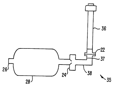
Referring now to Fig. 3, a schematic illustration of
a first alternative embodiment of a device 35 for impeding air
flow into a patient's lungs according to the present invention
is shown. The device 35 comprises an endotracheal tube 36
which is placed into the patient's trachea and provides a
ventilation passageway. Connected to the endotracheal tube 36
is a transition tube 38 which connects the endotracheal tube 36
to the ventilation bag 28. Although the endotracheal tube 36
is shown connected to the ventilation bag 28, the endotracheal
tube 36 can be used alone or in connection with the ventilation
bag 28. The ventilation bag 28 can comprise any type of
ventilation source capable of ventilating the patient such as a
compressible or collapsible structure. Preferably, the
- ventilation bag 28 consists of an AMBU bag. Attached or
WO 95/13108 PCTlLTS94112870
13
connected to the end of the ventilation bag 28 is a one-way
ventilation valve 26. The ventilation valve 26 serves to
introduce air into the device 35. Attached or connected to the
transition tube 38 is an inflow pressure-responsive valve 24.
The inflow valve 24 is biased so that it opens when the
negative intrathoracic pressure in the patient's chest reaches
a threshold amount. As shown, only one inflow valve 24 is
included in the device 35. However, the invention is not
limited to only one inflow valve 24. Alternatively, a
plurality of inflow valves 24 could be connected in series
along the ventilation tube 38. The inflow valve 24 is also not
limited to being connected in the center of the transition tube
38, but may be positioned anywhere along the transition tube
38. The inflow valve 24 could be permanently attached to the
ventilation bag 28 or transition tube 38 or could be
detachable. Alternatively, the inflow valve 24 could be
connected to the ventilation bag 28 itself or to the
endotracheal tube 36.
The device 35 also contains a one-way expiration
valve 22 which allows for air to be expired from the patient's
lungs. This generally occurs during the compression phase of
ACD-CPR. To insure that the air expired from the patient's
lungs will exit through the expiration valve 22, a one-way fish
mouth valve 37 (the preferred valve) or any other type of one-
way valve can be placed between the inflow valve 24 and the
expiration valve 22. Alternatively, the inflow valve 24 itself
may be configured as a one-way valve. In either case, air
flowing from the endotracheal tube 36 toward the ventilation
bag 28 will be forced to expire through the expiration valve
22.
The device 35 may be further modified to include a
pressure-responsive expiration valve 39 (not shown) located
between the endotracheal tube 36 and the transition tube 38.
The pressure-responsive expiration valve works in a reverse
manner to that of the inflow valve 24. Specifically, the
pressure-responsive expiration valve is biased so that during
the compression step of ACD-CPR, air will be allowed to expire
from the patient's lungs only when the intrathoracic pressure
WO 95!13108 PCT/US94/12870
14
reaches a threshold amount. The increase in intrathoracic
pressure caused by the pressure-responsive expiration valve 39
during compression may assist in forcing more blood out of the
thorax and reduce atelectasis of the lungs.
The purpose of the ventilation bag 28 is to provide
ventilation to the patient during ACD-CPR. When the
ventilation bag 28 comprises an AMBU bag or similar bag used
for ventilation, ventilation of the patient may be performed by
merely squeezing the AMBU bag with a human hand. This forces
air to the patient's lungs as desired.
Referring to Fig. 4A, a second alternative embodiment
of the device for impeding air flow into a patient's lungs
according to the present invention is shown. This particular
embodiment is a modified and improved endotracheal tube.
Hence, the second alternative embodiment comprises an
endotracheal tube 36 having two lumens at its proximal end.
The first lumen is an outflow lumen 40, and the second lumen is
an inflow lumen 42. Located within outflow lumen 40 is a one-
way pressure-responsive expiration valve 44 which operates in a
manner similar to that discussed in connection with Fig. 3,
except that the expiration valve 44 is specifically designed as
a one-way valve. Located within inflow lumen 42 is a one-way
pressure-responsive inflow valve 45 which operates to impede
air flow to the lungs as discussed in connection with Fig. 3,
except that the inflow valve 45 is also specifically designed
as a one-way valve. Also shown in inflow lumen 42 and outflow
lumen 40 is an O-ring 46 which will be discussed subsequently.
Inflow valve 45 and expiration valve 44 are designed as one-way
valves so that during the compression phase, air can only be
expired from the patient through the endotracheal tube 36 when
the intrathoracic pressure reaches a threshold amount. At that
moment, expiration valve 44 opens and air expires from the
patient through the outflow lumen 40. During decompression,
air cannot flow through the endotracheal tube 36 to the
patient's lungs until the negative intrathoracic pressure
reaches a threshold amount. At that moment, inflow valve 45
opens allowing air to flow through inflow lumen 42 to the
WO 95!13108 ; PCT/US94112870
patient's lungs. Air is prevented from entering through the
outflow lumen 40 because of the one-way expiration valve 44.
Ventilation is possible with the embodiment disclosed
in Figs. 4A and 4B if the inflow lumen 42 is connected to a
5 ventilation source such as a ventilation bag. When the
ventilation bag is squeezed, air is allowed to flow through the
inflow lumen 42, through the endotracheal tube 36, and to the
patient's lungs. In this embodiment, expiration valve 44 is
designed so that during ventilation, expiration valve 44 will
10 remain temporarily closed preventing air flowing through inflow
lumen 42 escape through outflow lumen 40.
Fig. 5A is a schematic view of a one-way inflow valve
45 used in a device for impeding air flow according to the
present invention. The inflow valve 45 operates so as to allow
15 air only to flow in one direction. As shown, the spring biased
inflow valve 45 is completely open. However, the invention
also functions properly if the spring biased inflow valve 45 or
the spring biased expiration valve 44 are not fully open. Upon
successful completion of ACD-CPR, the O-ring 46 that is
positioned above the inflow valve 45 is repositioned so that
inflow valve 45 is held open as shown in Fig. 5B. Such a
positioning of O-ring 46 allows for unimpeded air flow to the
patient once there is a return of spontaneous circulation and
the inflow valve 45 is no longer needed. An O-ring 46 is also
used in a similar manner to lock the one-way expiration valve
44 in an open position upon return of spontaneous circulation.
Fig. 5C illustrates the one-way inflow valve 45 in a closed
position. When closed, the inflow of air through the inflow
valve 45 is occluded.
Fig. 6A illustrates an inflow valve 47 that is spring
biased and an expiration valve 48 that is also spring biased.
The inflow valve 47 and the expiration valve 48 are connected
in series and may be used in the first alternative embodiment
as discussed in connection with Fig. 3, or with the preferred
embodiment discussed following in connection with Fig. 9. As
shown in Fig. 6C, during the active decompression step, the
inflow valve 47 is biased such that it will open when the
negative intrathoracic pressure reaches a threshold amount.
PCT/US94112870
WO 95113108
16
During the compression phase of ACD-CPR the expiration valve 48
will open to allow air to expire from the patient's lungs when
the intrathoracic pressure within the patient°s chest reaches a
threshold amount as shown in Fig. 6B. Since neither inflow
valve 47 nor expiration valve 48 are one-way valves, a fish
mouth valve 37 used in connection with a one-way expiration
valve 22 as discussed in connection with Fig. 3 must be used.
Other valves designed upon a similar principle as the fish
mouth valve combination with a one-way expiration valve could
also be used. Only one inflow valve 24 and one positive end
pressure valve 44 are shown in Figs. 6A-6C. However, a
plurality of inflow valves 47 and/or expiration valves 48 may
be connected in a permanent or detachable manner in series to
impede the inflow and outflow of air.
Although the valves in Figs. 6A-6C are shown as being
spring-biased, any other valves designed upon a similar
principle would work equally as well. The use of such valves
as disclosed in Figs. 6A-6C is only one embodiment and valves
constructed according to various other methods and materials is
also within the scope of the invention.
As shown in Fig. 7, the inflow valve 47 and the
expiration valve 48 may be combined into one joint valve 49 as
shown. The joint valve 49 will operate in a manner similar to
the two valves 47 and 48 as described in connection with Fig.
6.
Fig. 8 illustrates a flow restricting orifice 50 to
be used to either impede the air flow into or out of a
patient's lungs. The flow restricting orifice 50 operates so
that during the decompression step of ACD-CPR air flow is
impeded from entering into the patient's lungs, thus increasing
the negative intrathoracic pressure. During the compression
step, the flow restricting orifice 50 operates to increase the
thoracic pressure in the patient°s chest by restricting air
from existing from the patient's lungs.
Fig. 9 illustrates an exemplary embodiment for
- impeding air flow into a patient's lungs according to the
present invention. As shown, the device 51 comprises a
ventilation bag 28 that is connected to a facial mask 52 by an
WO 95!13108 PCT/US94/12870
17
inflow valve 24 and an expiration valve 22. Although the
facial mask 52 is shown connected to the ventilation bag 28,
the facial mask 52 can be used alone or in connection with the
ventilation bag. Between the inflow valve 24 and the
expiration valve 22 is a one-way fish mouth valve 37 or any
other type of one-way valve to prevent air from exiting the
patient's lungs and flowing to the ventilation bag 28. The
ventilation bag 28 also contains a one-way ventilation valve 26
for allowing air to inflow into the device 51. The exemplary
embodiment operates in a manner similar to that of the first
alternative embodiment as discussed in connection with Fig. 3.
However, instead of inserting an endotracheal tube 36 into the
patient's airway, the facial mask 52 is placed over the
patient's mouth and nose. A facial strap 54 (not shown) may
also be wrapped around the head of the patient to secure the
ventilation mask 52 to the patient's face.
Device 51 is preferably used in connection with an
oral airway device (not shown) to prevent the patient°s airway
from becoming occluded, e.g. by the patient's tongue. The oral
airway device can be any device that is used to keep the
patient's tongue from slipping backward and occluding the
airway. Preferably, the oral airway device will be curved and
constructed of a plastic material and may or may not be
attached to the device 51.
During the decompression phase of ACD-CPR, air is
prevented from entering into the patient's lungs through the
threshold inflow valve 24 thus increasing the negative
intrathoracic pressure. During the compression phase, air is
allowed to expire from the patient's lungs through the
expiration valve 22. Also, the patient can be ventilated
during ACD-CPR by manually squeezing the ventilation bag 28.
Consequently, the preferred embodiment serves to enhance
cardiopulmonary circulation by increasing the negative
intrathoracic pressure to force more blood into the chest from
the peripheral venous vasculature.
Figs. 10A - lOC show another embodiment of the
present invention which allows the patient to be ventilated by
bypassing the impeding step. The embodiment comprises a
WO 95/13108 PCT/US94I12870
18
ventilation tube 60 with a proximal end 62 and a distal end 64
that is connected to the patient. The ventilation tube 60 has
a one-way bypass valve 66 and a one-way pressure responsive
valve 68. The ventilation tube 60 may also have a manual
switch 70 attached to the bypass valve 66 and extending through
aside of the ventilation tube 60. As shown in Fig. 10A, the
switch 70 may be set in a closed position so that the one-way
pressure responsive valve 68 opens when the threshold pressure
of the valve 68 has been exceeded. At this point, the valve 68
opens allowing for ventilation of the patient. As shown in
Fig. 10B, the one-way pressure responsive valve 68 may be
bypassed altogether by manually placing the switch 70 in the
open position so that the bypass valve 66 is opened allowing
air to flow to the patient. Fig. lOC illustrates the operation
of the bypass valve 66 with the switch 70 in an inactive mode.
Here, the rescuer performing ventilation may do so without
added resistance from the impedance step as in Fig. 10A.
Instead, bypass valve 66 opens only when the pressure at the
proximal end of the tube 62 is greater than atmospheric
pressure (0 mmHg), preferably in a range from about 0 mmHg to 5
mmHg. During decompression of the patient's chest, the one-way
bypass valve 66 remains closed unless atmospheric pressure is
exceeded. Thus, the patient is ventilated only when the
rescuer performing ventilation causes the pressure at the
proximal end of the tube 62 to exceed atmospheric pressure.
The function of the one-way bypass valve 66 may be performed by
many different threshold valve designs which are known in the
art.
Although the foregoing invention has been described
in some detail by way of illustration and example, for purposes
of clarity of understanding, it will be obvious that certain
changes and modifications may be practiced within the scope of
the appended claims.