Note: Descriptions are shown in the official language in which they were submitted.
21 74999
'
- - . P-286 1
PRE-~ILLABLE SYRINGE AND STOPPER
10ASSEMBLY T~EREFOR
BACKGROUND OF TE~ INVI~NTION
1. Field of the Invention. The subject invention relates
15- generally to pre-filled syringes and to stoppers for such syringes.
2. Description of the Prior Art. The prior art syringe
includes an elongate barrel having opposed ~ al and distal ends
and a fluid receiving chamber therebetween. The distal end of the
prior art syringe barrel includes a small diameter passage that
20 communicates with the fluid receiving cha...ber and with the lumen
of a piercing elemPnt, such as a pointed needle cannula or a blunt-
ended c~nm-l~, that is mounted to the syringe barrel. The proximal
end of the prior art syringe barrel is generally open for slidably
receiving a plunger. The plunger typically includes a distal end
25 configured to mate with a rubber stopper that is in sliding fluid-tight
engagement with the inner wall of the chamber. A distal force on
the plunger and stopper urges fluid in the chamber through the
passage of the syringe barrel and through the needle that
communicates with the passage. A proximal force on the plunger
30 and stopper urges fluid proximally through the passage and into the
chamber of the prior art syringe barrel.
Many prior art syringes remain empty until shortly prior to
use. These prior art syringes are used by placing the needle in
communication with a drug and moving the plunger proximally to
35 aspirate the drug into the chamber of the syringe barrel. The drug
2 1 7 4 9 (~ q P-2861
(2)
may then be ~ s~ered by placing the distal end of the needle in
cGn~ tion with the patient or with an IV set or other device,
and urging the plunger distally to expel the drug from the syringe
barrel.
The filling of a syringe ;.. e~;Alçly prior to use requires the
time, skill and attention of the health care worker. Health care
wo,ke,~ often work under e,nelgel-.;y cir~ ces with numerous
~imlllt~neous dçm~n-is for their time, skill and attention At the very
least, filling a hypodermic syringe immediately prior to use creates
an inconvenience for the he~lthc~re worker, and can create the
potential for improper selection and dosing of a drug.
Frictional forces between the rubber stopper and the syringe
barrel can be significant and can impede a slow, predictable and
accurate flow of drug into or out of the syringe barrel. As a result,
most prior art syringes employ a low friction material or lubricant,
oftentimes a silicone-based lubricant such as a silicone oil, to
f~cilit~te the sliding movement of the stopper in the syringe barrel.
The lubricant may be applied as a coating over the stopper or may
be applied to the walls of the chamber in the syringe barrel.
To avoid problems associated with filling the syringe
immediately prior to use, pharm~ceutical companies sometimes
prefer to ship medic~m~nt~ in pre-filled syringes. The pre-filled
syringes are approplialely sealed, clearly labeled, and shipped to
health care facilities in properly measured doses. Thus, a healthcare
worker avoids many of the steps associated with point of injection
syringe filling. The healthcare worker merely accesses an
appropl.dle pre-filled syringe and injects the required dose without
the above described inconveniences associated with filling the
syringe immediately prior to use. Pre-filled syringes are widely
used for a broad range of drugs that have an acceptably long shelf
life. However, owing to certain factors such as the duration of
storage which pre-filled syringes might sustain, many drugs that are
2174~(tq P-2861
(3)
otherwise applopl;ale for pre-filled syringes may so~ ..es be
inco"lpdlil,l~ with the lubricant or low friction material, such as
silicone oil, used to f~cilit~te the sliding movement of the stopper
through the syringe barrel. For i~ ce, protein based drugs or
5 drugs based on biogenetic technology may sometim~S display
col"palil.ility fiiffic llties respective of the silicone employed as a
syringe lubricant.
The prior art inr,l~des stoppers with l~min~ted films or
coatings to reduce friction without using silicone-based lubricants.
For example, U.S. Patent No. 5,009,646 teaches l~ a
rubber elastic body with a tetrafluoroethylene resin, an
ethylenetetrafluoroethylene resin or a UHMW polyethylene resin.
These l~min~ted stoppers may work well for syringes that are filled
immediately prior to use. However, the lA~in~led materials may
tend to creep after placement in the syringe barrel. As a result,
microrh~nnel~ are opened that may permit the drug in the syringe
barrel to communicate with ambient air. Thus, the adequacy and
effectiveness of the drug can be colllprolllised by using these prior
art stoppers l~min~ted with a non-silicone, low friction m~tçri~l
In view of these problems, certain drugs that would
otherwise be appropliate for pre-filled syringes must be filled
imme(1i~tely prior to use by the health care worker to avoid
co~ n ~ the drug, either because of the presence of lubrican+s
or low friction materials such as silicone-based lubricants or
cont~min~tion owing to unwanted communication with the ambient
atmosphere.
SUMMARY OF THE INVENTION
The subject invention is directed to pre-filled syringes and,
in particular, to stopper assemblies for pre-filled syringes. The
syringe of the subject invention may include a syringe barrel with
opposed pro~illlal and distal ends and a fluid receiving chamber
` 2~74999 P-2~61
(4)
thelel~elwæn. The distal end of the syringe barrel may include a tip
having a narrow fluid passage eyt~n~ the.ellu~ugh and
communicating with the chamber of the syringe barrel. A piercing
.o1em~.nt such as a sharply pointed needle cannula or a blunt-ended
5 cannula may be securely mounted to the tip such that the lumen
through the piercing elem~nt communicates with the chamber of the
syringe barrel. A protective cap may be sealingly engaged over the
distal end of the syringe barrel. The protective cap functions to seal
the distal end of the syringe barrel and to prevent ar~ciclçnt~l sticks
10 with a piercing element that may be premounted thereon. The
pro~ill.al end of the syringe barrel is open for slidably receiving a
plunger and stopper assembly therein.
A specified dose of a s~1ected drug is pre-filled into the
syringe barrel for subsequent slfip-l.t;.ll to a medical facility and
15 storage at the medical facility until the drug is needed. The end of
the syringe barrel pl oxilllal of the drug dosage is protectively sealed
by a sealing assembly in accordance with the present invention.
The sealing assembly in~ des proxilllal and distal stoppers, which
may be either spaced from one another, rest adjacent to one another
20 or disposed interengaged with one another. The distal stopper may
be formed from a resilient elastomeric material. To facilitate
sliding, a low friction material may be l~min~te~l, sealed, glued, or
otherwise disposed on the distal stopper. To avoid col.l~.,.;n~ting
effects on the drug held in the syringe barrel, the low friction
25 material should be substantially free of materials known to have
adverse effects on drugs as hereinbefore recited, including silicone-
based materials such as silicone oil. The material coated to the
elastomeric material of the distal stopper is selected to exhibit
acceptable sliding friction forces relative to the wall of the syringe
30 barrel.
As noted above, silicone-free l~min~ted or coated stoppers
have been used in prior art syringes that are filled immediately prior
21 749q9
P-2861
, .
(5)
to use, but have not been used for pre-filled ~y~ ges due to the
tendency ofthe l~min~te or coating on the stopper to creep so as to
permit microchannels to open. To offset this deficiency of the prior
art, the pro~nal stopper is formed from a known elastomer that is
appropliately lubricated with a lubricant. One example of such a
lubricant is a silicone-based lubricant such as polydi"~tl,ylsiloxane
silicone oil. The pro~l,lal stopper functions as an absolute
microbiological barrier that offsets the above noted sealing
deficiencies of the distal barrier. Because the lubricating tre~tm~nt
of the ploA""al stopper is separated from the drug by the distal
stopper, the proximal stopper can be treated with any convenient
lubricating material, in~ ling silicone-based lubricants such as
silicone oil, without undue risk of co.,l~ ion to the drug held in
the syringe barrel. Hence, contact between the drug and the
lubricant is dramatically reduced if not çlimin~tçd so as to avoid the
aforementioned problems.
The lubricating tre~tm~.nt of the proximal stopper can be
achieved by applying the lubricant directly to the proximal stopper
or by applying the lubricant to the inner walls of the syringe barrel
after the distal stopper has been positioned.
BRIEF DESCRIPTION OF THE DR~WINGS
Fig. 1 is a longitudin~l cross-sectional view of a pre-filled
syringe with the distal stopper of the subject stopper assembly.
Fig. 2 is a longitudinal cross-sectional view similar to Fig. 1,
but showing both the distal and proximal stoppers of the subject
stopper assembly.
Fig. 3 is a cross-sectional view similar to Fig. 2, but
showing a second embodiment of the stopper assembly.
Fig. 4 is a cross-sectional view similar to Figs. 2 and 3, but
showing a third embodiment of the stopper assembly.
21 74~9~ P-2861
-
(6)
Fig. 5 is a cross-sectional view similar to Figs. 2-4, but
showing a fourth embodiment of the stopper ass~ ..lbly.
Fig. 5a is an alternate configuration of the embodiment of
Fig. 5.
S Fig. 6 is a cross-sectional view similar to Figs. 2-5, but
showing a fi~h embodiment of a stopper assembly.
DETAILED DESCRIPTION OF THE PREFERRED
EMBODIMENT
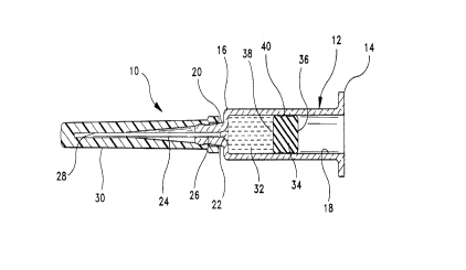
Turning now to the drawings, wheleill like numerals denote
like components, a hypodermic syringe in accordance with the
subject invention is identified generally by the numeral 10 in Figs. 1
-- and 2. Syringe 10 inc1udes a generally cylindrical syringe barrel 12
having opposed plo~n,al and distal ends 14 and 16 and a fluid
receiving chamber 18 therebetween. The syringe barrel 12 can be
formed of applop,i~le medical grade glasses, plastics, metals, or the
like materials known to the skilled artisan. Distal end 16 of syringe
barrel 12 in~ des an elongate tip 20 having a passage 22 ~xtçn-ling
therethrough and con""ul~icating with chamber 18 of syringe barrel
12.
A piercing element 24 is disposed at the distal end 16 of the
syringe barrel 12. The piercing element 24 includes a proxinlal end
26 mated to the syringe b~rrel 14 and a distal end 28. As has been
previously explained, it is within the purview of the present
invention that the piercing element 24 can entail sharply pointed
needle c~nn~ e, or blunt-ended c~nn~ e7 such as those employed
with the so-called needleless systems. For purposes of illustration
but not of limitation, as herein shown, the piercing element 24 is
herein formed as a sharply pointed, elongate needle cannula 24
including the proximal end 26, a sharply pointed distal end 28 and a
lumen e~tçn-ling therebetween. Proximal end 26 of needle cannula
24 is rigidly mounted to tip 20 of syringe barrel 12, such that the
-`` 21 74999
P-2861
-
(7)
lumen through needle c~nmll~ 24 communicates with p~ge 22
and cl~ l)er 18 of syringe barrel 12.
An elongate cap 30 is mounted over needle cannula 24 and
is releasably engaged to tip 20 of syringe barrel 12. Cap 30, which
S can be formed from a rigid material such as plastic, or which can be
formed from a flexible material such as rubber, or from lilce
materials or collll)inalions known to the skilled artisan, may be
configured with appropliale dimensionary sealing elements, or the
like, for closing the lumen of the piercing ~olem~nt 24 in fluid
co.lll,lunication with the drug and to otherwise protectively seal,~
engage or surround sharply pointed distal end 28 of needle c~nnlll~
24 and isolate same from the ambient environment. Thus, cap 30
prevents ambient air from colllmul~icating with the lumen through
needle cannula 24.
I ~ A predetermined dose of a selected drug 32 is pre-filled into
chamber 18 of syringe barrel 12, and a distal stopper 34 is slidably
advanced in chamber 18 toward drug 32. As illustrated, distal
stopper 34 is formed of generally cylindrical shape to conform to
the generally cylindrical ~iim~.n~ions of syringe barrel 12. Stopper
34 includes opposed proxilllal and distal ends 36 and 38 and a side
surface 40 ~xt~ntling therebetween. As the skilled artisan will
appreciate, side surface 40 of distal stopper 34 may be
eharacterized by a plurality of cil~;ull-relel~l;ally .oxten~ling ribs.
However, other embodiments of the distal stopper may have a
substantially smooth cylindrical side surface. Distal stopper 34 is
preferably formed from an elastomeric material and, to effect good
sliding action with the syringe barrel, l~min~ted or coated with a
material selected to exhibit low friction characteristics against the
glass walls of syringe barrel 12. The material l~min~te~l or coated
to the distal stopper 34 should not exhibit detrimental effects to the
drug as hereinbefore mentioned and in particular, should be free of
silicone-based materials such as silicone oil. For instance, the
21 74999 P-2861
(8)
l~min~te or coating may be se~e~ed from the group collsi~lillg of
tetrafluoroethylene resin, an ethyl~let~ nuoroethylene resin, a
UHMW polyethylene resin, or various carbon coatings. Thus,
distal stopper 34 will be able to slide distally in chamber 18 for
S initial positioning ~ t drug 32 and for subsequently urging
drug 32 through the lumen of needle c~nmll~ 24. However, as
noted above, the low friction material l~min~ted or coated onto
distal stopper 34 has been known to risk creep over time, and hence
may not be a perfect microbiological barrier for sealing drug 32 in
10 pre-fflled syringe 10.
The above-referenced potential ~lefil~,iency of distal stopper
34 is overcome by a prox.",al stopper 42 which, as shown in Fig. 2,
cooperates with distal stopper 34 to define a stopper assel.,bly 44.
Plo~il..al stopper 42 also is of generally cylindrical configuration
15 and includes opposed proxihllal and distal ends 46 and 48
respectively and a side surface 50 eYt~nrlin~ therebetween.
P~oxilllal end 46 of pro~i...al stopper 42 includes mounting means
for secure engagement with a plunger 52 of pre-filled syringe 10.
As depicted herein, the mounting means on p.o~.lal stopper 42
20 comprises a threaded aperture formed in pro~ilal end 46 of
proximal stopper 42. A corresponding array of threads 54 is
formed on the distal end of plunger 52. Other mounting means can
be ~qmployed, however. Distal end 48 of pro~-~llal stopper 42 is
generally planar in the embodiment depicted in Fig. 2, and can be
urged into abutting engagement with proximal end 36 of distal
stopper 34.
Proximal stopper 42 may be formed from rubber or other
elastomeric material c~l ibi~ g microbiological sealing capabilities.
Additionally, because proximal stopper 42 will be separated from
drug 32 by the distal stopper 34, the ploximal stopper 42 and/or
syringe barrel 12 may be approp.iately treated with many
convenient lubricating materials, including silicone-based lubricants
"- 21 749Y~
P-2861
(9)
such as silicone oil, to f~r~ te s1iding movement. One silicone oil
applicable to the stopper 42 may entail polydimethylsiloxane. In
particular, a silicone coating may be applied to at least the generally
cylindrical side surface 50 of pro~llal stopper 42 prior to inse,ling
S pro~lllal stopper 42 into syringe barrel 12. Alternatively, a silicone
spray may be applied to the interior surface of chamber 12 after
having positioned distal stopper 34 as shown in Fig. 1. With either
optional embodiment, distal stopper 34 functions as a barrier that
prevents contact of the lubricant such as silicone oil and from the
region of prox~"al stopper 42 with drug 32. Plo~al stopper 42
e~ibits microbiological sealing, and avoids problems of leaching
that might be displayed by distal stopper 34 over time in pre-filled
syringe 10.
Pre-filled syringe 10 can be used substantially in the
15 standard manner by merely removing cap 30 and urging plunger 52
distally to expel a selected amount of drug 32 through the lumen of
needle cannula 24 and into a patient. The sliding distal movement
of plunger 52 can be carried out easily in view of the low friction
characteristics of the l~min~te or coating on distal stopper 34 and in
20 view of the lubricant treatment of proximal stopper 42. However,
pre-filled syringe 10 can be stored for a desirably long period of
time in view of the exceptional microbiological sealing provided by
elastomeric pr~ ,lal stopper 42 and in view-o~ tke barrier function
pelrolllled by distal stopper 34 that separates drug 32 from the
25 lubricant such as silicone oil in pl o;~ y to proximal stopper 42.
Fig. 3 shows pre-filled syringe 10 substantially as described
and illustrated above, but with an alternate stopper assembly 144.
More particularly, stopper assembly 144 includes a distal stopper
134 having an open proximal end 136, a closed distal end 138 and a
30 generally tubular sidewall 140 extending therebetween. Stopper
assembly 144 further includes a proximal stopper 142 with a
pro~lllal end 146 substantially identical to proximal end 46 of
`- 217499q P-2861
(10)
proA",.al stopper 42 des~ ed and illustrated above. However,
ploAill,al stopper 142 further incllldes a distal end 148 ~l~fining an
elongate projection ~xtenl1in~ into open distal end 136 of distal
stopper 134 and cont~cti~ the wall defined by distal end 138.
Tubular sidewall 140 of distal stopper 134 will exert ~deq~l~te
resilient forces against the cylindrical wall of syringe barrel 12 to
function as an Adeqll~te barrier between drug 32 and distal stopper
142. However, when plunger 152 is ~ctuAted by a user, the hollow
configuration of distal stopper 134, coupled with contact between
distal stopper 134 and distal end projection 148 of pro~",al stopper
142 will cause a slight d ;;r~"l"alion and elongation of distal stopper
134. Distal stopper 134 will thus be slightly deformed away from
the surface of syringe barrel 12, thereby s~ ;AIIy red~l.ing
forces between distal stopper 134 and syringe barrel 12 and, hence,
resl-lting in lower required forces to urge distal stopper 134 distally
for expelling drug 32 from chamber 18. In this case, it will be
realized that distal stopper 134 need not necessarily be formed of a
low-friction material. Hence, the alternate stopper assembly shown
in Fig. 3 provides the sealing advantages referred to with respect to
the Fig. 1 and 2 embodiment but with a significantly lower force
required to move plunger 152 distally.
Fig. 4 shows pre-filled syringe 10 subst~nti~lly as described
~nd illustrat~.d above, but employing a third stopper asse",l)ly 244.
Stopper assembly 244 inc!lldes an axially short distal stopper 234
having a proximal end 236 defining a locking projection 237
thereon. Distal end 238 and side 240 of distal stopper 234 are
structurally similar to those of distal stopper 34 shown in Fig. 1
above. Stopper assembly 244 further includes a pro~illlal stopper
242 having a plo~il..al end 246 substantially identical to that of
proximal stopper 42 and a distal end 248 having a locking
inrlçr~t~tion 249 formed therein. In this embodiment, pro~
stopper 242 is siliconized. Indentation 249 in distal end 248 of
21749r39 P-2861
(1 1)
ro~ al stopper 242 is then lockingly engaged with projection 237
on prc,~i,ll~l end 236 of distal stopper 234. Th~,~ller, the r..l;~h~d
assembly 244 is introduced into the syringe barrel 12. Plunger 250,
which can be mated to pro~lllal stopper 242 before or after
5 pre~alalion of the finished assembly 244, is used to slidably
advance stopper assembly 244 as previously des.j,il,ed. The pre-
asselllbly of ~lo~illlal and distal ~7loppel~ 242 and 234 respectively
can achieve certain assembly and m~nllf~ctllring efficiencies.
Furthermore the relatively short axial length of distal stopper 234
10 relative to plo~ lal stopper 242 can result in lower sliding forces
for a lvancing p1unger 248 distally.
A fourth stopper assembly ;s illustrated in Fig. S and is
identified generally by the numeral 344. Stopper asselll~ly 344
includes a distal stopper 334 s~sl~lll;ally identical to distal stopper
34 illustrated in Figs. 1 and 2. Stopper assembly 344 further
in- Iu(les a proximal stopper in the form of a toroid and generally
indicated by the numeral 342. The toroidally-shaped stopper 342
may take the form of an O-ring; however, other cross-sections such
as square, ovoid, or the like are envisionable. Stopper 342 is
applopliately lubricated to achieve low frictional characteristics
relative to internal walls of syringe barrel 12. Stopper assembly 344
is used with a plunger 350 having a distal end 352 with an annular
groove 354. As illustrated, the toroidallv-shaped pr~lnal stopper
342 is resiliently engaged in groove 354 of plunger 350. Distal end
352 of plunger 350 with the proximal stopper 342 engaged thereon
can be inserted into pre-filled syringe 10 such that distal end 352 of
plunger 350 engages proximal end 336 of distal stopper 334.
Alternately, as seen in Figure 5a, toroidal ploxinlal stopper 342 and
the distal stopper 334 may be disposed, affixed, or othenvise
attached adjacent one another, with plunger 350 insertable therein
and forming a sealing area 351 with proximal stopper 342.
-~ 21 7499~ P-2861
(12)
Fig. 6 shows a further alternate embodiment that may be
used in con~ a~ion with ~1e~ of the Fig. 2 embodiment and/or
the Fig. 4 embodiment. In particular, Fig. 6 illustrates a pre-filled
syringe 10 subst~nti~lly identic~l to the pre-filled syringe of Fig. 1.
5 A distal stopper 434 subst~nti~lly id~ntic~l to the distal stopper in
Fig. 1 is slidably inserted into open p,o~ al end 14 of syringe
barrel 12. As noted above, distal stopper 34 is formed from an
elastomeric material l~min~ted or coated with a non-silicone-based
material and ~;AI~ilillg desirable frictional characteristics relative to
10 syringe barrel 12. However, as noted above, distal stopper 34 may
not provide adequate sealing for long term storage of pre-filled
syringe 10. Adequate sealing is, however, provided by a stopper
442 or other type of enclosure, for in~t~nr~, a cap, a cover or the
like, which is sealingly eng~ged in open proxi",al end 14 of syringe
barrel 12. Stopper 442 is easily insertable and may be formed from
a rubber or elastomer that provides good microbiological sealing
capability. Immediately prior to use, stopper 442 is removed, and a
plunger without a stopper or with an applopliate lubricated stopper
or non-silicone l~min~ted stopper as set forth and described above
is inserted into open proximal end 14 of syringe barrel 12. The
plunger inserted immediately prior to use may be plunger 52 as
illustrated in Fig. 2 above or plunger 350 illustrated in Fig. 5 above.
As still a further alternate, the stopper 442 mav be use~l with the
hollow prox,lllal stopper 134 illustrated in Fig. 3 above. A~er
removal of the stopper, the plunger 152 and proximal stopper 142
shown in Fig 3 may then be slidably inserted into open proximal
end 14 of syringe barrel 12 for expelling drug 32 from chamber 18.
It will be appreciated and understood by those skilled in the
art that further and additional forms of the invention may be devised
without departing from the spirit and scope of the appended claims,
the invention not being limited to the specific embodiments shown.