Language selection

Search

Patent 2175024 Summary

Third-party information liability

Some of the information on this Web page has been provided by external sources. The Government of Canada is not responsible for the accuracy, reliability or currency of the information supplied by external sources. Users wishing to rely upon this information should consult directly with the source of the information. Content provided by external sources is not subject to official languages, privacy and accessibility requirements.

Claims and Abstract availability

Any discrepancies in the text and image of the Claims and Abstract are due to differing posting times. Text of the Claims and Abstract are posted:

  • At the time the application is open to public inspection;
  • At the time of issue of the patent (grant).
(12) Patent: (11) CA 2175024
(54) English Title: COUNTERWEIGHT TRAVELLING PULLEY
(54) French Title: POULIE MOBILE A CONTREPOIDS
Status: Expired and beyond the Period of Reversal
Bibliographic Data
Abstracts

English Abstract


-7-
The present invention is concerned with a conveyor wherein the
counterweight effect for maintaining the tension of the belt is realized by the travelling
pulley, thus allowing the removal of the counterweight on the underslung carriage. The
travelling pulley may be a conventional pulley filled with a heavy material such as lead,or
made of a series of weighted segments.


French Abstract

La présente invention a trait à un convoyeur dont l'effet de contre-poids pour maintenir la tension de la courroie est obtenu au moyen d'une poulie mobile, ce qui permet d'éliminer le contre-poids sur le chariot suspendu. La poulie mobile peut consister en une poulie traditionnelle remplie d'un matériau lourd, par exemple du plomb, ou d'une série de segments lestés.

Claims

Note: Claims are shown in the official language in which they were submitted.

- 6 -
WHAT IS CLAIMED IS:
1. A conveyor comprising:
- an endless belt mounted around two or more pulleys, wherein at least one of the
pulleys is a drive pulley;
- a travelling pulley slidably mounted on first substantially vertical supporting means
and acting as a counterweight for maintaining the tension of the belt when loaded, partially
loaded or unloaded,
- two additional pulleys, one on each side of the travelling pulley, each additional pulley
being secured to second supporting means, the belt passing over the first additional pulley,
under the travelling pulley thus supporting the weight of the travelling pulley, and over the
second additional pulley, whereby the tension of the belt is maintained by the vertical
movement of the travelling pulley.
2. A conveyor according to claim 1 wherein the travelling pulley is mounted to
a carriage which is slidably mounted on the first supporting means.
3. A conveyor according to claim 1 or 2 wherein the travelling pulley is filled with
a high density material.
4. A conveyor according to claim 3 wherein the material is a metal, alloy, metal
scrap, alloy scrap, rocks, or combinations thereof.
5. A conveyor according to claim 4 wherein the metal is lead.
6. A conveyor according to claim 1 or 2 wherein the travelling pulley comprises
a series of weighted segments.

Description

Note: Descriptions are shown in the official language in which they were submitted.


2 1 7 5024
1 -
TITI F
Counterweight travelling pulley
FlF~ n OF T~F ll~lVFNTION
S The present invention relates to a travelling pulley acting as a counterweight
for conveyor belts to take up belt slack and belt tensioning.
BACKGROUND OF T~F TNVFNTION
In a conveyor of any substantial length, the belt generally stretches when fullyloaded, but will m~int~in good contact with the drive pulley during operation. If the
conveyor is only partly loaded or completely unloaded, the stretched belt has to be gathered
up in order to reduce the slack in the belt and m~int~in adhesion between the drive pulley
and the conveyor belt.
In order to do so, a travelling pulley is inserted in the conveying system. A
counterweight is also attached or otherwise coupled to the travelling pulley to maintain the
tension of the belt, whether it is fully loaded, partly loaded or unloaded. The tension on the
belt can be varied during operation because the travelling pulley slides freely on a guide
substantially vertical and located under the belt.
A major disadvantage with the above arrangement is that the counterweight,
which hangs underneath the travelling pulley on a separate carriage, and thus, underneath
the conveyor, takes a signific~nt amount of space, thus requiring the conveyor to be
sufficiently high in the air to allow the n~cess~ry space for the counterweight to move.

21 75024
It would therefore be advantageous to be able to replace current
cou"~e~ ights with another belt tensioning and tightening weight taking less space since
conveyors frequently work in very confined spaces.
S SU~ RY OF T~F l~V~NTION
According to the present invention, there is now provided a belt tensioning and
travelling pulley movable substantially vertically underneath the conveyor. The invention
solves the problem of counterweights on separate carriage slung under the travelling pulley
since the travelling pulley now acts as the counterweight. More specifically, the present
10 invention is directed to a conveyor comprising:
- an endless belt mounted around two or more pulleys, wherein at least one of the
pulleys is a drive pulley;
- a travelling pulley slidably mounted on first substantially vertical supporting means
and acting as a counlelvveight for ~ g the tension of the belt when loaded, partially
15 loaded or unloaded,
- two additional pulleys, one on each side of the travelling pulley, each additional pulley
being secured to second supporting means, the belt passing over the first additional pulley,
under the travelling pulley, the belt thus supporting the weight of the travelling pulley, and
over the second additional pulley, whereby the tension of the belt is m~int~in~d by the
20 vertical movement of the travelling pulley.
In a preferred embodiment, the travelling pulley is filled with lead, or made of
a series of weighted segments.

2175024
- 3 -
DFTA~,FI) DF~CRlPTION OF T~lF, ll~V~NTION
The coun~lweight effect is realized by adding weight inside the travelling
pulley, thus allowing the removal of the underslung carriage counterweight. Further
features, objects and advantages will be evident from the following detailed description of
the preferred embodiments of the present invention taken in conjunction with theaccompanying drawings in which:
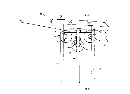
Figure 1 illustrates a side elevation partial view of a conveyor comprising a
travelling pulley according to the present invention;
Figure 2 is a view along axis 2-2 of Figure l;
Figure 3 illustrates a sectional view of the travelling pulley;
Figure 4 illustrates a second embodiment of the pulley, which comprises a seriesof weighted segments assembled to form a pulley; and
Figure 5 illustrates a weighted segment.
Referring to Figures 1 and 2, there is illustrated a conveyor 10 comprising a
belt 12, two pulleys 14 and 16 on each side of the travelling pulley 18. Pulley 18 travels
vertically on a carriage 19 having each end 26 and 28 adapted to slide on guides 20 and 22
with the help of a centre shaft 24 going through the pulley. Shaft 24 comprises a bearing
30 at each end thereof, each end being rotatably mounted on the c~rri~ge thus allowing the
free rotation of pulley 18 around the shaft. Pulleys 14 and 16 also comprise a centre shaft
32 and 34 with pairs of bearings 36 and 38 respectively at each end thereof to allow free
rotation. Each of the four bearings 36 and 38 is secured to a post 40. As the load varies
on the belt 12, pulley 18 may therefore move up and down to m~in~in the tightness of the
belt.

21 75024
As illustrated in Figure 3, to obtain the desired counterweight effect, a heavy
m;lte.ri~ll is introduced in the outer chamber 42 of pulley 18. To do so, holes (not shown)
are made on the extPrn~1 surface of the pulley, and the heavy m~tPri~l is introduced
thereafter. The easiest way is to introduce the m~tPri:~l in a molten form, to ensure that all
S chamber 42 is uniformly filled, and there wiU be no variation of weight in the pulley, thus
pr~v~ ing unh~l~nre~ pulleys. Preferred m~tPri~l~ should be cheap and have a high density
to obtain the heaviest pulley and the lower costs. Molten lead or lead scrap has been found
most preferable.
A further advantage of the present invention is that the sizes of the bearing and
shaft in the traveUing puUey are smaUer than those of a similar device with a h~n~Eing
counterweight. This is P~pl~inPd by the fact that in the present invention, the weight is
supported by the belt, instead of the bearings and shafts.
In operation, the endless belt passes over puUey 14 loops down around
travelling weighted pulley 18, and then comes up and over pulley 16. PuUey 18 wiU move
and down along the guide to m~int~in the belt sufficiently tight on the conveyor.
In a second embodiment, the f~ling of a puUey is replaced with a segmented
pulley (Figure 4). Each ~P~mPnt 44 has an opening 46 to allow the segment to be mounted
on a shaft 24 by s]ipping the segment and locking it thereon. In assembling such segments
to form a pulley, it may not be nPcess~ry to have aU segments made of heavy m~tP.ri~l,
depending on the weight required for m~int~ining the tension of the belt. Such heavy
m~teri:~l, as described above, may be inserted through one or more holes 48. Preferably,
openings 46 of each segment are instaUed so as to be 180~ from adjacent segments to

21 75~24
prevent a continuous slot that may cause problems. The assembled segments may then be
lagged to provide a more homogeneous surface for the belt to contact.
While the invention hAs been described in connection with specific embodiments
5 thereof, it will be understood that it is capable of further modifications and this application
is intended to cover any variations, uses or adaptations of the invention following, in
general, the principles of the invention and inchl(ling such departures from the present
disclosure as come within known or customary practice within the art to which the
invention pertains, and as may be applied to the ec~PntiAl features hereinbefore set forth, and
10 as follows in the scope of the appended claims.

Representative Drawing
A single figure which represents the drawing illustrating the invention.
Administrative Status

2024-08-01:As part of the Next Generation Patents (NGP) transition, the Canadian Patents Database (CPD) now contains a more detailed Event History, which replicates the Event Log of our new back-office solution.

Please note that "Inactive:" events refers to events no longer in use in our new back-office solution.

For a clearer understanding of the status of the application/patent presented on this page, the site Disclaimer , as well as the definitions for Patent , Event History , Maintenance Fee  and Payment History  should be consulted.

Event History

Description Date
Time Limit for Reversal Expired 2004-04-26
Letter Sent 2003-04-25
Letter Sent 2001-05-24
Inactive: Office letter 2001-04-05
Inactive: Office letter 2001-01-23
Revocation of Agent Requirements Determined Compliant 2001-01-23
Appointment of Agent Requirements Determined Compliant 2001-01-23
Inactive: Office letter 2001-01-23
Grant by Issuance 2000-12-26
Inactive: Cover page published 2000-12-25
Pre-grant 2000-09-27
Inactive: Final fee received 2000-09-27
Inactive: Application prosecuted on TS as of Log entry date 2000-09-21
Inactive: Status info is complete as of Log entry date 2000-09-21
Letter Sent 2000-09-20
Notice of Allowance is Issued 2000-09-20
Inactive: Approved for allowance (AFA) 2000-09-06
Application Published (Open to Public Inspection) 1997-10-26
Request for Examination Requirements Determined Compliant 1996-04-25
All Requirements for Examination Determined Compliant 1996-04-25

Abandonment History

There is no abandonment history.

Maintenance Fee

The last payment was received on 2000-02-01

Note : If the full payment has not been received on or before the date indicated, a further fee may be required which may be one of the following

  • the reinstatement fee;
  • the late payment fee; or
  • additional fee to reverse deemed expiry.

Patent fees are adjusted on the 1st of January every year. The amounts above are the current amounts if received by December 31 of the current year.
Please refer to the CIPO Patent Fees web page to see all current fee amounts.

Fee History

Fee Type Anniversary Year Due Date Paid Date
MF (application, 2nd anniv.) - standard 02 1998-04-27 1998-02-18
MF (application, 3rd anniv.) - standard 03 1999-04-26 1999-03-11
MF (application, 4th anniv.) - standard 04 2000-04-25 2000-02-01
Final fee - standard 2000-09-27
MF (patent, 5th anniv.) - standard 2001-04-25 2001-03-29
MF (patent, 6th anniv.) - standard 2002-04-25 2001-04-11
Owners on Record

Note: Records showing the ownership history in alphabetical order.

Current Owners on Record
NORANDA INC.
Past Owners on Record
GLENN LEBLANC
MARTIN HACHE
Past Owners that do not appear in the "Owners on Record" listing will appear in other documentation within the application.
Documents

To view selected files, please enter reCAPTCHA code :


To view images, click a link in the Document Description column. To download the documents, select one or more checkboxes in the first column and then click the "Download Selected in PDF format (Zip Archive)" or the "Download Selected as Single PDF" button.

List of published and non-published patent-specific documents on the CPD .

If you have any difficulty accessing content, you can call the Client Service Centre at 1-866-997-1936 or send them an e-mail at CIPO Client Service Centre.


Document
Description 
Date
(yyyy-mm-dd) 
Number of pages   Size of Image (KB) 
Abstract 1996-08-04 1 11
Claims 1996-08-04 1 32
Description 1996-08-04 5 169
Drawings 1996-08-04 5 79
Representative drawing 1997-11-18 1 6
Representative drawing 2000-12-04 1 7
Reminder of maintenance fee due 1997-12-29 1 111
Commissioner's Notice - Application Found Allowable 2000-09-19 1 163
Maintenance Fee Notice 2003-05-25 1 174
Correspondence 2000-09-26 1 37
Fees 2000-01-31 1 28
Correspondence 2001-01-22 1 8
Correspondence 2001-01-22 1 9
Correspondence 2001-05-23 2 59
Fees 2002-04-10 1 39
Correspondence 2000-12-28 3 116
Prosecution correspondence 1996-04-24 2 49