Sélection de la langue

Search

Sommaire du brevet 2175024 

Énoncé de désistement de responsabilité concernant l'information provenant de tiers

Une partie des informations de ce site Web a été fournie par des sources externes. Le gouvernement du Canada n'assume aucune responsabilité concernant la précision, l'actualité ou la fiabilité des informations fournies par les sources externes. Les utilisateurs qui désirent employer cette information devraient consulter directement la source des informations. Le contenu fourni par les sources externes n'est pas assujetti aux exigences sur les langues officielles, la protection des renseignements personnels et l'accessibilité.

Disponibilité de l'Abrégé et des Revendications

L'apparition de différences dans le texte et l'image des Revendications et de l'Abrégé dépend du moment auquel le document est publié. Les textes des Revendications et de l'Abrégé sont affichés :

  • lorsque la demande peut être examinée par le public;
  • lorsque le brevet est émis (délivrance).
(12) Brevet: (11) CA 2175024
(54) Titre français: POULIE MOBILE A CONTREPOIDS
(54) Titre anglais: COUNTERWEIGHT TRAVELLING PULLEY
Statut: Périmé et au-delà du délai pour l’annulation
Données bibliographiques
Abrégés

Abrégé français

La présente invention a trait à un convoyeur dont l'effet de contre-poids pour maintenir la tension de la courroie est obtenu au moyen d'une poulie mobile, ce qui permet d'éliminer le contre-poids sur le chariot suspendu. La poulie mobile peut consister en une poulie traditionnelle remplie d'un matériau lourd, par exemple du plomb, ou d'une série de segments lestés.


Abrégé anglais


-7-
The present invention is concerned with a conveyor wherein the
counterweight effect for maintaining the tension of the belt is realized by the travelling
pulley, thus allowing the removal of the counterweight on the underslung carriage. The
travelling pulley may be a conventional pulley filled with a heavy material such as lead,or
made of a series of weighted segments.

Revendications

Note : Les revendications sont présentées dans la langue officielle dans laquelle elles ont été soumises.


- 6 -
WHAT IS CLAIMED IS:
1. A conveyor comprising:
- an endless belt mounted around two or more pulleys, wherein at least one of the
pulleys is a drive pulley;
- a travelling pulley slidably mounted on first substantially vertical supporting means
and acting as a counterweight for maintaining the tension of the belt when loaded, partially
loaded or unloaded,
- two additional pulleys, one on each side of the travelling pulley, each additional pulley
being secured to second supporting means, the belt passing over the first additional pulley,
under the travelling pulley thus supporting the weight of the travelling pulley, and over the
second additional pulley, whereby the tension of the belt is maintained by the vertical
movement of the travelling pulley.
2. A conveyor according to claim 1 wherein the travelling pulley is mounted to
a carriage which is slidably mounted on the first supporting means.
3. A conveyor according to claim 1 or 2 wherein the travelling pulley is filled with
a high density material.
4. A conveyor according to claim 3 wherein the material is a metal, alloy, metal
scrap, alloy scrap, rocks, or combinations thereof.
5. A conveyor according to claim 4 wherein the metal is lead.
6. A conveyor according to claim 1 or 2 wherein the travelling pulley comprises
a series of weighted segments.

Description

Note : Les descriptions sont présentées dans la langue officielle dans laquelle elles ont été soumises.

2 1 7 5024
1 -
TITI F
Counterweight travelling pulley
FlF~ n OF T~F ll~lVFNTION
S The present invention relates to a travelling pulley acting as a counterweight
for conveyor belts to take up belt slack and belt tensioning.
BACKGROUND OF T~F TNVFNTION
In a conveyor of any substantial length, the belt generally stretches when fullyloaded, but will m~int~in good contact with the drive pulley during operation. If the
conveyor is only partly loaded or completely unloaded, the stretched belt has to be gathered
up in order to reduce the slack in the belt and m~int~in adhesion between the drive pulley
and the conveyor belt.
In order to do so, a travelling pulley is inserted in the conveying system. A
counterweight is also attached or otherwise coupled to the travelling pulley to maintain the
tension of the belt, whether it is fully loaded, partly loaded or unloaded. The tension on the
belt can be varied during operation because the travelling pulley slides freely on a guide
substantially vertical and located under the belt.
A major disadvantage with the above arrangement is that the counterweight,
which hangs underneath the travelling pulley on a separate carriage, and thus, underneath
the conveyor, takes a signific~nt amount of space, thus requiring the conveyor to be
sufficiently high in the air to allow the n~cess~ry space for the counterweight to move.

21 75024
It would therefore be advantageous to be able to replace current
cou"~e~ ights with another belt tensioning and tightening weight taking less space since
conveyors frequently work in very confined spaces.
S SU~ RY OF T~F l~V~NTION
According to the present invention, there is now provided a belt tensioning and
travelling pulley movable substantially vertically underneath the conveyor. The invention
solves the problem of counterweights on separate carriage slung under the travelling pulley
since the travelling pulley now acts as the counterweight. More specifically, the present
10 invention is directed to a conveyor comprising:
- an endless belt mounted around two or more pulleys, wherein at least one of the
pulleys is a drive pulley;
- a travelling pulley slidably mounted on first substantially vertical supporting means
and acting as a counlelvveight for ~ g the tension of the belt when loaded, partially
15 loaded or unloaded,
- two additional pulleys, one on each side of the travelling pulley, each additional pulley
being secured to second supporting means, the belt passing over the first additional pulley,
under the travelling pulley, the belt thus supporting the weight of the travelling pulley, and
over the second additional pulley, whereby the tension of the belt is m~int~in~d by the
20 vertical movement of the travelling pulley.
In a preferred embodiment, the travelling pulley is filled with lead, or made of
a series of weighted segments.

2175024
- 3 -
DFTA~,FI) DF~CRlPTION OF T~lF, ll~V~NTION
The coun~lweight effect is realized by adding weight inside the travelling
pulley, thus allowing the removal of the underslung carriage counterweight. Further
features, objects and advantages will be evident from the following detailed description of
the preferred embodiments of the present invention taken in conjunction with theaccompanying drawings in which:
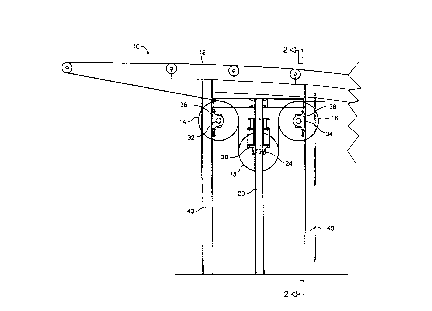
Figure 1 illustrates a side elevation partial view of a conveyor comprising a
travelling pulley according to the present invention;
Figure 2 is a view along axis 2-2 of Figure l;
Figure 3 illustrates a sectional view of the travelling pulley;
Figure 4 illustrates a second embodiment of the pulley, which comprises a seriesof weighted segments assembled to form a pulley; and
Figure 5 illustrates a weighted segment.
Referring to Figures 1 and 2, there is illustrated a conveyor 10 comprising a
belt 12, two pulleys 14 and 16 on each side of the travelling pulley 18. Pulley 18 travels
vertically on a carriage 19 having each end 26 and 28 adapted to slide on guides 20 and 22
with the help of a centre shaft 24 going through the pulley. Shaft 24 comprises a bearing
30 at each end thereof, each end being rotatably mounted on the c~rri~ge thus allowing the
free rotation of pulley 18 around the shaft. Pulleys 14 and 16 also comprise a centre shaft
32 and 34 with pairs of bearings 36 and 38 respectively at each end thereof to allow free
rotation. Each of the four bearings 36 and 38 is secured to a post 40. As the load varies
on the belt 12, pulley 18 may therefore move up and down to m~in~in the tightness of the
belt.

21 75024
As illustrated in Figure 3, to obtain the desired counterweight effect, a heavy
m;lte.ri~ll is introduced in the outer chamber 42 of pulley 18. To do so, holes (not shown)
are made on the extPrn~1 surface of the pulley, and the heavy m~tPri~l is introduced
thereafter. The easiest way is to introduce the m~tPri:~l in a molten form, to ensure that all
S chamber 42 is uniformly filled, and there wiU be no variation of weight in the pulley, thus
pr~v~ ing unh~l~nre~ pulleys. Preferred m~tPri~l~ should be cheap and have a high density
to obtain the heaviest pulley and the lower costs. Molten lead or lead scrap has been found
most preferable.
A further advantage of the present invention is that the sizes of the bearing and
shaft in the traveUing puUey are smaUer than those of a similar device with a h~n~Eing
counterweight. This is P~pl~inPd by the fact that in the present invention, the weight is
supported by the belt, instead of the bearings and shafts.
In operation, the endless belt passes over puUey 14 loops down around
travelling weighted pulley 18, and then comes up and over pulley 16. PuUey 18 wiU move
and down along the guide to m~int~in the belt sufficiently tight on the conveyor.
In a second embodiment, the f~ling of a puUey is replaced with a segmented
pulley (Figure 4). Each ~P~mPnt 44 has an opening 46 to allow the segment to be mounted
on a shaft 24 by s]ipping the segment and locking it thereon. In assembling such segments
to form a pulley, it may not be nPcess~ry to have aU segments made of heavy m~tP.ri~l,
depending on the weight required for m~int~ining the tension of the belt. Such heavy
m~teri:~l, as described above, may be inserted through one or more holes 48. Preferably,
openings 46 of each segment are instaUed so as to be 180~ from adjacent segments to

21 75~24
prevent a continuous slot that may cause problems. The assembled segments may then be
lagged to provide a more homogeneous surface for the belt to contact.
While the invention hAs been described in connection with specific embodiments
5 thereof, it will be understood that it is capable of further modifications and this application
is intended to cover any variations, uses or adaptations of the invention following, in
general, the principles of the invention and inchl(ling such departures from the present
disclosure as come within known or customary practice within the art to which the
invention pertains, and as may be applied to the ec~PntiAl features hereinbefore set forth, and
10 as follows in the scope of the appended claims.

Dessin représentatif
Une figure unique qui représente un dessin illustrant l'invention.
États administratifs

2024-08-01 : Dans le cadre de la transition vers les Brevets de nouvelle génération (BNG), la base de données sur les brevets canadiens (BDBC) contient désormais un Historique d'événement plus détaillé, qui reproduit le Journal des événements de notre nouvelle solution interne.

Veuillez noter que les événements débutant par « Inactive : » se réfèrent à des événements qui ne sont plus utilisés dans notre nouvelle solution interne.

Pour une meilleure compréhension de l'état de la demande ou brevet qui figure sur cette page, la rubrique Mise en garde , et les descriptions de Brevet , Historique d'événement , Taxes périodiques et Historique des paiements devraient être consultées.

Historique d'événement

Description Date
Le délai pour l'annulation est expiré 2004-04-26
Lettre envoyée 2003-04-25
Lettre envoyée 2001-05-24
Inactive : Lettre officielle 2001-04-05
Inactive : Lettre officielle 2001-01-23
Exigences relatives à la révocation de la nomination d'un agent - jugée conforme 2001-01-23
Exigences relatives à la nomination d'un agent - jugée conforme 2001-01-23
Inactive : Lettre officielle 2001-01-23
Accordé par délivrance 2000-12-26
Inactive : Page couverture publiée 2000-12-25
Préoctroi 2000-09-27
Inactive : Taxe finale reçue 2000-09-27
Inactive : Dem. traitée sur TS dès date d'ent. journal 2000-09-21
Inactive : Renseign. sur l'état - Complets dès date d'ent. journ. 2000-09-21
Lettre envoyée 2000-09-20
Un avis d'acceptation est envoyé 2000-09-20
Inactive : Approuvée aux fins d'acceptation (AFA) 2000-09-06
Demande publiée (accessible au public) 1997-10-26
Exigences pour une requête d'examen - jugée conforme 1996-04-25
Toutes les exigences pour l'examen - jugée conforme 1996-04-25

Historique d'abandonnement

Il n'y a pas d'historique d'abandonnement

Taxes périodiques

Le dernier paiement a été reçu le 2000-02-01

Avis : Si le paiement en totalité n'a pas été reçu au plus tard à la date indiquée, une taxe supplémentaire peut être imposée, soit une des taxes suivantes :

  • taxe de rétablissement ;
  • taxe pour paiement en souffrance ; ou
  • taxe additionnelle pour le renversement d'une péremption réputée.

Les taxes sur les brevets sont ajustées au 1er janvier de chaque année. Les montants ci-dessus sont les montants actuels s'ils sont reçus au plus tard le 31 décembre de l'année en cours.
Veuillez vous référer à la page web des taxes sur les brevets de l'OPIC pour voir tous les montants actuels des taxes.

Historique des taxes

Type de taxes Anniversaire Échéance Date payée
TM (demande, 2e anniv.) - générale 02 1998-04-27 1998-02-18
TM (demande, 3e anniv.) - générale 03 1999-04-26 1999-03-11
TM (demande, 4e anniv.) - générale 04 2000-04-25 2000-02-01
Taxe finale - générale 2000-09-27
TM (brevet, 5e anniv.) - générale 2001-04-25 2001-03-29
TM (brevet, 6e anniv.) - générale 2002-04-25 2001-04-11
Titulaires au dossier

Les titulaires actuels et antérieures au dossier sont affichés en ordre alphabétique.

Titulaires actuels au dossier
NORANDA INC.
Titulaires antérieures au dossier
GLENN LEBLANC
MARTIN HACHE
Les propriétaires antérieurs qui ne figurent pas dans la liste des « Propriétaires au dossier » apparaîtront dans d'autres documents au dossier.
Documents

Pour visionner les fichiers sélectionnés, entrer le code reCAPTCHA :


Pour visualiser une image, cliquer sur un lien dans la colonne description du document. Pour télécharger l'image (les images), cliquer l'une ou plusieurs cases à cocher dans la première colonne et ensuite cliquer sur le bouton "Télécharger sélection en format PDF (archive Zip)" ou le bouton "Télécharger sélection (en un fichier PDF fusionné)".

Liste des documents de brevet publiés et non publiés sur la BDBC .

Si vous avez des difficultés à accéder au contenu, veuillez communiquer avec le Centre de services à la clientèle au 1-866-997-1936, ou envoyer un courriel au Centre de service à la clientèle de l'OPIC.


Description du
Document 
Date
(aaaa-mm-jj) 
Nombre de pages   Taille de l'image (Ko) 
Abrégé 1996-08-04 1 11
Revendications 1996-08-04 1 32
Description 1996-08-04 5 169
Dessins 1996-08-04 5 79
Dessin représentatif 1997-11-18 1 6
Dessin représentatif 2000-12-04 1 7
Rappel de taxe de maintien due 1997-12-29 1 111
Avis du commissaire - Demande jugée acceptable 2000-09-19 1 163
Avis concernant la taxe de maintien 2003-05-25 1 174
Correspondance 2000-09-26 1 37
Taxes 2000-01-31 1 28
Correspondance 2001-01-22 1 8
Correspondance 2001-01-22 1 9
Correspondance 2001-05-23 2 59
Taxes 2002-04-10 1 39
Correspondance 2000-12-28 3 116
Correspondance de la poursuite 1996-04-24 2 49