Note: Descriptions are shown in the official language in which they were submitted.
217~6C
WO95/14120 PCT~S93/11424
METHOD OF MAKING MICROCHANNELED HEAT EXCHANGERS
UTILIZING SACRIFICIAL CORES
TECHNICAL FIELD
The present invention relates to microchanneled
heat e~ch~ngers and more particularly to a method of
forming microchanneled heat exchangers having a
manifold connected with a heat exchanger body.
10 BACKGROUND OF THE INVENTION
With the development of electronic circuit
technologies, particularly microelectronic circuits,
which are faster and have denser circuits, there is a
continually increasing demand for cooling techniques
15 which can dissipate the continually increasing
concentrations of heat produced at the circuit level by
integrated circuit chips, microelectronic packages,
other components and hybrids thereof. Moreover, such
microelectronic circuit technologies require greatly
20 improved heat removal from extremely small circuit
components. This situation is worsened when an array
of such chips are closely packed to one another. Thus,
the density of the chips proportionally increases the
heat which must be dissipated effectively by a cooling
25 technique.
In addition to the heat transfer demands on heat
exchangers, it is often required that a heat exchanger
be designed for a specialized component or use
environment, which may involve complex geometries.
30 Such specialized components and environments require
specialized heat exchangers.
Cooling techniques have been improved over the
recent years in both air cooling applications as well
as liquid cooling applications. In either case, it is
35 known to use either cooled forced air or cooled liquid
to reduce the temperature of a heat sink device
positioned adjacent to the circuit device to be cooled.
In another known technique, the circuit chips or
WO 95/14120 C~ 6tr~ PCT/US93/11424
packages are cooled by direct immersion cooling, which
is the act of directly bringing the chips or packages
into contact with the cooling liquid. Thus, no
physical walls separate the coolant from the chips.
5 These liquid cooling techniques, either of the heat
sink type or direct immersion cooling type, are
generally believed to be required in the above
described situations with dense very large-scale
integration (VLSI) circuits.
One known heat exchanger suitable for use in such
an environment is described in U.S. Patent No.
4,871,623 to Hoopman et al., issued October 3, 1989,
which is commonly owned by the assignee of the present
invention. The heat exchanger and method described in
15 the Hoopman et al. patent provides a plurality of
elongated enclosed electroformed channels that extend
through a sheet member between opposing major surfaces.
The sheet with the enclosed microchannels is made from
a mandrel or master having a plurality of elongated
20 ridges, wherein material is electrodeposited onto the
surfaces of the mandrel with the material being
deposited on the edges of the ridge portions at a
faster rate than on the surfaces defining inner
surfaces of the grooves until the material bridges
25 across between the ridge portions to envelope central
portions of the grooves and to form the sheet member.
Such sheet member includes a base layer with a
plurality of elongated projections, each of which
extends from the base layer into the grooves of the
30 mandrel, with each of the projections containing an
elongated enclosed microchannel. It is also disclosed
to then separate the sheet from the mandrel and
additionally to use the defined sheet member with its
base layer and elongated projections as the mandrel
35 onto which electrodepositing of material again takes
place in a similar manner as above thus defining
additional elongated enclosed microchannels between the
projections of the first formed sheet. The result is a
WO95/14120 ` 21` 7~ o ~ PcT~s93,ll424
sheet member comprising a microchannel body with a
plurality of elongated enclosed channels extending
therethrough, wherein the microchannels can have
extremely small cross-sectional areas with
5 predetermined shapes.
Another method for producing a suitable heat
exchanger comprising a sheet member with a plurality of
enclosed microchannels is disclosed in U.S. Patent No.
5,070,606 issued December l0, l99l, to Hoopman et al.,
l0 which is also commonly assigned to the assignee of
present invention. In this case, the sheet member with
the enclosed microchannels is produced by
electrodepositing a conductive material about a
plurality of fibers with conductive surfaces which are
15 operatively arranged relative to one another to define
the enclosed microchannels within the sheet member.
Once the electrodepositing step is completed, the
fibers are removed by axially pulling the fibers which
causes them to experience a reduced diameter as the
20 fibers are stretched during removal from the sheet
member. The result is a heat exchanger body having
extremely small discrete microchannels passing through
the heat exchanger body.
The heat exchangers formed in accordance with the
25 aforementioned Hoopman et al. patents are advantageous
in that one piece integrally formed microchanneled heat
exchanger bodies are produced. However, both
experience a problem in the manifolding of the ends of
the microchanneled heat exchanger bodies. In order to
30 manifold these heat exchanger bodies, it is necessary
to attach one or both of the open ends of the
microchanneled bodies to a tube. The manner of
connection has heretofore been accomplished by
providing a lengthwise slit in the tubing which
35 accommodates insertion of the open end of the
microchanneled body into the interior of the tubing.
Then, the joint is silver soldered for sealing the
microchanneled body to the tubing. In doing this step,
WO 9S/14120 ` PCT/US93/11424 ~
66
care must be taken so as not to let the solder flow
into the ends of the microchannels which could close
them.
Other heat exchangers having microchannels which
5 are suitable for cooling electronic circuit components
are known which are constructed of plural elements
which must be joined together not only to connect a
heat exchanger body to a manifold, but also to make up
the microchanneled body itself. In one known example,
10 a silicon wafer is fabricated into a microchanneled
heat exchanger by sawing into a surface of the silicon
with a diamond wafer saw to define a plurality of
spaced parallel microgrooves. The silicon wafer is
then attached to a substrate which together with the
15 microgrooved wafer define the microchannels. The
manifold can be made as a part of the substrate
attached to the microgrooved silicon wafer. Other
similar heat exchangers including microchannels formed
in part by microgrooves made in a silicone wafer or the
20 like are disclosed in U.S. Patents 4,450,472, 4,573,067
and 4,567,505 to Tuckermah et al., Tuckerman et al. and
Pease et al., respectively. The described manner of
forming the microgrooves includes using etching
techniques. Additional examples are disclosed in U.S.
25 Patent No. 4,569,391 to Hulswitt et al., U.S. Patent
No. 4,712,158 to Kikuchi et al., and European Patent
application No. EP 0 124 428. Each of these heat
exchangers comprise multiple components fabricated into
heat exchangers, wherein the plural components are
30 provided in a manner to define the microchannels
themselves as well as to make the manifolds.
The present invention specifically relates to the
making of a channeled structure by depositing, and more
specifically electrochemically depositing, forming
35 material about a sacrificial core, after which the
sacrificial core is removed leaving a channeled
structure. The general use of sacrificial cores
combined with electrochemical deposition is well known.
WO95/14120 ~ ~ PCT~S93/11424
~ :.
--5--
In particular, it is known to electroplate conductive
material about sacrificial cores that are inherently
conductive as well as sacrificial cores which are
rendered conductive by the application of a conductive
5 coating to a non-conductive sacrificial core. Known
conductive materials suitable for use as a sacrificial
core include those having a low melting point and which
are commonly known as fusible metals or alloys.
Non-conductive sacrificial cores can be made of various
l0 waxes or the like which can be coated with a conductive
substance such as silver.
U.S. Patent No. 4,285,779 to Shiga et al.
discloses a fluid circuit device having a base member
with a thin sheet integrally electrocast onto the base
15 member, wherein the fluid channels are provided by
using a sacrificial core technique. Specifically,
strips of soluble substance, such as a low temperature
fusing alloy or wax, are applied onto a surface of the
base plate. Then, the base plate as well as the strips
20 of soluble material are electroplated. Lastly, the
soluble substance is removed leaving an integral
channeled circuit device. The fluid circuit device,
however, is fabricated as a control device through
which fluid signals can be transmitted by way of
25 openings provided through the base member and into the
various formed channels, and is not at all concerned
with fabricating a heat exchanger and the manifolding
of a microchanneled structure. Moreover, the fluid
circuit device relies on the base member with precisely
30 located openings as a necessary component of the fluid
circuit device.
Other examples of channeled structures made by the
electrochemical deposition of conductive material about
sacrificial cores which are removed after the
35 electrodeposition step are disclosed in U.S. Patent
Nos. 2,365,690 to Wallace; 2,898,273 to La Forge, Jr.
et al.; and 3,445,348 to Aske. These patents are
generally related to structures having cavities formed
WO95/14120 ~ 6G PCT~S93/11424 -
-6-
and opened using a sacrificial core technigue and are
not at all concerned with a heat exchanger connectable
to a fluid circuit by a manifold.
A manner for providing orifice openings in an
5 article formed by electrochemical deposition is
disclosed in U.S. Patent No. 3,332,858 to Bittinger.
In this case, a removable core is formed out of a
silicon material with projections extending from a flat
surface thereof which are to be electroplated and by
lO which orifices are to be formed. The surface including
the projections is electroplated with conductive
material to form the final article which is a
spinneret. By plating over the projections, the
electroplated material defines protuberances on the
15 outer face of the article which can then be ground away
from the article leaving orifices through that face of
the spinneret. The core, however, must be wholly
removed; so it is necessary that a complete side of the
formed article be left open.
SUMMARY QF THE PRESENT INVENTION
The present invention overcomes the deficiencies
and shortcomings associated with the prior art in that
a method of making a unitary heat exchanger is provided
25 including a channeled heat eYchAnger body and an
integrally formed manifold connectable to a fluid
circulation circuit. Additionally, the present
invention is directed to a method of making a unitary
heat exchanger wherein the heat exchanger body portion
30 is formed with structural posts which greatly increase
the structural integrity of the heat exchanger body.
In general, microchanneled heat exchangers are
well suited in situations where greater heat
dissipation is required particularly with small
35 components such as electronic chips, packages and other
components. The ability to meet the cooling demands of
such components advantageously increases the output and
life expectancy of these components. Moreover, smaller
-
~ WO95/14120 1 7SO6~ PCT~S93111424
-
--7--
heat exchangers drastically reduce the overall size of
the device containing such electronic components.
Microchannels are particularly advantageous in that
they improve the heat transfer capacity by increasing
5 heat transfer coefficients, greatly reduce heat
transfer dimensions, and decrease the distance that
heat is to be conducted for dissipation. Moreover, and
in accordance with the present invention, complex
geometries of heat exchanger design can be fabricated
10 so as to effectively meet the cooling demands of almost
any shaped component or other medium requiring a
specific heat exchanger geometry.
The method according to the present invention
comprises the steps of forming a sacrificial core to
15 have at least a first manifold portion and a body
portion which will define the interior surfaces and
passageways of the first manifold and body of the heat
exchanger. Next, article forming material is deposited
about the sacrificial core to at least partially
20 surround and form a shell about the sacrificial core.
The result is an integral first manifold and body of
the unitary heat exchanger. Next, at least one access
opening is provided through the shell to provide access
to the sacrificial core from outside of the shell.
25 Then, the sacrificial core is removed from within the
shell by way of the access opening, thereby leaving the
passages within the integral first manifold and body of
the heat exchanger in fluidic communication with one
another as defined by the external surfaces of the
30 sacrificial core.
The method of the present invention is also
directed to the method of forming such a unitary heat
exchanger connectable to a fluid circulation system by
forming a sacrificial core with a body portion of a
35 shape to define the interior surfaces and passageways
of the body of the unitary heat exchanger. The core is
provided with at least one internal surface which
defines a hole through the body portion of the
WO95/14120 ~ ~ 5 ~ 6 ~ PCT~S93/11424 -
.,
--8--
sacrificial core. Then, when article forming material
is deposited about the sacrificial core to form a shell
about the sacrificial core, the article forming
material is also deposited onto the internal surface of
5 the body portion so as to create a post of article
forming material connecting opposite sides of the
shell. Then, when an access opening is provided
through the shell and the sacrificial core is removed
from within the shell, a unitary heat exchanger body
10 results with at least one post connecting opposite
sides of the shell. This results in a general overall
increase in the structural integrity of the integral
heat exchanger body. Preferably, a plurality of such
posts are formed arranged in a pattern to optimize
15 structural integrity.
Furthermore, it is an advantage of the present
invention that the size of the hole or holes provided
in the sacrificial core can be chosen with respect to
the conditions under which the deposition of forming
20 material is conducted and controlled so that apertures
remain within one or more of the posts. Such apertures
can be beneficially used for mounting a component
directly to the heat exchanger, or may define a second
fluid circuit through which a second fluid medium can
25 pass in heat transfer relationship with a first fluid
circuit including the interior of the heat exchanger
body of the present invention.
The method of fabricating a heat exchanger in
accordance with the present invention avoids the use of
30 laminations in order to produce a structurally sound
and dependable heat exchanger and manifold. Moreover,
the channel walls within the heat exchanger body can be
structured to cause turbulence of the heat transfer
fluid as it flows therethrough in order to enhance heat
35 exchange. Such structured surfaces can be provided by
forming complimentary structured surfaces on the body
forming portion of the sacrificial core and may
include, for example, grooves, ridges or other
WO9S/14120 3066 s PCT~S93/11424
structures on one or more of the surfaces of the body
forming portion. Relatively high fluid pressures can
be utilized within the heat exchanger of the present
invention with a decreased risk of rupture or any
5 circuit destruction caused by the high pressure. This
also reduces the fluid flow requirements for effective
heat transfer. Furthermore, the heat exchanger of the
present invention can be customized for specific
applications with designs limited primarily by the
l0 ability to form the sacrificial core and also by the
ability to deposit forming material thereon.
Furthermore, customized heat exchangers can be designed
for specific heat dissipation applications by forming
the microchannels to optimize the thermal and hydraulic
15 properties of the fluid of choice, the pressure/flow
characteristics of the pumping system, and a desired
heat transfer rate.
BRIEF DESCRIPTION OF THE DRAWINGS
The present invention will be further described
below with reference to the accompanying drawings,
wherein plural embodiments in accordance with the
present invention are illustrated and described, in
which,
Figure l is a perspective view of a sacrificial
core including a body forming portion and first and
second manifold forming portions;
Figure 2 is a cross-sectional view taken along
line 2-2 in Figure l through a first manifold forming
30 portion and the body forming portion of the sacrificial
core;
Figure 3 is a perspective view of a unitary heat
exchanger including a heat exchanger body and first and
second manifolds formed about the sacrificial core of
35 Figure l;
Figure 4A is a cross-sectional view taken along
line 4-4 in Figure 3 illustrating the first manifold
and body of the unitary heat exchanger formed about the
WO9S/14120 ~ j~j s-~` PCT~S93/11424 ~
2~5Q~S~
--10--
first manifold forming portion and body forming portion
of the sacrificial core;
Figure 4B is a cross-sectional view taken along
line 4-4 in Figure 3 which is similar to Figure 4A
5 except that a conductive layer is shown additionally
provided between the material of the sacrificial core
and the unitary heat exchanger;
Figure 5 is a perspective view similar to Figure 3
but after the sacrificial core has been removed and
10 with an electronic component shown mounted to the body
of the unitary heat exchanger;
Figure 6 is a perspective view of the sacrificial
core used to make the unitary heat exchanger
illustrated in Figure 5 with the expected position of
15 such electronic component shown by the dashed line;
Figure 7 is a cross-sectional view taken along
line 7-7 in Figure 6 but further with a unitary heat
exchanger formed as a shell about the sacrificial core
including a combination of posts and apertures;
Figure 8 is a cross-sectional view taken along
line 8-8 in Figure 5 with the sacrificial core removed
showing the formed posts and manner of mounting the
electrical component to the heat exchanger body;
Figure 9 is a perspective view of yet another
25 sacrificial core designed in accordance with the
present invention having plural different sized holes
formed in the body forming portion thereof;
Figure 10 is a partial perspective view of a
unitary heat exchanger including a manifold and a body
30 which is formed from the sacrificial core illustrated
in Figure 9 leaving a combination of closed posts and
posts with apertures which can be used as a second
fluid path through the body of the unitary heat
exchanger;
Figure 11 is a partial cross-sectional view taken
along line 11-11 in Figure 10 illustrating two fluid
flow paths which are in heat transfer relationship with
one another;
WO95/14120 ~ .~ PCT~S93/11424
Figure 12 is a plan view of yet another embodiment
of a sacrificial core which is formed in accordance
with the present invention;
Figure 13A is a partial cross-sectional view taken
5 along line 13-13 in Figure 12 showing an example of the
cross-sectional shape of the discrete microchannel
forming portions making up the body forming portion of
the sacrificial core;
Figure 13B is a view taken along line 13-13 in
10 Figure 12 showing another example of the
cross-sectional shape of the microchannel forming
portions making up the body forming portion of the
sacrificial core;
Figure 13C is another view taken along line 13-13
15 in Figure 12 showing a third example of the
cross-sectional shape of the microchannel forming
portions making up the body forming portion of the
sacrificial core;
Figure 14A is a cross-sectional view of the
20 microchannels that are formed about the sacrificial
core of Figure 13A after the sacrificial core is
removed;
Figure 14B is a cross-sectional view of the
microchannels that are formed about the sacrificial
25 core of Figure 13B after the sacrificial core is
removed;
Figure 14C is a cross-sectional yiew of the
microchannels that are formed about the sacrificial
core of Figure 13C after the sacrificial core is
30 removed; and
Figure 15 is another embodiment of a sacrificial
core formed in the shape of a truncated cone.
DETAILED DESCRIPTION OF THE PREFERRED EMBODIMENTS
Referring now to the drawings, wherein like
numerals are used to designate like components
throughout the several figures, and initially to
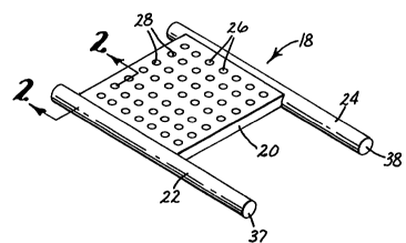
Figures 1-4, illustrated is a unitary heat exchanger 10
WO 95/14120 . .; l PCTIUS93/11424 --
2~
-12-
comprising a heat exchanger body 12, a first fluid
manifold 14, and a second fluid manifold 16. The first
and second manifolds 14 and 16, respectively, are
connectable to a fluid source or reservoir as part of a
5 first fluid circuit through which a heat transfer fluid
is circulated. The unitary heat exchanger 10 can be
used as a heat source or as a heat sink for heating or
cooling a component or other medium positioned adjacent
to or flowing next to the unitary heat exchanger 10.
The heat exchanger body 12 is integrally made with
and of the same material as the first and second
manifolds 14 and 16 by the method of the present
invention described below. Moreover, the heat
exchanger body 12 constitutes the primary heat
15 exchanger which supplies heat to or accepts heat from a
component or other medium. In the embodiment
illustrated in Figure 3, the heat exchanger body 12 is
generally planar, although many other shapes are
contemplated as emphasized below. Passages within the
20 heat exchanger body 12 also comprise parts of the first
fluid circuit through which a heat transfer fluid is
circulated as it passes between the first manifold 14
and the second manifold 16.
In order to define the passages within the heat
25 exchanger body 12, first manifold 14 and second
manifold 16, in accordance with the method of the
present invention, a sacrificial core 18, shown in
Figure 1, is used. The external shape of the
sacrificial core 18 is generally similar to the overall
30 shape of the unitary heat exchanger 10. More
particularly, the sacrificial core 18 includes a heat
exchanger body forming portion 20, a first manifold
forming portion 22, and a second manifold forming
portion 24. The external surfaces of the heat
35 exchanger body forming portion 20, first manifold
forming portion 22 and second manifold forming portion
24 define the interior surfaces of the passages defined
WO9S/14120 S66~ 1 PCT~S93/11424
within the heat exchanger body 12, first manifold 14
and second manifold 16, respectively.
The sacrificial core 18 can be formed as a single
unit, or may be made up of separate elements adhered,
-- 5 fused or otherwise fixed together. Specifically, the
sacrificial core 18 including body forming portion 20
and manifold forming portions 22 and 24 can be formed
as a unit by a molding process of the entire
sacrificial core or can be made separately and then
10 fixed together by melt fusing or with adhesive. For
example, the first and second manifold forming portions
22 and 24 can be formed together in one piece as part
of a larger supporting structure (i.e., U-shaped or
rectangular), and the body forming portion 20 can then
15 be positioned on and joined to the first and second
manifold forming portions 22 and 24 by melting and
fusing the components together at such joints.
Suitable materials used for the sacrificial core
18 include waxes, plastics and fusible metals or
20 alloys. Specifically, examples of suitable waxes
include "Machinable Wax" available from Freeman
Manufacturing and Supply Company of Cleveland, Ohio and
"Tuffy" injection wax available from Kerr Manufacturing
Company of Romulus, Michigan. An example of a suitable
25 plastic is a polyacetal sold by E. I. DuPont de Nemours
and Company of Wilmington, Delaware under the trademark
"DELRIN". Fusible or low melting point metals include
the fusible alloys sold under the trademark "INDALLOY"
sold by Indium Corporation of America of Utica, New
30 York, particularly "INDALLOY 255"and "INDALLOY 281".
It is understood that many other waxes, plastics, and
metals could be used provided that they can be melted,
dissolved or decomposed without substantially harming
the material of the heat exchanger formed about the
35 sacrificial core as described below.
In accordance with one example of a method for
making the sacrificial core 18, a piece of blue
"Machinable Wax" from Freeman Manufacturing and Supply
WO 95/14120 2 i7 ~ O ~ ~ ~`s ~ PCT/US93/11424 0
--14--
Company was formed into a thin wax sheet between heated
glass panes. The wax sheet was then cut into an
appropriate size to form the heat exchanger body
forming portion 20. The size, of course, depends on
5 the end use of the heat exchanger. Next, the cut sheet
portion was placed in proper location on an aluminum
mold which defines the first and second manifold
forming portions 22 and 24. The mold was clamped
together and molten green "Tuffy" wax from Kerr
10 Manufacturing Co. was poured into the mold until full.
Then, after cooling, the entire sacrificial core 18 was
removed from the mold including body forming portion 20
fused together with the first and second manifold
forming portions 22 and 24.
It is, however, understood that any suitable wax
or plastic or combinations and blends thereof could be
simply formed into the entire sacrificial core 18 by a
single molding step, such as by conventional injection
molding techniques. Moreover, when using a fusible
20 alloy, it is preferable to mold the fusible alloy into
the sacrificial core 18 by a single molding step.
Alternatively, the sacrificial core 18 could be made by
a machin;ng process, wherein a block of suitable wax,
plastic or fusible metal could be machined down to the
25 desired core shape.
Referring again to Figures 1 and 2, the heat
exchanger body forming portion 20 of the sacrificial
core 18 is further provided with a plurality of through
holes 26. The through holes 26 are defined by internal
30 surfaces 28 of the core material forming the body
forming portion 20. As seen in Figure 1, the through
holes 26 are arranged in accordance with a
predetermined pattern, the reason for which will be
apparent with the description of the formation of the
35 unitary heat exchanger 10 below. Furthermore, the
through holes 26 and thus the internal surfaces 28 can
be made by drilling or otherwise machining through the
body forming portion 20 after the formation of the
WO 95/14120 S66 ` PCT/US93/11424
--15--
sacrificial core 18 as described above. Alternately,
the through holes 26 can be formed during the formation
of the body forming portion 20 either before or during
formation of the first and second manifold forming
5 portions 22 and 24. In any case, to form the through
holes 26 during a molding step, the mold used for
forming the body forming portion 20 is provided with
elements having external surfaces that correspond to
the internal surfaces 28 on the body forming
10 portion 20.
After the sacrificial core 18 is fully formed, the
unitary heat exchanger 10 is formed about the
sacrificial core 18. Then, the sacrificial core 18 is
removed. In accordance with the present invention, the
15 unitary article 10 is formed by a deposition step.
Deposition is defined as the controlled formation of
material on an article from the ambient solution, gases
or mixtures thereof within which the article is
located. Deposition includes electrochemical, chemical
20 and physical techniques and the like. Chemical
deposition means t~chniques for depositing body forming
material as a result of a chemical reaction, such as by
chemical vapor deposition (CVD). Physical techniques
include deposition methods such as spraying or
25 sputtering techniques or the like. Preferably,
electrochemical plating is utilized.
Electrochemical plating is defined as the
deposition of a continuous layer of material onto an
article by the interaction in solution of a metal salt
30 and supplied electrons which are the reducing agent of
the metal salt. One type of electrochemical plating is
known as electroless plating within which the electrons
supplied for reduction of the metal salt are supplied
by a chemical reducing agent present in the solution.
35 Another type of electrochemical plating is known as
electrolytic plating, or more commonly as
electroplating, wherein the electrons used for
reduction of the metal salt are supplied by an external
WO95/14120 ~ PcT~S93/11424 -
~175~16~
-16-
source such as a battery, generator or other DC power
supply including rectifiers of AC current. In
electroplating, the object to be plated must have or be
provided with a conductive surface. Furthermore,
5 conventionally known pulse plating techni~ues can be
optionally used where periodic reversals of the current
flow direction can be controlled to enhance
electroplating of certain metals, particularly with
copper.
A major advantage of electroless plating is that
certain metals can be plated on properly prepared
non-conductors as well, as further described below.
The most common metals that can be deposited by
electroplating or by electroless plating are nickel,
15 copper, gold and silver; however, many other known
metals, alloys, compounds and composites are also known
to be capable of deposition by electrochemical plating.
The formation of a self-supporting structure by
electrochemical plating, such as the unitary heat
20 exchanger 10 of the present invention, is hereinafter
referred to as electroforming.
Referring again to Figures 3, 4A and 4B, the
unitary heat exchanger 10 is formed, preferably
electroformed, substantially completely about the
25 sacrificial core 18 so as to substantially envelope the
sacrificial core 18 and to form the unitary heat
exchanger 10 with a shape generally similar to the
shape of the sacrificial core 18. Moreover, the heat
exchanger body 12 is integrally formed at the same time
30 with the first and second manifolds 14 and 16, and of
the same material. Furthermore, the forming material
is also deposited on the internal surfaces 28 of the
body forming portion 20 of the sacrificial core 18.
The result of such deposition of forming material
35 within the through holes 26 is a plurality of posts 30
that integrally connect the upper plate 32 and the
lower plate 34 of the heat exch~nger body 12. The
number of posts 30 corresponds to the number of through
WO95/l4l20 , j PCT~593/llJ24
holes 26 defined by internal surfaces 28. This
formation of the posts 30 at the same time as the
- formation of the heat exchanger body 12 and first and
second manifolds 14 and 16 results in an integral
5 structure that exhibits a greatly improved strength and
which can accommodate substantially higher fluid
pressures than that of multi-component heat exchangers.
Furthermore, the number of and pattern of the posts 30
can be chosen for specific strength characteristics.
10When electrochemical deposition is used to
electroform the unitary heat exchanger lO, such
electrochemical deposition, particularly with
electroplating, may result in forming material being
deposited more rapidly at sharp edges of the
15 sacrificial core 18 than at other portions. Thus the
opposed corner edges 29 of internal surfaces 28 may
have a tendency to be electroplated faster than the
remainder of the internal surfaces 28 depending on the
rate of deposition. ~he result could be posts 30 which
20 are closed at the bottoms and tops thereof but which
are hollow in the center. It has been found that
slower rates of deposition reduce the possibility of
hollow posts. Moreover, the edges 29 can be chamfered
or rounded as shown in Figure 2 at 29' to reduce the
2~ formation of hollow posts 30 and to increase post
strength.
Another important advantage associated with the
posts 30 is that the posts 30 enhance heat transfer by
providing additional surface area with the heat
30 exchanger body 12 and by causing more turbulent fluid
flow within the heat exchanger body 12. Further in
this regard, it is also contemplated to increase
turbulent fluid flow to enhance heat transfer by
structuring the internal surfaces 33 and/or 35 of
35 plates 32 and 34. By structuring, it is meant the
formation of grooves, ridges or other structures
(regular or not) on one or both of surfaces 33 or 35
which will tend to break up the fluid flow between
woss/l4l20 PCT~S93/11424 -
Q ~ &
-18-
plates 32 and 34. In the same sense, the posts 30 can
be formed of other shapes than cylindrical or may be
provided on the surfaces thereof with structuring. In
any case, whether the structuring is provided on the
5 internal surfaces 33, 35 and/or the posts 30, such
structuring can be easily provided by forming
complimentary structures on the surfaces of the
sacrificial core 18. Specifically, such ridges,
grooves or other structures can be formed on the
10 surfaces of the body forming portion 20 or the internal
surfaces 28 thereof. Such formation may be done during
molding of the sacrificial core 18 or thereafter by a
machining process, or the like.
As mentioned above, the sacrificial core 18 may
15 comprise a wax, plastic, fusible alloy or the like. If
the method of deposition of forming material used to
form the unitary heat exchanger 10 is electroplating,
then it is necessary that the outer surface of the
sacrificial core 18 onto which the forming material is
20 to be deposited be conductive. In the case of using a
non-conductive wax or plastic sacrificial core, it is
first necessary to render the external surface thereof
conductive. One manner of rendering the external
surface conductive is to treat the surface to form a
25 thin conductive layer thereon. This is conventionally
done by applying a very thin layer of a conductor such
as silver on the external surface of those portions of
the sacrificial core 18 onto which deposition will take
place. Any of the known conventional layering or
30 coating techniques can be utilized to provide a thin
conductive layer including painting, spraying or an
initial use of electroless plating. Thereafter,
electroplating can be conducted as if the sacrificial
core 18 were totally metallic. If electroless plating
35 is to be utilized as the manner of forming the entire
unitary heat exchanger 10, then it may not be necessary
to first render conductive the sacrificial core 18.
Proper electroless plating may require certain surface
WO9S114120 a~ :r PCT~S93/11424
preparation steps, which are well known, and which may
vary depending on the metal to be deposited and the
core forming material. Typical steps include, in
order, treatment with an etchant, a neutralizer, a
5 catalyst, an accelerator and then the electroless metal
bath.
As shown in Figure 4B, the sacrificial core 18
including the body forming portion 20 and first
manifold forming portion 22 are coated with a
lO conductive layer 36 when it is necessary to render the
external surfaces thereof conductive for plating by the
electroplating method. In contrast, Figure 4A
represents the combination of the unitary heat
exchanger lO and the sacrificial core 18 without the
15 need for an additional conductive layer when
electroless plating is used as the manner of
electrochemical deposition or if the sacrificial core
18 comprises a conductive material such as a fusible
alloy, or if other deposition techniques are to be
20 used. As above, if electroless deposition is to be
conducted, other surface treatments may be required.
Although it is preferable that electrochemical
deposition be used to make the heat exchangers
according to the present invention, it is contemplated
25 that other deposition techn;ques could be used. For
example, some metals, such as nickel, are known to be
capable of deposition onto an article by chemical vapor
deposition (CVD) methods. Moreover, other non-metals
could be used and deposited by a CVD method if the
30 material is strong enough to withstand the fluid
pressures and heat of a specific application.
After the forming material is deposited onto the
sacrificial core 18 and the unitary heat exchanger lO
is formed, the sacrificial core 18 must be removed. In
35 order to prepare for the removal of the sacrificial
core 18, some access must be provided from external of
the shell forming the unitary heat exchanger lO to the
passages formed within the unitary heat exchanger lO by
WO9S/14120 PCT~S93111424 -
....
2 i7 ~6 -~20-
the sacrificial core 18. One manner to do this, as
shown in Figure 3, is to control the deposition of
forming material onto the sacrificial core 18 such that
at least a portion of one of the first or second
5 manifold forming portions 22 or 24 of the sacrificial
core 18 is not covered by the forming material. In
other words, at least a portion of one of the manifold
forming portions 22 or 24 remains free of forming
material after the deposition step is complete and the
10 unitary heat exchanger 10 is fully formed. As seen in
Figure 3, an end 38 of manifold forming portion 24 is
shown free of forming material.
This can be done in a variety of ways. If the
sacrificial core 18 is made of a non-conductive
15 material such as a wax or plastic and electroplating is
to be used as the deposition step, then by simply not
coating a portion of the manifold forming portion 22 or
24 with a conductive layer, such portion will remain
free of forming material. In the cases where the
20 sacrificial core 18 is conductive or rendered
conductive and electroplating is to be used or where
electroless deposition or another chemical or physical
deposition method is to be used on a conductive or non-
conductive sacrificial core 18, then it may be
25 desirable to positively treat such a portion of the
manifold forming portions 22 or 24 so as to prevent
deposition of forming material thereon. This can be
done by wrapping or otherwise coating such a portion
with a tape or coating of material that will prevent
30 the deposition of forming material thereon. When using
electroless deposition, it is necessary to wrap with a
tape or to coat that portion with any one of known
materials onto which electroless deposition does not
easily deposit. In the case of electroplating a
35 conductive sacrificial core 18, it is preferred to use
a non-conductive tape to provide the at least one
portion to which forming material is not deposited. It
is, however, contemplated that any other non-conductive
WO95/14120 PCT~S93/11424
~ ~ -21-
coating, paint or the like could be used instead.
Moreover, it is preferred that more than one access
- opening be provided by controlling the deposition so
that a plurality of sacrificial core portions remain
5 after deposition that are free of forming material.
More preferably, it is desirable that such portions
free of forming material be provided at both ends of
each of the manifold forming portions 22 and 24.
Another manner of providing the needed access
10 opening through the shell of the unitary heat exchanger
10 is also illustrated in Figure 3, which is used when
the manifold forming portions 22 and 24 including ends
thereof 37 and 38, respectively, are entirely covered
by forming material. The access opening is provided by
lS removing the forming material from at least one of, and
preferably all of, the ends 37 or 38. This removal can
be easily done by simply cutting away a portion of the
manifolds 14 or 16 (as illustrated in Figure 3 where a
portion of first manifold 14 is cut away) including the
20 ends 37 and/or 38. Other means for providing an access
anywhere along the first or second manifolds 14 or 16
such as grinding, drilling or the like are also
contemplated.
No matter how the access opening or openings are
25 provided through the shell of the unitary heat
exchanger 10, the step of removing the entire
sacrificial core 18 follows. The preferred manner of
removing the sacrificial core 18 is by heating the
unitary heat exchanger lO including the sacrificial
30 core 18 to a temperature above the melting point of the
sacrificial core 18 but below the melting point of the
forming material making the unitary heat exchanger 10.
The forming material of the unitary heat exchanger is
preferably nickel or copper. Thus, the choice of
35 materials for the sacrificial core 18 is dictated by
its melting temperature as compared to that of the
forming material of the unitary heat exchanger 10.
Waxes and plastics such as those noted above are in
WO95/14120 ~ PCT~S93/11424 ~
6~ t'~",' '
-22-
most cases suitable for such sacrificial core use.
Known low melting temperature metals and alloys, also
as noted above and known as fusible metals and alloys,
also work well.
To accomplish the removing step, the combination
of the unitary heat exchanger lO and sacrificial core
18 are preferably placed in a heated environment or
heat is directly applied to the unitary heat exchanger
lO. Furthermore, the access opening is preferably
lO provided in a position and held in that position so
that the flow of molten sacrificial core material under
the influence of gravity will completely drain all of
the sacrificial core forming material from within the
unitary heat exchanger lO. It is also contemplated
15 that one or more access openings could be connected to
a pressurized source or a vacuum to assist in the
removal of sacrificial core material.
Alternately, the sacrificial core 18 can be
removed by chemically dissolving the sacrificial core
20 18 in a solution. In that case, the sacrificial core
18 should be comprised of a material which is easily
dissolved in solution that will not substantially harm
the forming material of the unitary heat exchanger lO.
In a similar manner, the material of the sacrificial
25 core 18 can be a material which decomposes as a result
of the application of a controlling affect. For
example, when the plastic material known as DELRIN,
discussed above, is used in forming the sacrificial
core 18, the application of heat as the controlling
30 affect causes such material to decompose to
formaldehyde which escapes as a gas.
Although the deposition step of forming material
to form the unitary heat exchanger lO can be any known
deposition t~chnique in accordance with the above, a
35 specific example of a suitable preferred electroplating
technique is described as follows. In one example, the
sacrificial core 18 was produced, as above, out of a
combination of blue "Machinable Wax" and green "Tuffy"
~ WO95/14120 21 7 5 0 6 ~ PCT~S93111424
-23-
wax. Then, holes were drilled in the heat exchanger
body forming portion 20 of the sacrificial core 18 with
hole diameters ranging between 0.015 inch and 0.030
inch at a non-staggered spacing of between 0.05 inch
5 and 0.20 inch. Next, the sacrificial core 18 was
mounted on a brass turning rod for plating. Then, a
silver coating was provided over the entire sacrificial
core 18 by electroless deposition for rendering the
entire sacrificial core 18 conductive for
10 electroplating. A silver paint was used to touch up
the sacrificial core 18, particularly at intersection
points. After that, the manifold forming portions 22
and 24 were masked at their ends 37 and 38 with a
non-conductive tape so that plating would not occur on
15 those ends.
Thereafter, the acrificial core 18 and brass
turning rod were imme~sed in a nickel sulfamate bath
(not shown) containing 16 ounces/gallon of nickel; 0.5
ounces/gallon of nickel bromide; and 4.0 ounces/gallon
20 of boric acid. Also, 0.1 ounces/gallon of a
surfactant, namely "DUPONAL ME" available from E. I.
DuPont de Nemours and Company of Wilmington, Delaware,
was added to the bath to prevent H2 bubbles from
sticking to the surfaces of the sacrificial core 18 and
25 to thereby minimize gas pitting. The remainder of the
plating bath was filled with distilled water. A
quantity of S-nickel anode pellets were contained
within a titanium basket which was suspended in the
plating bath. A woven polyproplyene bag was provided
30 surrounding the titanium basket within the plating bath
for trapping particulates. The plating bath was
continuously filtered through a 5 micron filter. The
temperature of the bath was maintained at 90 F., and a
pH of 4.0 was maintained in the plating bath solution.
35 A current density of 10 amps per square foot was
applied to the sacrificial core 18 for 48 hours with
the sacrificial core 18 and brass turning rod
continuously rotated at 6 rpm to enhance uniformity of
,
WO 95/14120 2 ~ ~ 0 6 ~ ` PCTIUS93/11424 --
-24-
deposition. The voltage applied to the sacrificial
core 18 is a function of the conductivity of the bath
to produce the desired amps. Upon removal, a unitary
heat exchanger 10 with integral heat exchanger body 12
5 and first and second manifolds 14 and 16 was produced
of nickel having an average thickness of about 24 mils
(.610 mm). As a general rule, at 20 amps per square
foot, the nickel is deposited at a rate of
approximately 1 mil/hr (.0254mm/hr). At 10 amps per
10 square foot, the nickel is deposited at an approximate
rate of .5 mil/hr (.0127mm/hr). Slower formation
generally increases strength and improves uniformity of
wall thicknesses and posts 30. Moreover, there is less
of a tendency for the posts 30 to be formed hollow, as
15 discussed above, when 10 amps per square foot is
applied to the sacrificial core 18. Next, the
sacrificial core 18 was removed by applying heat
directly to the unitary heat exchanger 10 with the
access openings that were provided by the masked ends
20 of manifold forming portions 22 and 24 arranged
downwardly so that as the sacrificial core 18 was
melted, the wax material flowed out of the shell of the
unitary heat exchanger 10. As a result, clean passages
were provided within the heat exchanger body 12 and
25 first and second manifolds 14 and 16. Moreover, a
plurality of posts 30 were formed at each of the
locations of the through holes 26 according to the hole
diameter and spacing and pattern of through holes 26
drilled within the heat exchanger body forming portion
30 20 of the sacrificial core 18.
Furthermore, the formed unitary heat exchanger 10
exhibits a greatly improved structurally sound integral
unit with the passage of the heat exchanger body 12 in
fluidic communication with both the first and second
35 manifolds 14 and 16 without leakage problems.
Moreover, the structural integrity is greatly improved
by the pattern of posts 30 which strengthen the heat
exchanger body 12. This strength is particularly
WO95/14120 ~6 PCT~S93/11424
-25-
important in that the heat exchanger body 12 can handle
heat exchange fluids at relatively high pressures with
a minimum of plate deflection. Minimizing plate
deflection is critical when using the heat exchanger
5 adjacent to certain components, such as electronic
circuitry since deflection could adversely affect the
circuitry and could reduce the overall surface contact
between the unitary heat exchanger lO and the
component.
A further advantage of such posts 30 is that they
improve heat transfer. The posts 30 not only provide
additional surface area for contact with the circulated
heat exchange fluid, but also cause more turbulent
fluid flow of the heat exchange fluid through the heat
15 exchanger body which breaks up boundary layers and
thereby enhances heat transfer.
It is also noted, that throughout the
~llustrations of the Figures, the height of the heat
exchanger body 12 with respect to the diameter, in
20 cross-section, of the first and second manifolds 14 and
16 is greatly exaggerated for clarity. That is not to
say that the heat exchanger lO cannot be formed with
such a dimensional ratio, but that it is preferable to
keep the thickness of the heat exchanger body 12
25 relatively thin as compared to the size of the passages
within the manifolds so that a relatively large amount
of heat exchange fluid can be readily available to flow
through the heat exchanger body 12 and to easily
position the heat exchanger body 12 adjacent to a
30 component or circuitry to be cooled. Further in this
regard, the heat exchanger body 12 can advantageously
be positioned off center of the plane connecting the
axis lines of the first and second manifolds 14 and 16
so that the heat exchanger body 12 can be more easily
35 positioned immediately adjacent to a component.
In operation of the unitary heat exchanger lO as a
heat exchanger, the first manifold 14 is preferably
connected to a supply rail (not shown) of heat exchange
WO95/14120 t ~ PCT~S93/11~24 -
I 6~
-26-
fluid. The second manifold 16 is also preferably
connected to a rail further connected to a drain line
(not shown) which is associated with a reservoir (not
shown). Heat exchange fluid is conventionally supplied
5 from a source including a pressurizing means such as a
pump (not shown) which maintains a sufficient fluid
pressure within the supply rail and first manifold 14.
The heat exchange fluid then flows through the heat
exchanger body 12 at a rate sufficient to heat or cool
lO whatever component the heat exchanger lO is provided
adjacent to, and the heat exchange coolant fluid then
exits through second manifold 16 and eventually back to
a supply reservoir. If the component is to be cooled
by the heat exchanger lO, then it is also necessary to
15 provide a cooling means (not shown) for the heat
exchange fluid before the fluid enters the first
manifold 14. If the component is to be heated, then a
heating means (not shown) must be similarly
incorporated.
Referring now to Figures 5-8, another embodiment
of the present invention is illustrated as a unitary
heat exchanger 40 which is formed in substantially the
same manner as the unitary heat exchanger lO described
above. Additionally, as shown in Figure 5, the unitary
25 heat exchanger 40 has an electronic component 42 fixed
adjacent to the heat exchanger body 44, and more
specifically against a substantially planar surface 46
thereof. The surface 46 may be conventionally machined
flat to better contact such component 42 since
30 electroforming may result in some surface unevenness.
Such a finishing step may be done in any case,
particularly where the unitary heat exchanger lO is to
be placed adjacent to a component. The heat exchanger
body 44 is integrally formed with a first manifold 48
35 and a second manifold 50 in accordance with the method
described above with respect to Figures 1-4.
In order to form the unitary heat exchanger 40 so
as to accommodate the mounting of the electronic
WO95114120 21 7SD B~ PCT~S93/11424
-27-
component 42 against surface 46, a sacrificial core 52
is fabricated as shown in Figure 6. As above, the
sacrificial core 52 can be made from a wax, plastic,
fusible alloy, or the like. The difference between the
5 sacrificial core 52 of the second embodiment as
compared to the sacrificial core 18 of the first
embodiment is that the sacrificial core 52 is
additionally formed with a plurality of large through
holes 54 defined by internal surfaces 56. The large
lO through holes 54 correspond to the mounting position of
the electronic component 42 as illustrated in dotted
lines, and are provided for accommodating mounting
elements such as screws or bolts 58 and lead wires of
the component 42.
The large holes 54 are dimensioned to be
sufficiently large so that during the deposition step
of forming material to make the shell of unitary heat
exchanger 40, apertures 60 remain through the unitary
heat exchanger 40 after deposition is complete. In
20 other words, deposition is ceased when the apertures 60
sill remain. Moreover, at the same time, posts 62 are
formed within the smaller through holes 64 defined by
internal surfaces 66. Preferably, the posts 62 are
closed. Thus, deposition is stopped when the closed
25 posts 62 are formed but while apertures 60 remain. The
smaller through holes 64 are arranged in a
predetermined pattern to provide strength to the heat
exchanger body 44 similarly as in the first embodiment.
The apertures 60, however, not only provide structural
30 support by the circumferential walls 68 thereof, but
also define a passage through which the screws or bolts
58 and lead wires 59 can pass. The apertures 60 are
formed during the deposition step by controlling the
thickness of deposited forming material on the
35 sacrificial core 52 such that the posts 62 are
adequately formed while leaving apertures 60.
Furthermore, as above, the fabrication is
completed by providing at least one access opening
WO9~/14120 i b ~ PCT~S93/11424 -
-28-
through the shell of the unitary heat exchanger 40 and
thereafter removing the sacrificial core 52 by melting,
dissolving, decomposing or otherwise so as to leave
open passages in fluidic communication between the
5 first manifold 48, heat exchanger body 44 and second
manifold 50.
As illustrated in Figure 8, the passages within
the first manifold 48 and heat exchanger body 44 are in
fluidic communication with one another. A plurality of
lO closed posts 62 are shown connecting an upper plate 70
to a lower plate 72 both of the heat exchanger body 44.
The external surface of the upper plate 70 defines the
surface 46 against which the electronic component 42 is
located. Screws or bolts 58 extend through a mounting
15 plate 43 of the electronic component 42, upper plate
70, one of the apertures 60 defined by a
circumferential wall 68, and lower plate 72. A
conventional nut or the like is provided on the screw
or bolt 58 for securing component 42 in place.
In the illustrated embodiment, two of the
apertures 60 are utilized for the passage of screws or
bolts 58 so as to mount the component 42 to the heat
exchanger body 44 while the other two are used for the
passage of lead wires 59 therethrough. In use, heat
25 generated by the electronic component 42 conducts into
the heat exchanger body 44 wherein a fluid coolant is
circulated for absorbing and transferring away the
heat. Any suitable coolant fluid can be used
including, but not limited to, air, water, or refrig-
30 erants, such as "Fluorinert" which is a trademarkedfluorochemical coolant marketed by Minnesota Mining and
Manufacturing Company of St. Paul, Minnesota. It is
also understood that the shape and locations of the
apertures 60 through the heat exchanger body 44 can be
35 designed in accordance with the needs of a specific
electronic component. Moreover, more or less apertures
60 can be provided as necessary for the specific
component or components.
~ WO9S/14120 21 7506C PCT~S93/11424
-29-
Referring now to Figures 9-ll, yet another
embodiment of a unitary heat exchanger 74 is
illustrated. This third embodiment is substantially
similar to that described above with respect to Figures
~ 5 5-8, except that apertures 76 are formed in a
predetermined pattern through the heat exchanger body
78 of the unitary heat exchanger 74. As seen in Figure
9, a sacrificial core 80 is formed having a heat
exchanger body forming portion 82 connected between a
lO first manifold forming portion 84 and a second manifold
forming portion 86. Large through holes 88 are
provided by drilling or another forming technique
through the heat exchanger body forming portion 82
defining internal surfaces 90. During the deposition
15 step, such as electropla~ing, the large through holes
88 allow forming materia~ to be deposited on the
internal surfaces 90 thereof thereby making cylindrical
walls 92 connecting between upper and lower plates 94
and 96, respectively, of the heat exchanger body 78.
20 The cylindrical walls 92 define apertures 76 passing
through heat exchanger body 78. of course, apertures
can be made other than circular and the walls defining
the apertures could likewise be other than cylindrical.
The aperture shape and the walls defining the apertures
25 can be selectively controlled by the shape of the
internal surfaces 90 defining the through holes 88.
It is also contemplated to further provide a
pattern of smaller through holes 98 through the heat
exchanger body forming portion 82 of the sacrificial
30 core 80 in combination with the large through holes 88.
These smaller through holes 98 are used to make
additional posts lO0 for increased structural
integrity. It is, however, understood that the
cylindrical walls 92 may be sufficient for many
35 applications for providing adequate structural rigidity
without additional posts lO0. In such a case, only the
larger through holes 88 would need be provided through
the heat exchanger body forming portion 82 of the
WO9S/14120 6~ PCT~S93/11424 -
-30-
sacrificial core 80. Likewise, as above, the
dimensions of the large through holes 88 and thus of
the apertures 76 are chosen so that when deposition,
such as electroplating, takes place the thickness of
5 material deposited is controlled so that the apertures
76 remain. The size of the apertures 76 are dependent
on the specific application of the apertured unitary
heat exchanger 74. Different size apertures can be
formed in combination for a specific purpose.
An application of the unitary heat exchanger 74 is
as a fluid-to-fluid heat exchanger where a first fluid
is circulated through the unitary heat exchanger 74 by
way of manifolds and the heat exchanger body 78 while a
second fluid medium is passed in one direction through
15 the plurality of apertures 76 formed through the heat
exchanger body 78. The fluid circulated within heat
exchanger body 78 can be used to cool or heat the fluid
medium passing through the apertures 76. One specific
application of such a fluid-to-fluid heat exchanger is
20 utilized in the system shown and described in U.S.
Patent Nos. 4,295,282 to Fox, 4,480,393 to Flink et al.
and 4,539,816 to Fox, each commonly owned by the
assignee of the present invention, and fully
incorporated herein by reference. Generally, such a
25 heat exchanger is useful in the described recovery
system and apparatus for recovering condensable liquid
from a gaseous environment.
Referring now to Figures 12-14, yet another type
of unitary heat exchanger is illustrated which can be
30 fabricated in accordance with the present invention. A
sacrificial core 102, shown in Figure 12, is used for
making a unitary heat exchanger having a plurality of
discrete microchannels connected between manifolds as
opposed to a common channel between parallel plates as
35 in the embodiments described above. The sacrificial
core 102 comprises a first manifold forming portion
104, a second manifold forming portion 106 and a
plurality of discrete microchannel body forming
WO95114120 7~ PCT~S93/l1424
portions 108 which together comprise the body forming
portion 110 of the sacrificial core 102. As also seen
in Figure 12, the first and second manifold forming
portions 104 and 106 are preferably joined by a
~ 5 connecting section 112 for ease in molding of the
sacrificial core 102 and to add structural strength to
the sacrificial core 102 before the forming material is
deposited thereon since the discrete microchannel body
forming portions 108 are very fragile as compared to
10 the plate-like body forming structures of the
embodiments above. of course, such a connecting
section can just as easily and beneficially be used
with the sacrificial cores of the above described
embodiments. In any case, the connecting section 112
15 is preferably treated or masked so as not to be
deposited with forming material during the deposition
step.
Figure 13A illustrates one possible cross-section
taken along 13-13 in Figure 12, wherein the discrete
20 microchannel body forming portions 108 have circular
cross-sections. Figure 13B is a view similar to that
of Figure 13A except that the cross-sectional shape of
each of the discrete microchannel body forming portions
108' is hexagonal. Figure 13C illustrates yet another
25 possible cross-sectional configuration of the discrete
microchannel body forming portions 108'' as a slightly
rounded tetrahedron. It is understood that many
different cross-sectional variations are contemplated
and can be used in accordance with the present
30 invention with the above specific examples illustrating
only a few of the possibilities. The cross-sectional
shapes being limited primarily by the ability to mold
the sacrificial core. However, the deposition
technique may also otherwise limit such shapes.
3S Moreover, with this embodiment as well as those
described above, the flow transition from the manifold
to microchannelled body can be advantageously contoured
to minimize pressure drop. Furthermore, the use of the
WO 95/14120 PCTIUS93/11424
~; ~
-32-
process of the present invention does not limit the
channels or manifolds to straight lines or constant
cross-sections. A variable cross-sectional channel
could be used to increase or decrease heat transfer
5 coefficients as the temperature difference decrease or
increases, or the cross-sections of the microchannels
can be designed to concentrate heat transfer at
specific areas of heat generation while reducing fluid
pressure drop.
Referring now to Figures 14A, 14B and 14C, the
discrete microchannel body forming portions 108, 108'
and 108'' shown in Figures 13A, 13B and 13C,
respectively, are deposited with forming material to
provide a heat exchanger body 114,114' or 114'' of a
15 unitary heat exchanger having microchannel passages
116, 116' or 116'' with cross-sectional shapes
determined by the cross-sections of the discrete
microchannel body forming portions 108, 108' or 108''.
Note that as the heat exchanger body 114 is formed by
20 deposition about the microchannel body forming portions
108, 108' or 108'', the forming material may eventually
grow together as the deposited layer is thickened to
make a unitary heat exchanger body 114, 114' or 114''
encompassing all of the discrete microchannel passages
25 116, 116' or 116''. Moreover, deposition can be
conducted long enough to build up such a unitary heat
exchanger body having a block appearance.
Additionally, the surfaces of the body thereof can be
machined or otherwise finished to provide substantially
30 planar surfaces. Otherwise, the deposition could be
controlled as well as the spacing between the
microchannel body forming portions 108 so that after
deposition the heat exchanger body comprises spaced
discrete body portions containing microchannels without
35 connection along their longitudinally edges. Such an
open spaced heat exchanger body would be useful in a
fluid-to-fluid heat exchange environment.
W095/l4l20 ~ 6, PCT/U593/ll4~4
--33--
In a similar sense as that shown in Figures 12-14,
the sacrificial core 102 may include discrete
microchannel forming portions 108 that comprise
filaments, yarns, wires or the like that can be melted,
5 dissolved or decomposed in accordance with the method
of the present invention. Such filaments could be
strong between the manifold forming portions 104 and
106. Moreover, the filaments can be structured or
twisted to produce desired flow characteristics.
Another configuration for a sacrificial core 118
is illustrated in Figure 15. This sacrificial core 118
will produce a truncated conical heat exchanger of the
type similar to that of the Figures 1-4, 5-8 and 9-11
embodiments in that the heat exchanger would include a
15 heat exchanger body comprising two spaced plates
separated from one another through which heat exchanger
fluid passes. Preferably also, such a sacrificial core
118 is also provided with a pattern of through holes
120 defined by internal surfaces 122. In the same
20 sense as the aforementioned embodiments, during the
deposition step, the forming material fills the through
holes 120 to form posts connected between the spaced
plates of the heat exchanger body.
It is further contemplated that a manifold forming
25 portion could be provided with the sacrificial core 118
to extend longitudinally, circumferentially along one
edge or an intermediate portion, or may be provided as
a plate at one of the sides. This embodiment
exemplifies the many possibilities for shapes of heat
30 exchangers which are to be customized for a specific
use. Such advantageously allows heat exchangers to be
designed to fit very nearly against components of
complex geometries or to be used in environments
requiring such complex shapes.
For example, the heat exchanger body could be
formed to include stepped portions which correspond to
and follow the levels of a variety of components, such
as electronic components of different sizes mounted on
wo9sll4l2o PCT~S93/11424 ~
i'O ~;~
-34-
a circuit board. Thus, each portion could intimately
contact a component of a different size.
Thus, it is clear that many different geometries
are possible in the formation of a heat exchanger in
5 accordance with the present invention, such geometries
being primarily limited by the ability to form a
sacrificial core in that way. Furthermore, manifolds
can be integrally made with such complex geometries and
can also be custom made for a specific situation. That
lO is, one or more manifolds can be provided and the
positions thereof on the sacrificial core can be formed
as needed. For instance, even with a substantially
planar type heat exchanger body, as in Figure 3, the
manifold could be provided centrally of the heat
15 exchanger body, along one edge, two edges or more, or a
combination thereof.
Additionally, the materials used to form the
unitary heat exchanger can comprise any material which
can be deposited about the sacrificial core, which is
20 strong enough to handle the pressures associated with
the heat exchanger, and which is capable of maintaining
its structural integrity during the step of removing
the sacrificial core by melting, dissolving,
decomposition, or the like. Preferable materials
25 include nickel and copper which are easily
electrochemically applied by either electroless plating
or electroplating as described above and have good
thermal conductivity properties.
It is also contemplated to apply forming materials
30 in layers which can be chosen depending on the
circumstances and environment of the application for a
specific heat exchanger. For example, it might be
desirable to first deposit a layer of nickel onto the
sacrificial core because of its strength and corrosion
35 resistant properties with certain fluids, and then to
deposit copper as the remainder of the body to take
advantage of its better heat conductivity. Such
WO95114120 ~ ~~6 PCT~S93/11424
-35-
controlled deposition can easily be accomplished by
electroplating.
Thus, the scope of the present invention should
not be limited to the structures described by the
5 plural embodiments of this application, but only by the
limitations of the appended claims.