Note: Descriptions are shown in the official language in which they were submitted.
217~106
Joint for Variable Wall Thickness Pipe
Field of the Invention
The present invention relates to joints formed between
pipe sections. More particularly, the present invention relates
to joints formed between plastic pipe sections particularly
useful in microtunneling, sliplining or pipe bursting
applications, wherein the pipe sections have a variable wall
thickness.
Backqround of the Invention
Pipes that contain and transport water are used in
numerous applications, which are generally divided into the broad
categories of non-pressure and pressure applications. The
present invention is useful on pipes suitable for both non-
pressure and pressure applications and is particularly useful in
sewage and drain pipes. Other applications for the present
invention are also contemplated, such as conduit sections used
for housing telecommunications cable, fiber optics cable and
electrical wire or cable.
Pipe can be installed in a number of ways, one of which
is the traditional pipe laying tec~nique of simply digging a
trench and then placing the pipe sections in the trench,
assembling the sections into a pipeline and then covering the
pipeline. There are also trenchless pipe installation methods
known as microtunneling, sliplining and pipe bursting, which are
described below. The present invention can be used in
2 1 75 1 06
traditional applications and is particularly useful in trenchless
applications.
Microtunneling describes a process in which a vertical
access shaft is excavated to the pipe's starting grade. The term
starting grade means the level, or depth, at which the pipe will
be installed. A second vertical access shaft is constructed at
the ending location for the pipeline, the pipeline therefore
being erected between the two vertical shafts. A microtunneling
machine, which is usually a remotely controlled, steerable,
boring machine having a cutter head at one end, is lowered into
the first access shaft. The microtunneling machine bores or cuts
through the wall of the shaft and the cutter head drills a tunnel
through the soil towards the second access shaft. The soil that
is displaced by the cutter head is removed by either an auger
system, by which the soil is me~hAnically moved from the hole, or
a slurry system, which uses water to flush the loose soil from
the hole.
Before the entire microtunneling machine exits the
access shaft and enters the tunnel, a pipe section is attached to
the rear of the machine. Axial compressive force, or pressure,
directed along the longitudinal axis of the pipe section, is
applied to the end of the pipe section opposite the machine.
This force pushes the machine forward, with the pipe section
attached, into the tunnel towards the second shaft. A second
pipe section is then attached to the first, then a third is
attached to the second and so on. This process of adding
additional pipe and pushing the machine forward continues until
VOU~l~1~1~1 2
2 1 7i 1 06
the machine enters the second access shaft. At that point, an
entire length of pipe, consisting of a plurality of pipe
sections, is formed between the access shaft and the second
shaft. The machine is then disconnected from the pipe and the
pipeline is complete.
During the tunneling process, the machine is advanced
forward by pushing against the end of the last pipe section
attached and transmitting axial compressive force through the
connected pipe sections. Therefore, the pipe sections must be
joined in a manner so that a significant amount of axial
compressive force can be transmitted through the joints without
buckling, or otherwise damaging the joints or the pipe sections.
Furthermore, the tunnel formed by the microtunneling machine is
preferably just slightly larger than the diameter of the pipe
because the larger the diameter of the tunnel, the greater the
chance that the tunnel will collapse. If the pipe joints include
sections that project outward from the diameter of the pipe wall,
a larger tunnel must be bored to accommodate the pipe joints and
there is a greater chance that the tunnel will collapse.
Therefore, it is important that the pipeline have a smooth outer
surface.
Sliplining is a method of rehabilitating deteriorated
pipelines by inserting a new, small diameter pipe, called a
slipliner pipe, inside of an existing large-diameter pipe. When
sliplining, an access pit is dug to an existing pipeline; the
access pit being slightly longer than the length of one section
of the slipliner pipe. The top half of the section of existing
VOU~Xl~1~1~1 3
2 1 7 5 1 0~
pipe exposed at the bottom of the access pit is removed leaving
the bottom half which is known as a pipe cradle. A slipliner
pipe section is then placed inside the pipe cradle and is pushed
into the existing pipe, parallel to the longitudinal axis of the
existing pipe. A second slipliner pipe section is then lowered
into the pipe cradle and joined to the first section. The second
pipe section is then pushed into the existing pipe causing the
first pipe section to advance further into the existing pipeline.
Additional pieces of pipe are joined and the assembled pipe is
advanced until the existing pipeline is completely sliplined or
until the next access pit is reached. When the sliplining is
completed, grout or other sealing material is pumped into the gap
between the existing pipe and the new pipe along the entire
length of existing pipe that was sliplined.
Often, the existing pipe to be sliplined is broken and
dilapidated. The existing pipe's joints are sometimes separated
and pieces of debris or sections of the existing pipe extend into
the pipe cavity creating obstructions. Furthermore, if slipliner
pipeline has flared, or wide, joints, the pipeline inserted into
the existing pipe will have a relatively small diameter as
compared to the existing pipe and therefore may not be capable of
transporting a large enough volume of liquid. Therefore, it is
important that a slipliner pipe have a smooth outer surface.
Additionally, slipliner pipe sections also must be capable of
efficiently transferring an axial compressive force from one pipe
section to another.
VOU~l~1~l~l 4
21 7Jl C6
Pipe bursting is another method of pipeline
rehabilitation in which the existing pipe is replaced by a pipe
having a diameter equal to or larger than the existing pipe. In
this method, access is first gained to an existing pipe through a
manhole or access pit. A small diameter steel pipe is inserted
through the existing pipeline to a second access location. A
pipe bursting head, which is generally a solid metal cone, is
then attached to the steel pipe at the second access pit. The
steel pipe with the pipe bursting head attached is then retracted
towards the first access location by pulling the pipe. As the
bursting head is pulled through the existing pipe, the existing
pipe bursts into pieces that are displaced into the soil. A new
pipe is pulled h~hin~ the pipe bursting head and creates a new
pipeline. Pipe bursting creates numerous snags or obstructions,
which are usually pieces of broken existing pipe. Therefore, it
is important that the outer surface of the new pipe be smooth and
have no projections.
When forming a length of pipe to be used in the above-
described applications, several pipe sections are generally
mated, or joined, in an end-to-end relationship and the
connection between the mated, or joined, pipe sections is
referred to as a joint. Many types of pipe joints are disclosed
in the prior art.
United States Letters Patent No. 2,032,492 to Nathan
discloses a pipe joint assembly particularly useful for terracota
and ceramic pipes, wherein the pipe is molded and includes a
first end having a larger diameter than the second end. When two
VOUU~l~1~1~1 5
2 1 7 5 1 ~6
pipes are joined, an annular flexible gasket is placed on the
smaller diameter end of the first pipe and this end, including
the gasket, is inserted into the large diameter end of the second
pipe thereby forming a waterproof joint.
United States Letters Patent No. 4,565,381 to Joelson
discloses a concrete pipe wherein one end of the concrete pipe
has a tongue element ext~n~ing about the annular periphery
thereof and a flexible, stepped sealing element is attached to
the tongue. The second end of the pipe has a groove element
having a stepped sealing surface. The stepped sealing surface of
a first pipe section is joined with the tongue on a second pipe
section, whereby it seals against the stepped flexible seal.
United States Letters Patent No. 3,998,478 to Zopfi
discloses a sealing joint construction, including a gasket,
specifically for use with plastic pipes. The joint is formed by
inserting a spigot (i.e., a narrow) end of a first pipe section
into a bell (i.e., a flared) end of a second pipe section.
Preferably, the bell end is "double belled" meaning that it has a
narrow diameter bell section and a wider diameter bell section.
The spigot end of one pipe section is received in the narrower
bell portion of a second pipe section and part of the barrel,
i.e., the main body of the pipe, of the first pipe section
adjacent the spigot end is received in the wider bell portion of
the second pipe section. The outer end of the second pipe
section, which is formed adjacent the wider bell portion, is
wider than the barrel of the first pipe. Hence, an annular
groove is defined between the inner wall of the outer end of the
VOU~l~1~1~1 6
21 751 06
second pipe section and the outer wall of the barrel and a
flexible gasket is disposed in the groove to form a water-tight
seal.
United States Letters Patent No. 4,796,669 to St. Onge
discloses a method for relining pipeline with interconnectable
plastic pipe sections. The plastic pipe sections are joined by
either: 1) threading the end of one pipe into the end of another
pipe, 2) using a buttress-type thread to interlock one end of one
pipe to the opposite end of the second pipe, 3) forming two
opposed, angular members, respectively, on either end of the
pipe, the mating ends of two pipe sections sliding together and
snap-fitting into position, or 4) joining the pipe sections by
means of lap-joint members formed within the pipe walls and then
preferably taping the outer periphery of the joint.
The prior-art structures encounter problems when used
with a pipe having a variable wall thickness, especially if the
pipe is used in microtunneling, slipjoining or pipe bursting
applications. First, as previously described, it is advantageous
to form a pipe consisting of pipe sections wherein the pipe has a
smooth outer surface. This requirement eliminates the use of
external collar joints and most bell and spigot joints, which
usually have a section protruding from the outer surface of the
pipe. Furthermore, even joints formed within the walls of the
mated pipe sections, such as lap joints, do not provide a smooth
outer surface if formed in a variable thickness wall.
Second, the pipe sections must be joined so that a
significant amount of axial compressive force can be applied to
VOU~l~1~1~1 7
21 751 ~6
the end of one pipe section and be transmitted through the joints
to the other pipe sections in such a manner that the joints do
not flex, buckle or telescope; the term telescoping meaning that
the end of one pipe section is forced inside of the body of
another pipe to which it is joined. This requirement eliminates
the use of most joints formed within the walls of mated pipe
sections because the application of a significant axial
compressive force will cause the joints to deform or separate.
Even when a st~n~rd lap joint is used, if the pipe sections have
a variable wall thickness, the mating surfaces of the lap joints
do not align properly because of the variation in wall thickness.
This can cause one wall to bear the entire load which may cause
the wall to deform and the joint to fail.
Finally, a constant-width gap between the lap joint
members of the first pipe section and second pipe section must be
maintained so that a gasket may be inserted to form a water-tight
seal. Until this time, when joint profiles were formed in pipe
sections having variable width walls, the profile dimensions
varied as the thickness of the wall varied. Therefore, the
profile formed in one pipe section rarely, if ever, properly
aligned and mated with the profile formed in another pipe
section. If a gap was created by the joining of two pipe
sections, its dimensions varied according to the variations in
the respective wall thicknesses of the pipe sections that were
joined. As it will be understood, if the gap into which the
gasket, or sealing member, is retained is too wide, the gasket
V01~02Q D~ ~Ql!~5.1 8
2 1 7 5 1 J 6
will not form an adequate seal. If the gap is too narrow, the
fit is too snug and the pipe sections cannot be joined.
Summary of the Invention
The present invention solves these and other problems
by providing a pipe section, preferably being made from solid
plastic such as polyvinyl chloride ("PVC"), having a variable
wall thickness. The ends of the pipe section are formed so that
they can be joined with a mating end on another pipe section in
order to form a force-transmitting joint having a uniform-width
sealing gap and a smooth outer surface.
The invention comprises a pipe section comprised of an
annular pipe wall of variable thickness having an outer surface
and an inner surface, and a first end and a second end. A first
joint member is formed at the first end of the pipe section and
comprises a first support surface formed adjacent the outer
surface and a sealing leg formed adjacent the inner surface.
Importantly, the first support surface has a constant width, or
thickness. The sealing leg has a variable thickness equal to the
variable thickness of the pipe wall minus the constant width of
the first support surface. A sealing member is affixed about the
periphery of the sealing leg.
A second joint member is formed at the second end of
the pipe section and comprises a second support surface formed
adjacent the outer surface, wherein the second support surface
has a constant width that is less than the width of the first
VOU~ D~: 16Z19S.1 9
21 751 06
support surface. A recess, having a sealing wall and a variable
width is formed adjacent the outer surface.
When two pipe sections are joined, the first joint
member of a first pipe section aligns with and is received by the
second joint member of a second pipe section. Preferably, the
sealing leg is shorter than the recess and is retained within the
recess. The first support surface and second support surface
then align in a force-transmitting relationship. Because the
first support surface and second support surface have constant
widths, a uniform or constant-width gap is formed between the
sealing leg and the sealing wall of the recess, the sealing
member being retained therein. Finally, the outer surfaces of
the first pipe section and second pipe section align to form a
smooth surface across the joint.
In another embodiment of the invention, a joint is
provided for joining two sections of pipe. The joint comprises a
first joint member having a first annular wall comprising a first
outer surface and a first inner surface. A first support surface
is formed adjacent the first outer surface, the first support
surface having a constant width. A sealing leg is formed
adjacent the first inner surface and has a variable width. A
sealing member is positioned about the annular periphery of the
sealing leg.
The joint further comprises a second joint member
joined to the first joint member, the second joint member
comprising a second annular wall of variable thickness having a
second outer surface and a second inner surface. A second
VOUI~Q D~ 1621ff.1 1 0
21 1S1 ~6
support surface having a constant width is formed adjacent the
second outer surface and engages the first annul ar support
surface in a force-transmitting relationship. A recess is formed
adjacent the second inner surface, wherein the recess has a
sealing wall and a variable width. The sealing leg is positioned
at least partially within the recess, a constant-width gap being
defined between the leg and the sealing wall of the recess. The
sealing member is disposed within the gap to form a fluid-tight
seal.
It is therefore an object of the present invention to
provide a pipe section that can be assembled with other pipe
sections to form a pipeline.
It is another object of the invention to provide a pipe
that can be assembled with other pipe sections to form a pipeline
used for microtunneling, sliplining or pipe bursting
applications.
It is another object of the present invention to
provide pipe sections that can be joined so as to form a smooth
outer surface on a pipeline consisting of several pipe sections.
It is another object of the present invention to
provide pipe sections wherein axially applied compressive force
can be transmitted from one pipe section to another without
disturbing or deforming the joints between pipe sections.
It is another object of the present invention to
provide a pipe section as described above that connects to
another pipe section to form a joint therebetween, the joint
vou02a Dac 1621~.1 11
2 1 75 1 (J6
including a constant-width gap in which a sealing member is
retained.
It is another object of the present invention to
provide a pipe section having a first end and a second end and a
first joint member formed at the first end and a second joint
member formed at the second end, wherein the first joint member
and second joint member have complementary structures that allow
the first joint member of one pipe to join with the second joint
member of another pipe.
It is another object of the present invention to
provide a pipe section as described above wherein the pipe has a
variable wall thickness.
It is another object of the present invention to
provide a pipe section as described above that is produced from
extruded plastic.
It is another object of the present invention to
provide a pipe section as described above wherein the plastic is
PVC .
It is another object of the present invention to
provide a joint formed between two pipe, or conduit, sections.
The joint comprises a first joint
Brief DescriPtion of the Drawings
Figure 1 is a perspective view of a pipe section in
accordance with the present invention.
Figure 2 is an end view of the pipe shown in Fig. 1,
presenting an exaggerated view of a variable thickness wall.
VOU~l~l~n~l 12
21 751 06
Figure 3 is a perspective view of the pipe section
shown in Fig. 1 after joint members have been formed in the ends.
Figure 4A is an enlarged cross sectional view taken
along line 4A-4A of Fig. 3.
Figure 4B is an enlarged cross sectional view taken
along line 4B-4B of Fig. 3.
Figure 5 is a cross sectional view of a preferred
sealing member for use in the invention.
Figure 6 is a perspective view of two pipe sections in
accordance with the present invention prior to being joined.
Figure 7A is an enlarged, cross sectional perspective
view taken along line 7A-7A of Fig. 6.
Figure 7B is an enlarged, cross sectional perspective
view taken along line 7B-7B of Fig. 6.
Figure 8 is an enlarged cross sectional view of a first
joint member joined to a second joint member, in accordance with
the present invention.
Detailed Descri~tion of a Preferred Embodiment
Referring now to the drawings where the purpose is to
illustrate a preferred embodiment of the invention and not to
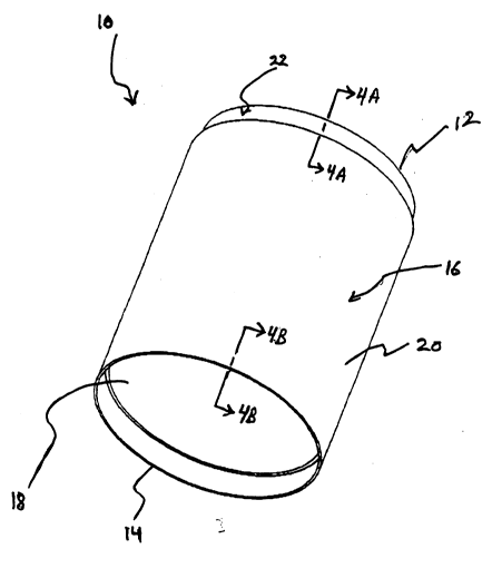
limit same, Fig. l shows a pipe, or conduit, section 10
preferably formed of extruded PVC or polyethylene, although other
materials may be used. The extrusion process used to form pipe
section 10 is well known by those skilled in the art. Generally
described, the extrusion process begins by introducing plastic
resin into an extruder wherein the material is heated, softened
VOU~l~1~1~1 13
2 1 7~) 1 O J
and forced through a die to form the pipe shape. The extruded
pipe is then partially cooled in a water bath and then passes
through a pulling device that pulls the extruded pipe from the
die and through the water bath.
Normal production speeds for pipe made in pipe-
extrusion operations vary between 300 and 3500 lbs/hr depending
upon the pipe size being manufactured. Preferred nominal pipe
sizes, the term nominal as used herein meaning the target
manufacturing dimension, produced in a stAn~rd manufacturing
process vary between 4" and 36" in outer diameter ("OD") and
between 0.200" and 2.00" in wall thickness, although other pipe
sizes could be used. As will be understood by those skilled in
the art, however, when extruding a cylindrical plastic pipe, the
outer dimension, the inner dimension and the shape, or roundness
of the pipe, vary within a given range known as manufacturing
tolerances. Pipe section 10 has a first end 12 a second end 14,
and an annular wall 16 having an inner surface 18 and an outer
surface 20.
After the pipe is formed, it is cut into individual
sections by a sawing device. Simultaneously, a router attached
to the saw device cuts away some of the material on outer surface
20 of the pipe to form a first joint member, which is described
in more detail below. The router is guided by outer surface 20
of pipe section 10, which enables the tool to form a uniform, or
constant, width profile in wall 16, as will also be described
further below. The sawing device, router and method of guiding
VOU~1~1~1 14
2 1 7 ) I 0 6
by tracking the outer surface of the pipe section are all known
to those skilled in the art.
Referring now to Fig. 2, first end 12 of pipe section
10 is shown. A thickness T of wall 16 is defined between inner
surface 18 and outer surface 20. Fig. 2 intentionally
exaggerates the variation in wall thickness of pipe section 10 so
as to make the problem clear to the reader, the actual tolerances
in wall thickness typically vary from +/- .020" to +/- .060",
depending upon the nominal thickness of annular wall 16. For
example, in a 36" OD pipe having a nominal wall thickness of
greater than 1", the manufacturing tolerance is plus or minus
.060". The manufacturing tolerances are usually smaller for pipe
sections having a smaller OD and a smaller wall thicknesses.
As shown in Fig. 2, the thickness of wall 16 varies
because of the manufacturing tolerances of surfaces 18 and 20.
As it will be appreciated by those skilled in the art, the
roundness of pipe section 10 can vary within the manufacturing
tolerances and the pipe can be somewhat oblong or egg-shaped.
Further, inner surface 18, as shown in Fig. 2, is not perfectly
symmetrical therefore, the wall thickness T varies not only from
pipe section to pipe section, but also across the circumference
of any given cross section, as illustrated in Fig. 2.
Figs. 3, 4A and 4B show a pipe section 10 after being
machined to form joint members at each respective end. End 12
has a first joint member 22. Joint member 22 has a first support
surface 24 formed therein, preferably by cutting with a router as
described above. Surface 24 is preferably annular, extending
VOUOZ~lD~lc16Z195.1 15
21 751 06
about the periphery of wall 16. Support surface 24 is preferably
planar and formed perpendicular to the longitudinal axis A of
pipe section 100, however, surface 24 could also be formed at an
angle and have a surface other than planar. Surface 24 has a
constant, or uniform, width, the width of surface 24 being
measured along a line that is perpendicular to axis A and that
extends through the center C, shown in Fig. 2, of pipe section
10. The term constant, as used herein, means that the width of
surface 24 only varies within the relatively small manufacturing
tolerances of a profile formed by a router or similar tool.
Optionally, surface 24 could be created by heat forming
techniques in which pipe section 10 is heated and formed on a
mold. The relatively small manufacturing tolerances referred to
herein range from zero to plus or minus .020", depending on the
OD and wall thickness of the pipe being formed. In a preferred
embodiment, the tolerance is no greater than plus or minus .015".
In a preferred embodiment in which pipe section 10 has a nominal
diameter of 18" and wall 16 has a nominal thickness of .450",
surface 24 has a constant width of .350".
A sealing leg 26 is formed adjacent inner surface 18,
preferably by the same router cut that forms first support
surface 24. Leg 26 extends outwardly from surface 24 and
preferably is annular, extending about the periphery of inner
surface 18. A sealing surface 28 is formed on leg 26 opposite
inner surface 18. Leg 26 has a variable width which depends upon
the thickness of wall 16. As shown in Fig. 4A, the width of leg
26, which is measured between sealing surface 28 and inner
VOU~l~1~1~1 16
2 1 75 1 "6
surface 18, is equal to the difference between the variable
thickness T of wall 16 and the constant thickness of surface 24.
In a preferred embodiment, the nominal thickness of leg 26 is
.100". Leg 26 is shorter than the longitudinal side, or sealing
wall, of the recess formed in the second joint member, which will
be described in greater detail below. In a preferred embodiment,
leg 26 has a nominal length of 1.750". An end 30 is formed in
leg 26, end 30 being cut at an angle.
Turning now to Fig. 4B, a second joint member 32 is
shown. Joint member 32 is preferably formed at a separate
station in the manufacturing process after joint member 22 has
been formed. This station includes a trough that includes an
upper set of wheels and a lower set of wheels, that restrain pipe
section 10 while still allowing it to move in the axial
direction. The upper wheels are idler wheels, meAning that they
are not driven, that hold pipe section 10 in position on the
trough against the bottom wheels. The bottom wheels are driven
and can turn pipe section 10 at various speeds. Both the upper
and lower wheels are angled so that they convey pipe section 10
forward when the drive wheels are operating.
This station also includes a cutting apparatus, which
consists of two major components: a) a plurality of spaced-apart
rollers encircling pipe section 10 and being positioned against
outer surface 20 so as to retain pipe section 10, and b) a fixed
router positioned a fixed distance from the rollers. As the
driven wheels turn and convey pipe section 10 forward, the
plurality of rollers contain outer surface 20 as pipe section 10
VOU~l~1~1~1 17
21 751 C6
-
rotates. End 14 of pipe section 10 is pressed against the fixed
router, which begins to cut away a portion of inner surface 18.
Pipe section 10 continues to be conveyed forward in an axial
direction against the router and the router cuts away more of
inner surface 18. Once the desired axial depth of cut is
achieved end 14 of pipe section 10 will have moved forward far
enough to activate a trip switch, stopping the router.
This operation leaves a second joint member 32 having a
second support surface 34 formed adjacent to outer surface 20.
Support surface 34 is preferably planar and formed.perpendicular
to the longitudinal axis A of pipe section 10, although other
surface configurations could be used. A sealing surface 36 is
formed opposite outer surface 20. Support surface 34 has a
constant width, or thickness, as measured between outer surface
20 and sealing surface 36; the term constant being used in the
same context as for previously described first support surface
24.
A recess wall 38 is formed adjacent inner surface 18
and is preferably perpendicular to inner surface 18 and sealing
surface 36. A recess 40 is defined between sealing surface 36
and recess wall 38. Wall 38 and recess 40 have a variable width,
or thickness, equal to the difference between the variable
thickness of outer wall 16 and the constant width of support
surface 34. In a preferred embodiment, the nominal width of wall
38 and recess 40 are .250". Recess 40 is formed to have a
nominal longitudinal length, which is measured along sealing wall
38, of 2.000". Therefore, the longitudinal length of recess 40
VO~l~1~1~.1 18
21 7'~ G
is preferably .250" greater the longitudinal length of sealing
leg 26, which is 1.750".
Fig. 5 shows a preferred sealing member 50 for use in
the invention, although numerous configurations and materials
could be used. Sealing member 50 is preferably formed of
polyisoprene, EPDM rubber, neoprene, PVC or any suitable
material. Sealing member 50 has a generally planar base 52 and
preferably a plurality of sealing ribs 54 opposite base 52. An
upwardly extending bumper 56 is formed at one end of sealing
member 50 and a flap 58 is formed at the opposite end of sealing
member 50. Flap 58 preferably extends downward at an angle as
shown.
Fig. 6 shows a pipe section 10 in accordance with the
present invention aligned prior to being joined with an identical
pipe, or conduit, section 11, having the same structure and
having been formed in the same manner as previously described
pipe section 10. The first end 12 of pipe section 10 is aligned
to join with second end 14 of pipe section 11. As best seen in
Fig. 7, sealing member 50 is mounted on sealing leg 26 of first
joint member 22, preferably by gluing, although other means of
attachment could be used.
Figure 8 shows a first joint member 22 of pipe section
10, including a sealing member 50, joined with a second joint
member 32 of pipe section 11 to form a joint 100. Alternatively,
joint 100 could be formed between two collar sections or sleeves
and then attached or formed to pipe, or conduit, sections 10 and
11 . -
voLA(ea. Doc lQ195.1 19
2 1 7 5 1 u6
First support surface 24 and second support surface 34align and bumper 56 of sealing member 50 is disposed
therebetween. Alternatively, bumper 56 may not be used in which
case the surfaces 24 and 34 may be in contact. In either case,
when aligned as described herein, surfaces 24 and 34 are said to
be in force-transmitting relationship, meaning that axially-
directed compressive forces exerted on the end of one pipe
section are transmitted to the other pipe section through the
interface of surfaces 24 and 34.
Leg 26, with sealing member 50 attached is generally
disposed within recess 40. Preferably neither the flap 58 or, if
flap 58 is not used, end 30, contacts wall 38 of second joint
member 32. The entire axial compressive force transmitted
through joint 100 is born by surfaces 24 and 34 because leg 26 is
narrow and may buckle or deform under the load.
As can be seen in Fig. 8, because surfaces 24 and 34
have a constant width, the outer surfaces 16 join to form a
smooth outer surface across joint 100. The term smooth, as used
herein, meaning that the outer surfaces 16 of two joined pipe
sections align in a generally parallel fashion, meaning that they
align according to the structure and manufacturing tolerances of
the present invention.
Furthermore, because surfaces 24 and 34 have a constant
width and surface 34 is not as wide as surface 24, a constant-
width, or uniform, gap G is formed between surface 28 of leg 26
and sealing surface 36, as best seen in Figs. 4A and 8. The term
constant, when used in this context, has the same meaning as
VOU~l~1~1~1 20
21 751 06
previously described for the widths of surfaces 24 and 34.
Therefore, sealing member 50 will always fit properly in the gap.
As it will be appreciated, if gap G were too large, sealing
member 50 would not adequately seal joint 100. If gap G were too
small, sealing member 50 would not fit and first sealing member
22 and second sealing member 32 could not be joined.
Having thus described preferred embodiments of the
invention, other variations and embodiments that do not depart
from the spirit of the present invention will become readily
apparent to those skilled in the art. The scope of the present
invention is thus not limited to any one particular embodiment
but is instead set forth in the appended claims and the legal
equivalents thereof.
2.,o