Note: Descriptions are shown in the official language in which they were submitted.
~ 2175167 ~
- 1 - CFO 11519 ~YS
LIQUID EJECTING METHOD WITH MOVABLE MEMBER
BACKGROUND OF THE INVENTIQN
Field of the InventiQr~
The present invention reLates to a liquid
e~ecting head for e~ectlng a desired liquid, utilizing
formation of bubble, a head cartridge using the liquid
e~ecting head, a liquid e~ecting apparatus, a liquid
e~ecting method, a recording method, and a head used in
these methods.
More particularly, the present invention
relate6 to a liquid e; ecting method and a recording
method using a liquid e jecting head with a movable
member arranged to be 1; cr~ hl r~ making use of
generation of bubble.
The present invention is applicable to
equipment such as a printer, a copying machine, a
facsimile machine having a, ~n; ~-~tion system, a word
processor having a printer portion or the like, and an
industrial recording device combined with one or more
of various processing devices, with which recording is
effected on a recording medium such as paper, thread,
fiber, textile, leather, metal, plastic material,
glass, wood, ceramic material, and so on.
In this specification, "recording" means not
only forming an image of letter, figure, or the like
having specific meaning, but also forming an image of a
. ~
~ 2175167
pattern having no specific meaning.
Related B~-~k- round Art
A conventionally known ink j et recording method
5 is the one in which a state of ink is changed to cause
an instantaneous volume change (generatlon of bubble),
so as to e~ ect the ink through an ej ection outlet by
acting force resulted from the state change, whereby
the ink i8 deposited on the recording medium to form an
10 image thereon. As disclosed, for example, in United
States Patent No . 4, 723 ,129, a recording device uslng
this recording method usually compriæes an e; ection
outlet for e~ecting the ink, an ink flow path in fluid
communication with the e~ection outlet, and an
15 electrothermal tr~n~ pr aæ an energy generating
means, disposed in the ink flow path, for e~ecting the
ink .
By this recording method a high quality image
can be recorded at high speed and with low noise and
20 such e~ection outlets for ejecting the ink may be
arranged in high density in a head for performing this
recording method. Therefore, the recording method has
a lot of excellent points; for example, the device
compact in size can obtain an image recorded in high
25 resolution and can also read; 1 y obtain a color image.
Because of it, the ink jet recording method is now
widely used in printers, copying r~-hin~q, facæimile
. -. 2~75167
-- 3 --
h~n.oc, or other office equipment, and even in
industrial systems such as a textile printing device or
the like.
With spread of use of the ink j et technology in
products in wide fields, a variety of demands described
below are increasing these years.
For example, an example of investigation to
meet the demand to improve the energy use ~f f i ri ~nry is
optimization of the heat generating element such as
ad justment of the thl rl~nP~ of a protection film. This
technique is effective to an i, uv~ t in transfer
.ffirionry of heat generated into the liquid.
In order to provide high-quality images,
proposed were driving conditions for rl~l i 7; n~ the
liquid e~ection method or the like capable of
performing good ink ejection based on high-speed
ejection of ink and stable generation of bubble. From
the standpoint of high-speed recording, proposed was an
impL.,~, ~ in a configuration of flow passage in order
to obtain a liquid ejecting head with high filling
(rl~fillinr) speed of the liquid ejected, into the
liquid flow path.
Among this configuration of liquid passage, the
publication of Japanese Laid-open Patent Application
No. 63-199972 or the like describes the flow passage
structure as shown in Figs. lA and lB. The flo~
passage structure and the head producing method
2175167
-- 4 --
described in this publication concern the invention
accomplished noting the back wave occurring with
generation of bubble ( i . e., the pressure directed in
the opposite direction to the direction toward the
5 e~ection outlet, which is the pressure directed to a
li(luid chamber 12 ) . This back wave is known as loss
energy, because it is not energy directed in the
e~ection direction.
The invention shown in Figs. lA and lB
0 rl i Cl~ 'lR~'R a valve lO located apart from a bubble
generation region ormed by a heat generating element 2
and on the opposite side to the ejection outlet ll with
respect to the heat generating element 2.
In Fig. lB, this valve 10 is illustrated as
15 being produced by the producing method making use of a
plate material or the like, having an initial position
where it is stuck to the ceiling of the f low path 3,
and dropping into the flow path 3 with generation of
bubble. This invention is disclosed as the one for
20 suppressing the energy losses by controlling a part of
the back wave by the valve lO.
However, as apparent f rom investigation on the
case where a bubble is generated inside the 10w path 3
as retaining the liquid to be e ~ ected in this
25 structure, to regulate a part of the back wave by the
valve lO is not practical for eJection of liquid.
The back wave itsel ~lr~ln:~l ly has no direct
_ 5 _ 2 ~ 75 1 6 7
relation with e jection, as discussed previously. At
the point when the back wave appears ln the flow path
3, as shown in Fig. lB, the pressure directly related
to ejectlon out of the bubble is already ready to eject
5 the liquid from the flow path 3. It ls thus clear that
to regulate the back wave, more accurately, to regulate
a part thereof, cannot give a great ef f ect on ej ection .
In the bubble ~et recording method utilizing
the bubble generated by the heat generating element, on
10 the other hand, heating is repeated while the heat
generating element is in contact with the ink, which
forms a deposit due to scorch of ink on the surface of
the heat generating element. A large amount of the
deposit could be formed AF~ nrll ng upon the type of ink,
15 which could result in unstable generation of bubble and
which could make it dif f icult to ej ect the ink in good
order. It has been desired to achieve a method for
well ejecting the liquid without rhAn~n~ the ~ y
of the liquid to be e~ected even if the liquid to be
20 eJ ected is the one easily deteriorated by heat or even
if the liquid is the one not easy to achieve ade~auate
generation of bubble.
From this viewpoint, another proposal was made
to provide a method to employ different types of
25 liquids, a liquid (bubble generation liquid) for
generating a bubble by heat and a liquid (e~ection
liquid) to be e~ected, arranged to transmit the
. l
- 6 - 2 1 75 1 6 7
pressure upon generation of bubble to the e~ection
liquid and to e~ect the e~ection liquid thereby, for
example as disclosed in Japanese Laid-open Patent
Applications No. 61-69467 and No. 55-81172, United
States Patent No. 4,480,259, and so on. In these
publications, the ink as the e~ection liquid is
perfectly 2~Gyc~ Gd from the bubble generation liquid
by a fl~X~hl~ film such as s~ n~ rubber so as to
keep the e~ection liquid from directly contacting the
heat generating element, and the ylGS~UlG upon
generation of bubble in the bubble generation liquid is
transferred to the e~ection liquid through deformation
of the flexible film. By this structure, the method
achieved prevention of the deposit on the surface of
the heat generating element, an ~, U~jG 1 in freedom
of selection of the ejection liquid, and so on.
SUMMARY OF THE INVENTIQN =
The present invention provides a novel ejecting
method capable of achieving basic e~ecting properties
which have never been achieved by the flln~l ~c.lly
conventional methods arranged to eJect the liquid as
forming a bubble (especially, a bubble caused by film
boiling) in a liquid flow path.
The present invention provldes a liquid
ejecting condition that is effectiva to adequately
respond to a dispersion factor in an ejection outlet
2175167
7 --
portion, which has been unsolved by the conventional
liquid ejecting prlnciple, and that can achieve an
excellent ejection efficiency. Particularly, the
present invention provides a liquid e~ ecting method
5 effective to the dispersion factor in producing a
plurality of such ejection outlet portions.
Further, the present invention also provides a
liquid ejecting head that can realize more certain and
more reliable effects of the e~ecting method according
10 to the present invention.
This head according to the present invention is
the one obtained by t~r.hn1 r.~l 1 y developing the
knowledge gained in a prlor application, based on a new
standpoint. The summary of this prior application is
15 given in the following.
As disclosed in the prior application, a
movable member is provided in a flow path, and the
fulcrum and free end of the movable member are arranged
in such a positional relation that the f ree end is
20 located on the e~ection outlet side, that is, on the
downstream side. Further, the movable member is
arranged to f ace a heat generating element or a bubble
generation region. This est~hl i ~hr~1 the utterly novel
technology that the bubble is positively controlled by
25 this arrangement.
Next, it was f ound that, considering the energy
given to e jection by the bubble itself, a maximum
- 8 - 2 1 75 1 6 7
factor to l-fmc~ rably improve the ejection properties
was to take account o a downstream growing component
of the bubble. Namely, it was also clarified that the
ejection efficiency and e~ection rate were improved by
5 effectively nl ~gn1n~ the direction of the downstream
growing component of the bubble with the e; ection
direction. This led some of the present inventors to
an ~s L ~ 1 y high technical level, as compared with the
conventional technical level, that the downstream
10 growlng ~ u~ lL of the bubble is positively moved to
the free end side of the movable member.
Further, it was found that it was also
preferred to take account of structural elements such
as the movable member, the liquid flow path, and so on
15 related to growth of bubble on the downstream side in
the heating region for forming the bubble, for example,
on the downstream side from the center line passing the
center of the area of the electrothermal transducer in
the direction of f low of liquid or on the downstream
20 side from the center of the area of a surface
contributing to bubble generation.
It was further found that the r~f;llin~ rate
was able to be ~reatly improved taking account of the
location of the movable member and the structure of the
25 liquid supply passage.
In particular, the present invention was
accomplished noting that variations in an e~ection
9 2175t67
state occurred because of a dispersion faetor in
manufacturing the eonfiguration of e~ection outlet.
Then the illv~ k~ls iinally derived the epoch-making
technology to stabilize the ejection state as further
5 improving the ejection ~ff;r~1~n~-y of liquid by taking
account of a relat~r~nchll? between a ~1~r~ 1, angle
of the movable member and an angle of a line connecting
a fulcrum portion of the movable member with an
intersecting point of a center axis of an eJection
10 outlet with a surfaee (eonnection surfaee) of an
ej eetion outlet portion eonneeted to a liquid f low path
and as also utilizing the epoeh-making liquid e~eetion
method and prineiple in the prior applieation.
Main ob~ eets of the present invention are as
15 follows.
A f irst ob; eet of the present invention is to
provide a liquid e~ecting method, a liquid ejecting
head, and so on that can aehieve a more stz~hi 1 i 7~.1
eJection state by maintaining in a predetermined range,
20 with respect to the reference at a position of a
reference surf ace of the movable member, the
relationship between the angle of the axis connecting
the fulcrum portion of the movable member with the
intersecting point of the eenter axis of the ej ection
25 outlet with the surface of the e~ection outlet portion
connected to the liquid flow path and the displacement
angle upon maximum displacement of the movable member
2175167
-- 10 --
provided with the free end for controlling a bubble
generated (the angle of maximum ~1;CP1RI t).
A second object of the present invention is to
provide a liquid ejecting method, a liquid ejecting
head, and so on that can largely decrease ~r(~llmil1; tion
of heat in the liquid above the heat generating element
as improving the e~ection efficiency and e~ection force
in addition to the first ob~ect and that can perform
good liquid ejection by decreasing residual bubbles
above the heat generating element.
A third object of the present invention is to
provide a liquid e~ ecting head etc . f~nh~nl-~d in
r~f1 l l 1ng frequency and improved in print speed or the
like by suppressing the action of inertial force in the
opposite direction to the li~auid supply direction due
to the back wave and (l~r.r~c:i ng a meniscus back amount
by a valve function of the movable member.
Additionally, a fourth object of the present
invention is to provide a li~uid ejecting method, a
liquid ejectlng head, and so on that reduces a deposit
on the heat generating element, that can broaden the
application range of the eJection lisEuid, and that can
demonstrate m~n5i~rably high eJection efficiency and
e; ection force .
A fifth object of the present invention is to
provide a liquid ejecting metilod, a liquid ejecting
head, and so on having increased degrees o~ freedom of
1~ - 11 2 1 7 5 1 67
selection of the liquid to be e~ ected.
Typical features of the present invention for
achieving the above ob~ects are as follows.
According to an aspect of the present
5 invention, there is provided a liguid ejecting method
for eJecting a liquid, comprising:
using a liquid eJ ecting head having an eJ ection
outlet portion having an eJection outlet for eJecting
the liquid, a liquid flow path in fluid communication
10 with the eJection outlet portion, a bubble generation
region for generating a bubble in the liquid, and a
movable member disposed to face the bubble generation
region and provided with a free end closer to the
e~ection outlet portion than a fulcrum portion thereof,
15 and ~ rl ;~--; n~ the movable member by a pressure based
on generation of the bubble from a position of a
reference surface to a position of a maximum
displ ~ ~, thereby eJecting the liquid,
wherein a relation of 2e~ - 5 5 e~l 5 2eE + 5
20 is satisfied where, with a reference of the reference
surface, e,~ is an angle of the movable member at the
maximum displacement thereof about the fulcrum portion
and el is an angle of an axis connecting the fulcrum
portion with an intersecting point of a center axis of
25 the eJection outlet with a connecting surface of the
eJection outlet portion to the liquid flow path, and
wherein e,~ is an acute angle.
-12- 21751~i7
According to another aspect of the present
invention, there is provided a liquid e jecting method
comprising:
using a li~uid e~ecting head having an e~ection
5 outlet portion having an e~ection outlet for e~ecting a
liquid, a first liquid flow path in fluid, ~ tion
with the e~ection outlet portion, a second liquid flow
path having a bubble generation region, and a movable
member disposed to f ace the bubble generation region
10 and provided with a free end closer to the e~ection
outlet portion than a fulcrum portion thereof,
generating a bubble in the bubble generation region,
and displacing the movable member by a pressure based
on generation of the bubble from a position of a
15 reference surface to a position of a maximum
displacement, thereby e~ecting the li~uid,
wherein a relation of 23E ~ 5 ~ ~n S 2~ + 5
is satisfied where, with a reference of the reference
surface, ~3M iS an angle of the movable member at the
20 maximum displacement thereof about the fulcrum portion
and ~,5 is an angle of an axis connecting the fulcrum
portion with an intersecting point of a center axis of
the e~ection outlet with a connecting surface of the
e~ection outlet portion to the liquid flow path, and
25 wherein ~3M is an acute angle.
According to another aspect of the present
invention, there is provided a liquid e~ecting method
~ - 13 _ 2 1 75 1 67
for ejecting a liquid, comprising:
using a liquid e~ecting head having an e~ection
outlet portion having an eJection outlet for e;~ecting
the liquid, a liquid flow path in fluid communication
5 with the e~ection outlet portion, a bubble generation
region for generating a bubble in the liquid, and a
movable member disposed to f ace the bubble generation
region and provided with a free end closer to the
ejection outlet portion than a fulcrum portion thereof,
10 and ~ rl A~ n~ the movable member by a pressure based
on generation of the bubble from a position of a
reference surface to a position of a maximum
displ A~ 1,, thereby e~ecting the liquid,
wherein a.relation of 2~L - 7 ~ 0,~ 5 2~ + 7
15 is satisfied where, with a reference of the reference
surface, ~,, is an angle of the movable member at the
maximum displacement thereof about the fulcrum portion
and OE is an angle of an axis connecting the fulcrum
portion with an intersecting point of a center axis of
20 the e~ ection outlet with a connecting surf ace of the
e~ection outlet portion to the liquid flow path, and
wherein ~3M iS an acute angle.
According to another aspect of the present
invention, there is provided a liquid ejecting method
25 comprlslng:
using a liquid ejecting head having an ejection
outlet portion having an ejection outlet for e;lecting a
2~75167
14
liquid, a first liquid flow path in fluid communication
with the efection outlet portion, a second liquid flow
path having a bubble generation region, and a movable
member disposed to face the bubble generation region
5 and provided with a free end closer to the e~ection
outlet portion than a fulcrum portion thereof,
generating a bubble in the bubble generation region,
and fl~cpli~ n~ the movable member by a pressure based
on generation of the bubble from a position of a
lO reference surface to a position of a maximum
displ ~1 ~, thereby e~ecting the li~auid,
wherein a relation of 2eE - 7 s ~r~ s 2OE + 7
is satisfied where, with a reference of the reference
surface, ~3n is an angle of the movable member at the
15 maximum displ~ t thereof about the fulcrum portion
and ~3E is an angle of an axis connecting the fulcrum
portion with an intersecting point of a center axis of
the e~ection outlet with a connecting surface of the
e~ection outlet portion to the li~uid flow path, and
20 wherein ~3n is an acute angle.
According to another aspect of the present
invention, there is provided a liquid e~ecting method
for e~ecting a liquid, comprising:
using a liquid e~jecting head having an e~ection
25 outlet portion having an e~ection outlet for e jecting
the liquid, a liquid flow path in fluid, ~ tion
with the e~ ection outlet portion, a bubble generation
` ~ 2 1 75 1 67
-- 15 --
region for generating a bubble in the liquid, and a
movable member disposed to face the bubble generation
region and provided with a free end closer to the
eJ ection outlet portion than a fulcrum portion thereof,
and fli crl Rr1 n~ the movable member by a pressure based
on generation of the bubble from a position of a
reference surface to a position of a maximum
.11 ~rl Rl ~ 1_, thereby e~ecting the liquid,
wherein a relation Of ~M S 2~B + 5 is satisfied
where, with a reference of the reference surface, eM is
an angle of the movable member at the maximum
displacement thereof about the fulcrum portion and ~B is
an angle of an axis connecting the fulcrum portion with
an intersecting point of a center axis of the e~ ection
outlet with a connecting surface of the ejection outlet
portion to the liquid flow path, and wherein OM is an
acute angle and is not less than an angle of an axis
connecting the fulcrum portion with an uppermost end of
the ejection outlet portion of the connecting surface.
According to another aspect of the present
invention, there is provided a liquid ejecting method
for ejecting a liquid, comprising:
using a liquid e jecting head having an eJection
outlet portion having an ejection outlet for ejecting
the liquid, a liquid flow path in fluid, Ini(-Rtion
with the eJection outlet portion, a bubble generation
region for generating a bubble in the liquid, and a
- 16 _ 2 f 75 1 67
movable member disposed to face the bubble generation
region and provided with a free end closer to the
ejection outlet portion than a fulcrum porticn thereof,
and fl~.~plul~.ln~ the movable member by a ~ `UL~ based
5 on generation of the bubble from a posltion of a
reference surface to a position of a maximum
11~ crl A~- t, thereby eJecting the liquid,
wherein a relation of 2~E - 5 eM ~ 2~ is
satisfied where, with a reference of the reference
surface, eM is an angle of the movable member at the
maximum disrl ~- L thereoL about the fulcrum portion
and e, is an angle of an axis connecting the fulcrum
portion with an intersecting point of a center axis of
the e~ection outlet with a connecting surface of the
e~ection outlet portion to the liquid flow path, and
wherein eM is an acute angle and is not less than an
angle of an axis connecting the fulcrum portion with an
uppermost end of the ejectLon outlet portion of the
connecting surf ace .
According to another aspect of the present
invention, there is provided a liquid e~ecting head for
e~ecting a liquid, comprising:
an ejection outlet portion having an ef ection
outlet for e~ecting the liquid, a liquid flow path in
fluid ~ tion with the e~ection outlet portion, a
bubble generation region for generating a bubble in the
liquid, and a movable member disposed to face the
- 17 _ 2 1 7 5 1 6 7
bubble generation region and provided with a free end
closer to the e; ection outlet portion than a f ulcrum
portion thereof, wherein, upon displacing the movable
member by a pressure based on generation of the bubble
5 from a position of a reference surface to a position of
a maxlmum displacement to eject the liquid,
a relation of 2el - 5 < eM < 2e~ + 5 is
. satisfied where, with a reference of the reference
surface, e~, is an angle of the mova~le member at the
10 maximum ~11 cpl ~, ~t thereof about the fulcrum portion
and e,~ is an angle of an axis connecting the fulcrum
portion witn an intersecting point of a center axis of
the ejection outlet with a connecting surface of the
e~ection outlet portion to the liquid flow path, and
15 wherein e~, is an acute angle.
According to another aspect of the present
invention, there is provided a liquid e~ecting head
comprising:
an e~ection outlet portion having an e~ection
20 outlet for e~ecting a liquid, a first liquid flow path
in fluid communication with the e~ection outlet
portion, a second liquid flow path having a bubble
generation region, and a movable member disposed to
face the bubble generation region and provided with a
25 free end closer to the e~ection outlet portion than a
fulcrum portion thereof, wherein, upon generating a
bubble in the bubble generation region and displacing
~ - 18 - 2 1 7 5 1 6 7
the movable member by a pressure based on the
generation of the bubble from a position of a reference
surface to a position of a maximum displacement to
eject the liguid, a relation of 2~E ~ 5 5 ~3M 5 2~3E + 5
5 is satisfied where, with a reference of the reference
surface, eM is an angle of the movable member at the
maximum rlierl~l 1 thereof about the fulcrum portion
and ~3E is an angle of an axis connecting the f ulcrum
portion with an intersectin~ point of a center axis of
10 the e ~ection outlet with a connecting surface of the
e~ection outlet portion to the liquid flow path, and
wherein ~M i8 an acute angle.
According to another aspect of the present
invention, there is provided a liguid e~ecting head for
15 ejecting a liquid, comprising:
an e~ection outlet portion having an e~ection
outlet for e~ecting the liquid, a liguid flow path in
f luid communication with the e~ ection outlet portion, a
bubble generation region for generating a bubble in the
20 liquid, and a movable member disposed to face the
bubble generation region and provided with a free end
closer to the e~ection outlet portion than a fulcrum
portion thereof, wherein, upon displacing the movable
member by a pressure based on generation of the bubble
25 from a position of a reference surface to a position of
a maximum disrl ~r.~- t to eJeCt the li~uid,
a relation of 2~E ~ 7 S ~M 5 2~E + 7 is
-19- 2175167
satisfied where, with a reference of the reference
surface, e" i8 an angle of the movable member at the
maximum .1~ , t thereof about the fulcrum portion
and eE is an angle of an axis connecting the fulcrum
5 portion with an intersectin~ point of a center axis of
the efection outlet with a connecting surface of the
e~ectlon outlet portlon to the liquid flow path, and
wherein e" i8 an acute angle.
According to another aspect of the present
lO invention, there ls provided a liquid ejecting head
comprising:
- an eJ ection outlet portion having an e~ ection
outlet for e~ecting a liquid, a first liquid flow path
in fluid communication with the ejection outlet
15 portion, a second liquid flow path having a bubble
generation region, and a movable member disposed to
f ace the bubble generation region and provided with a
f ree end closer to the ej ection outlet portion than a
fulcrum portion thereof, wherein, upon generating a
20 bubble in the bubble ç~eneration region and displacing
the movable member by a pressure based on the
generation of the bubble from a position of a reference
surface to a position of a maximum disrl ~r -nt to
e~ ect the liquid, a relation of 2eE - 7 5 ~ ~ 2aE ~ 7 '
25 is satisfied where, with a reference of the reference
surface, ~,~ is an angle of the movable member at the
maximum displacement thereof about the fulcrum portion
2~75~67
-- 20 --
and ~,s is an angle of an axis connecting the fulcrum
portion with an lntersecting point of a center axis of
the e ~ection outlet with a connecting surface of the
e~ection outlet portion to the liquid flow path, and
wherein ~n is an acute angle.
According to another aspect of the present
invention, there is provided a liquid e~ecting head for
e~ecting a liquid, comprising:
an e~ ection outlet portion having an e~ ection
outlet for e~ecting the liquid, a liquid flow path in
fluid communication with the e~ection outlet portion, a
bubble generation reglon for generating a bubble in the
liquid, and a movable member disposed to face the
bubble generation region and provided with a free end
closer to the e lection outlet portion than a fulcrum
portion thereof, in which the movable member is
fliqp~ by a pressure based on generation of a bubble
from a position of a reference surface to a position of
a maximum displacement to e~ect the liquid,
wherein a relation of ~n 5 2~3, + 5 is satisf ied
where, with a reference of the reference surface, ~3n is
an angle of the movable member at the maximum
displacement thereof about the fulcrum portion and 0~ is
an angle of an axis connecting the fulcrum portion with
an intersecting point of a center axis of the e~ ection
outlet with a connecting surface of the eJection outlet
pcrtion tc the liquid flow path, and wherein ~3n is an
2175167
-- 21 --
acute angle and is not less than an angle of an axis
connecting the f ulcrum portion with an uppermost end of
the ejection outlet portion of the connecting surface.
According to another aspect of the present
invention, there is provided a liquid e~ecting head for
e~ ecting a liquid, comprising:
an e~ection outlet portion having an e~ection
outlet for e~ecting the liquid, a liquid flow path in
fluid communlcation with the ejection outlet portion, a
bubble generation region for generating a bubble in the
liquid, and a movable member disposed to face the
bubble generation region and provided with a free end
closer to the ej ection outlet portion than a f ulcrum
portion thereof, in which the movable member is
displaced by a pressure based on generation of a bubble
from a position of a reference surface to a position of
a maximum displacement to eject the liquid,
wherein a relation of 2CE ~ 5 S ~3M S 2OE is
satisfied where, with a reerence of the reference
surface, ~3" is an angle of the movable member at the
maximum ~; crl ~( t thereof about the fulcrum portion
and ~3E is an angle of an-axis connecting the fulcrum
portion with an intersecting point of a center axis of
the ejection outlet with a connecting surface of the
ejection outlet portion to the liquid flow path, and
wherein ~, is an acute angle and is not less than an
angle of an axis connecting the fulcrum portion with an
` 5 ~ 2~75~67
-- 22 --
uppermost end of the e~ectlon outlet portion of the
connecting surface.
According to another aspect of the present
invention, there is provided a liquid ejecting
5 apparatus having the liquid e; ecting head as descrlbed
in either one of the above aspects, and driving signal
supply means for supplying a driving signal for
e~ecting the liquid from the liquid e~ecting head.
According to another aspect of the present
10 invention, there is provided a liquid eJ ecting
apparatus having the liquid eJecting head as described
in either one of the above aspects, and recording
medium conveying means f or conveying a recording medium
for receiving the liquid e~ected from the liquid
15 ejecting head.
According to the present invention, the
eJection state of the liquid was able to be stabilized
by properly ~lPfin~n~ the maximum displacement angle at
the time when the movable member for controlling the
20 bubble generated is displaced at maximum by generation
of bubble, with respect to the angle of the line
connecting the fulcrum portion of the movable member
with the intersecting point of the center axis of
ejection port or the area center a~is with the surface
25 of the e~ection outlet portion connected to the liquid
f low path .
In addition, the liquid ejecting method, head,
2175~67
-- 23 --
and so on according to the present invention, based on
the very novel eJection principle, can attain the
synergistic effect of the bubble generated and the
movable member displaced thereby, so that the liquid
5 near the ejection outlet can be ~ff1~1Pntly e~ected,
thereby improving the ejection Pff;m;~n~y as ~ , ~d
with the conventional ejection methods, heads, and so
on of the lnk jet method. For example, the most
preferable form of the present invention achieved a
10 quantum leap of e~ection efficiency two or more times
improved .
With the characteristic structures of the
present invention, e jection failure can be yl~v~ ted
even after long-term storage at low temperature or at
15 low moisture, or, even if e jection failure occurs, the
head can be advantageously returned instantaneously
into a normal condition only with a recovery process
such as pr~l imini~ry e~ection or suction recovery.
Specifically, under the long-term storage
20 condition to cause eJection failure of almost all of
ef ection outlets in the head of the conventional ink
jet method having sixty four ejection outlets, the head
of the present invention showed ejection failure only
in approximately half or less of the ejection outlets.
25 For recovering these heads by prel im;n:~rily e;~ection,
several thousand prPl im~n::~ry e~ections were required
for each ejection outlet in the conventional head,
2~75~67
- 24 --
whereas a hundred or so prl~l ;minArily ejections were
sufficient to recover the head of the present
invention. This means that the present invention can
shorten the recovery period, can decrease losses of the
5 liquid due to recovery, and can greatly lower the
running cost.
Particularly, the structures for improving the
ref illing characteristics of the present invention
achieved high responsivity upon continuous e~ection,
stable growth of bubble, and 5ti 1h~ 11 7ation of liquid
droplet and realized high-speed recording or high-
quality recording based on the high-speed liquid
e~ ection .
The other effects of the present invention will
15 be understood from the description of the embodiments.
In the specification, the terms "upstream" and
"downstream" are defined with respect to a general
liquid flow from a liquid supply source through the
bubble generation region ( or the movable member ) to the
20 ejection outlet or are expressed as expressions as to
the direction in this structure.
Further, a "downstream side" portion of the
bubble itself represents an eJection-outlet-side
portion of the bubble which directly functions mainly
25 to e~ect a liquid droplet. More particularly, it means
a downstream portion of the bubble in the above flow
direction or in the direction of the above structure
2~75167
.
-- 25 -
with respect to the center of the bubble, or a bubble
appearing in the downstream region from the center of
the area of the heat generating element.
In this specification, a "substantially sealed"
state generally means a sealed state in such a degree
that, when a bubble grows, the bubble does not escape
through a gap (slit) around the movable member before
motion of the movable member.
In this specification, a "partition wall" may
mean a wall (which may include the movable member)
interposed to separate the region in direct fluid
communication with the e~ection outlet from the bubble
generation region in a wide sense, and more
specifically means a wall separating the liquid flow
path including the bubble generation region from the
liquid flow path in direct fluid, Inl~tion with the
e~jection outlet, thereby preventing mixture of the
liquids in the respective liquid flow paths in a narrow
sense .
In the specification, a "free end portion" of
the movable member means a portion including the free
end, which is a downstream-side end of the movable
member, and neighboring regions, and also ~nrlll~in~ a
portion near the downstream corners of the movable
member.
Further, a "free end region" of the movable
member means the free end itself at the downstream-side
2175167
- 26 -
end of the movable member, a region including the slde
ends of the free end, or a region including both the
f ree end and ~he slde ends .
Further, the "fulcrum portion" of the movable
5 member stated herein means a border portion between a
displacing portion of the movable member and a portlon
substantially not displaced, for example, in the case
of the movable member being formed by a slit in the
partition wall, it corresponds to the end of the cut of
10 sllt, which i5 the position of the root of the movable
member .
Further, the "reference surface" stated herein
means a surlEace including the movable member 31 kept in
a natural state wlthout being displaced as being free
from the external force. ThLs is substantially
equivalent to defining the reference surface as a plane
including the fulcrum o~ the movable member and
connecting the partition wall extending on the
downstream side from the fulcrum to the e;lection outlet
with the partition wall extending on the upstream side
opposlte thereto. If the movable member ls deformed,
the latter can be used as the reference surface.
Further, the "displacement angle" of the
movable member stated herein means an angle around the
center of rotation at the fulcrum portion, of the
stralght line connecting the above-mentloned fulcrum
portion with the free end upon disr~ t of the
2175167
-- 27 --
movable member, with respect to the reference of the
aforementioned reference surface. EspecialLy, the
maximum of this displacement angle is defined as a
maximum diSrl Al: -lt angle ~3M'
Further, the "center axis of e~ection outlet"
means a rotational axis of cylinder in the case of a
cylindrical ejection outlet portion or a straight line
connecting the center of circle of the aperture of the
election outlet portion on the liquid flow path side
(e~ection outlet 18) ~ith the center of circle of the
e~ection outlet portion on the outer surface ( face
surface) side.
If the e~ection outlet portion is not circular,
the "center axis of e~ection outlet" or the "center
axis of the area of e~ection outlet" is defined as a
straight line connecting the center of the area on the
liquid flow path side with the center of the area on
the face surface side.
BRIEF DESC~IPTION OF THE DRA~INGS
Figs. lA and lB are a perspective view of a
conventional liquid e~ ecting head and a sectional view
of a liquid flow path of the conventional liquid
e~ ecting head;
Figs 2A, 2~3, 2C, and 2D are schematic
sectional views of an example of a liquid e~ecting head
applied to the present invention;
2~75~67
- 28 --
Fig. 3 is a partly broken perspective view of a
li~[uid ejecting head applied to the present invention;
Fig. 4 is a schematic view of pressure
propagation f rom a bubble in a conventional head;
Fig. 5 is a schematic view of pressure
propagation from a bubble in a head applied to the
present invention;
Fig. 6 is a schematic view of a liquid flow in
the ejection principle applied to the present
invention;
Fig. 7 is a partly broken sectional view of a
liquid e~ ecting head according to an embodiment of the
present invention;
Fig. 8 is a partly broken perspective view of a
li~uid ejecting head applied to the present invention;
Figs. 9}~, 9B, and 9C show a positional relation
between the heat generating element and the movable
member;
Fig. lO is a schematic drawing to show a first
example of the relation between ~M and ~3E;
Fig. ll is a schematic drawing to show a second
example of the relation between OM and ~3E;
Fig. I2 is a schematic drawing to show a third
example of the relation between ~3M and ~E;
Fig 13 is a schematic drawing to show a fourth
example of the relation between GM and ~E;
Figs. 14~ and 14B are illustrations of an
. ~
. ~ 2l75l67
-- 29 --
operation of a movable member;
Figs. 15A, 15B, and 15C are lllustrations of
other configurations of the movable member;
Fig. 16 is a schematic drawing to show an
5 example of a ceiling stopper for satisfying the
condition of the angle in the present invention;
Figs. 17A and 17B are longitudinal cross
sections of a liquid e~ecting head according to an
embodiment of the present invention;
Fig. 18 is a schematic view of a configuration
of a driving pulse;
Fig. 19 is a sectional view of a supply passage
of a liguid ejecting head in an embodiment of the
present invention;
Fig. 20 is an exploded perspective view of a
head of an embodiment of the present invention;
Fig. 21 is an exploded perspective view of a
liquid e~ ection head cartridge;
Fig. 22 is a schematic illustration of a liquid
20 ejecting device;
Fig. 23 is a block diagram of an apparatus;
Fig. 24 is a schematic view of a liquid
e; ection recording system; and
Fig. 25 is a schematic view of a head kit.
DESCRIPTION OF THE PREFERRED EMBODIMENTS
( Description of principle )
~ 2175~67
The principle o ejection applicable to the
present invention will be ~l-rl~in~l referring to the
drawings .
Figs. 2A to 2D are schematic sectional views of
a liquid e~ecting head, cut along the direction of the
liquid flow path, and Fig. 3 is a partly broken,
perspective view of the liquid e~ Qcting head .
The liquid ejecting head of Figs. 2A to 2D
comprises an element substrate 1, a heat generating
element 2 ( a heat generating resistor in the
configuration of 40 ,um x 105 ,um in Fig. 3 ) as an
ejection energy generating element for supplying
thermal energy to the liquid to eject the liquid,
mounted on the element substrate 1, and a liquid flow
path 10 formed above the element substrate in
correspondence to the heat generating element 2. The
liquid flow path 10 is in i~luid ~ tion with an
e~ ection outlet 18 and with a common liquid chamber 13
for supplying the liquid to a plurality of such liquid
flow paths 10, so that the liquid flow path 10 receives
the liquid in an amount equivalent to the liquid having
been ejected through the e~ection outlet from the
common liquid chamber 13.
Above the element substrate and in the liquid
flow path 10 a movable member 31 of a plate shape
having a flat portion is formed in a cantilever form
and of a material having elasticity, such as a metal,
~; ~
~ 2~75~67
-- 31 --
so as to face the above-mentioned heat generating
element 2 . One end of the movable member is f ixed to a
foundation (support member) 34 or the like provided by
patterning of a photosensitive resin on the wall of the
5 liquid flow path 10 or on the element substrate. This
structure supports the movable member and constitutes a
fulcrum ( fulcrum portion ) 33 .
This movable member 31 has the fulcrum ( fulcrum
portion: fixed end) 33 on the upstream side of a large
10 flow of the liquid from the common liquid chamber 13
through the movable member 31 toward the e~ection
outlet 18, caused by the e~ection operation of the
liquid, and has a free end (free end portion) 32 on the
downstream side with respect to this fulcrum 33. The
15 movable member 31 is so positioned that lt is opposed
to the heat generating element 2 with a gap of
approximately 15 um therefrom so as to cover the heat
generating element 2. A bubble generation reglon is
defined between the heat generating element and the
20 movable member. The type, configuration, and position
of the heat generating element or the movable member
are not limited to those described above, but may be
arbitrarily changed as long as the conf iguration and
position are suitable for controlling the growth of
25 bubble and propagatlon of pressure as ~iscussed below.
For the convenience' sake of descriptlon of the flow of
the liquid discussed hereinafter, the liquid flow path
- 32 _ 2 1 7 5 ~ 6 7
10 as described is divided by the movable member 31
into two regions, i.e., a first liquid flow path 14 in
direct communication with the e~ectlon outlet 18 and a
second liquid flow path 16 having the bubble generation
5 region 11 and the liquid supply passage 12.
Heating the heat ~enerating element 2, heat is
applied to the liquid in the bubble generation region
11 between the movable member 31 and the heat
generating element 2, whereby a bubble is generated in
10 the liquid by the film boiling rhPn~ ~nnn as fl~ rihefl
in the specification of United States Patent No.
4,723,129. The bubble and the pressure raised by the
generation of bubble mainly act on the movable member,
so that the movable member 31 is displaced to widely
15 open on the ejection outlet side about the fulcrum 33,
as shown in Figs. 2B and 2~ or Fig. 3. The
fli crl ~ t or the fli crl nf l~fl state of the movable
member 31 guides the growth of the bubble itself or the
propagation of the pressure raised with generation of
20 the bubble toward the ej ection outlet .
Here, one of the fundamental ejection
principles applied to the present invention will be
P~rl~n~fl One of the most importance pr1n~rl~ in
the present invention is that with the pressure of the
25 bubble or the bubble itself the movable member disposed
to face the bubble is displaced from a first position
in a stationary state to a second position in a state
2 1 7 5 1 6 7
- 33 --
after displaced and the movable member 31 thus
displaced guides the bubble itself or the pressure
caused by the generation of bubble toward the
downstream side where the ejection outlet 18 is
5 positioned.
This principle will be explained as comparing
Fig. 5 showing the present invention with Fig. 4
schematically showing the conventional liquid f low path
structure using no movable member. Here, VA represents
lO the direction of propagation of the pressure toward the
eJection outlet while VD the direction of propagation of
the pressure toward the upstream.
The conventional head shown in Fig. 4 has no
structure for regulating directions of propagation of
15 the pressure raised by the bubble 40 generated. Thus,
the pressure of the bubble 40 propagates in various
directions normal to the surf ace of the bubble as shown
by Vl-V8. Among these, components having the pressure
propagation directions along the direction VA most
20 effective to the liquid e~ection are those having the
directions of propagation of the pressure in the
portion of the bubble closer to the ejection outlet
than the nearly half point, i.e., V1-V4, which is an
important portion directly contributing to the liquid
25 ejection efficiency, the liquid e~ection force, the
e~ection speed, and so on. Further, V1 effectively
acts because being closest to the eJ ection direction VA~
~ 2175167
-- 34 --
and, contrary thereto, V4 involves a relatively small
nPnt directed in the direction of VA~
In contrast with it, in the case of the present
invention shown in Fig. 5, the movable member 31 works
to guide the pressure propagation directions V1-V4 of
bubble, otherwise directed in the various directions in
the case of Fig. 4, toward the downstream side (the
e~ ection outlet slde ) so as to change them into the
pressure propagation direction of VA~ thereby making the
pressure of bubble 40 contribute directly and
effectively to e~ection.
The growing direction itself of bubble is
guided to the d~ x ~L ~ in the same manner as the
pressure propagation directions Vl-V4 are, so that the
bubble grows more on the downstream side than on the
upstream side. In this manner, the e~ection
pffif-;pn~y, the e~jection force, the e~ection speed, and
so on can be f-ln~ lly improved by controlling the
growing direction itself of bubble by the movable
member and controlling the pressure propagation
directions of bubble.
Now returning to Figs . 2A to 2D, the e~ ection
operation of the liquid e~ecting head stated above will
be described in detail.
Fig. 2A shows a state before the energy such as
electric energy is applied to ~he heat generating
element 2, which is, therefore, a state before the heat
_ 35 _ 2175167
generating element generates the heat. An important
point is that the movable member 31 is positioned
relative to the bubble generated by heat generation of
the heat generating element so as to be opposed to at
5 least the downstream side portion of the bubble.
Namely, in order to let the downstream portion of the
bubble act on the movable member, the liquid flow
passage structure is arranged in such a way that the
movable member 31 extends at least up to a position
10 downstream of the center 3 of the area of the heat
generating element ( or downstream of a line passing
through the center 3 of the area of the heat generatlng
element and being perpendicular to the lengthwise
direction of the flow path).
Fig. 2E~ shows a state in which the electric
energy or the like is applied to the heat generating
element 2 to heat the heat generating element 2 and the
heat thus generated heats a part of the liquid filling
inside of the bubble generation re~ion 11 to generate a
20 bubble in accordance with film boiling.
At this time the movable member 31 is displaced
from the first position to the second position by the
pressure raised by generation of bubble 40~so as to
guide the propagation directions of the pressure of the
25 bubble into the direction toward the e~ection outlet.
An important point here is, as described above, that
the free end 32 of the movable member is located on the
~ 2175167
-- 36 --
downstream side (or on the e~ection outlet side) while
the fulcrum 33 on the upstream side ( or on the common
liquid chamber side ) so that at least a part of the
movable member may be opposed to the downstream portion
5 of the heat generating element, that is, to the
downstream portion of the bubble.
Fig. 2C shows a state in which the bubble 40
has further grown and the movable member 31 is further
displaced according to the pressure raised by
10 generation of bubble 40. The bubble generated grows
more downstream than upstream to expand largely beyond
the first position (the position of the dotted line) of
the movable member.
It is thus understood that a gradual
15 disp1~ of the movable member 31 in response to
the growth of bubble 40 allows the pressure propagation
directions of bubble 40 to be uniformly directed toward
the e~ection outlet and allows the bubble to grow in a
direction in which the volume can be readily changed,
20 i . e., in the direction toward the free end, thereby
also inoreaslng the e~ection efficiency. When the
movable member guides the bubble and the bubble
generation pressure toward the e~ection outlet, it
rarely obstructs the propagation and growth and can
25 efficiently control the propagation directions of the
pressure and the growth direction of the bubble in
accordance with the magnitude of the pressure
~ 2175167
-- 37 --
propagating .
Fig. 2D shows a state in which the bubble 40
contracts and extincts because of a decrease of the
pressure inside the bubble after the film boiling
5 stated previously.
The movable member 31 having been displaced to
the second position returns to the initial position
( the first position) of Fig. 2A by restoring force
resulting from the spring property of the movable
10 member itself and the negative pressure due to the
contraction of the bubble. Upon collapse of the bubble
the liquid flows into the bubble generatlon region 11
in order to ,^~~ te for the volume reduction of the
bubble and in order to compensate for the volume of the
15 liquid ejected, as indicated by the flows VD1~ VD2 from
the upstream side ( B ) or the common liquid chamber side
and by the flow Vc from the election outlet side.
The foregoing explained the operation of the
movable member with generation of the bubble and the
20 ejecting operation of the liquid, and then the
following explains refilling of the liquid in the
liquid e~ecting head, applicable to the present
invention .
After Fig. 2C, the bubble 40 experiences a
25 state of the maximum volume and enters a bubble
collapsing process. In the bubble coll~rc:ing process,
a volume of the liquid enough to compensate for the
2175167
-- 38 --
volume of the bubble havin~ collapsed flows into the
bubble generation region from the e~ection outlet side
of the first liquid flow path 14 and from the side of
the common liquid chamber 13 of the second liquid f low
path 16. In the case of the conventional liquid flow
passage structure having no movable member 31, amounts
of the liquid flowing from the ejection outlet side and
from the common liquid chamber into the bubblQ
collapsing position depend upon magnitudes of flow
resistances in the portions closer to the e~ ection
outlet and to the common liquid ohamber than the bubble
generation region ( which are based on resistances of
flow paths and inertia of the liquid).
If the flow resistance is smaller on the side
near the ejection outlet, the liquid flows more into
the bubble collapsing position from the e~ection outlet
side 80 as to increase an amount of retraction of
meniscus. Particularly, as the flow resistance near
the e~ection outlet is decreased so as to raise the
e~ection efficiency, the retraction of meniscus M
becomes greater upon collapse of bubble and the period
of refilling time becomes longer, thus becoming a
hindrance against high-speed printing.
In contrast with it, because this structure
includes the movable member 31, the retraction of
meniscus stops when the movable member returns to the
initial position upon collapse of bubble and thereafter
~ 2175167
-- 39 -
the supply of the liquid for the L~ ~;n;n~ volume of W2
mainly relies on the liquid su~ply from the flow VDZ
through the second flow path 16, where the volume W of
the bubble is split into the upper volume Wl beyond the
f irst position of the movable member and the lower
volume W2 on the side of the bubble generation region
11. I'he retraction of meniscus appeared in the volume
equivalent to approximately a half of the volume W of
bubble in the conventional structure, whereas the above
10 structure enabled to reduce the retraction of meniscus
to a smaller volume, specifically, to approximately a
half of Wl.
Additionally, the liquid supply for the volume
W2 can be forced, using the pressure upon collapse of
15 bubble, along the surface of the movable member 31 on
the heat generating element side and mainly from the
upstream side (VD2) of the second liquid flow path, thus
r~ inS faster rF~f i l l in~.
A characteristic point here is as follows: if
20 rPf; 1 1; n~ is carried out using the pressure upon
collapse of bubble in the conventional head, vibration
of meniscus is so great as to result in deteriorating
the quality of image; whereas, r~f;ll;n~ this
structure can decrease the vibration of meniscus to an
25 e~tremely low level because the movable member
restricts flow of the liquid in the region of the first
liquid flow path 14 on the e~ection outlet side and in
~ _ 40 _ ~75~67
the region on the ej ection outlet side of the bubble
generation region 11.
The above-mentioned structure applicable to the
present invention achieves forced r.of~llin~ of the
liquid into the bubble generation region through the
liquid supply passage 12 of the second flow path 16 and
suppression of the retractlon and vibration of meniscus
as discussed above, so as to perform high-speed
refilling, whereby it can realize stable ejection and
it can also reali2:e an illlJJlU~ t in quality of image
and high-speed recording when employed in applications
of high-speed and repeated ejections or in the field of
recording .
The above structure applicable to the present
invention is also provided with a further effective
function as follows. It is to suppress propagation of
the pressure raised by generation of bubble to the
upstream side (the back wave). The most of the
pressure of the bubble on the side of the common liquid
chamber 13 (or on the upstream side) among the bubble
generated above the heat generating element 2 was
conventionally the force to push the liquid back to the
upstream side ( which is the back wave ) . This back wave
raised the upstream pressure and a liquid movement
amount and caused inertial force due to movement of the
liquid, which degraded the refilling of the liquid into
the liquid flow path and also hindered high-speed
21751~7
-- 41 --
driving. This structure furt~ler improved r~f;11;n~
performance also by suppressing these actions to the
upstream side by the movable member 31
Next explained are further characterlstic
5 structures and effects.
The second liquid flow path 16 has the liquid
supply passage 12 having an internal wall, which is
substantially ~latly continuous from the heat
generating element 2 (which means that the surface of
10 the heat generating element is not stepped down too
much ), on the u~ . side of the heat generating
element 2. In this case, the liquid is supplied to the
bubble generation region 11 and the surface of the heat
generating element 2 along the surface of the movable
15 member 31 nearer to the bubble generation region 11, as
indicated by VD2. This stops stagnation of the liquid
above the surface of the heat generating element 2 and
easily removes the so-called residual bubbles which are
separated out from the gas dissolved in the liquid or
20 which remain without being collapsed. Further, the
heat is prevented from accumulating in the liquid.
Accordingly, stabler generation of bubble can be
repeated at high speed. Although this structure was
explained with the liquid supply passage 12 having the
25 substantially flat internal wall, without having to be
limited to this, the liquid supply passage may be any
having a gentle internal wall smoothly connected to the
2175167
-- 42 --
surface of the heat ~enerating element as long as it is
shaped so as not to cause stagnation of the liquid
above the heat generating element or great turbulent
f low in the supply of liquid .
There occurs some supply of the liquid into the
bubble generatlng region from VD1 through the side of
the movable member ( through the slit 35 ) . In order to
guide the pressure upon generation of bubble more
effectively to the ejection outlet, such a movable
member as to cover the whole of the bubble generation
region (as to cover the surface of the heat generating
element ), as shown in Figs . 2A to 2D, may be employed.
When the movable member 31 returns to the first
position in that case, the flow resistance of the
liquid is so great in the bubble generation region 11
and in the region near the e~ection outlet of the first
liquid flow path 14. In such cases, the liquid is
restricted from flowing from VD1 as described above
toward the bubble generation region 11. Since the head
structure in this structure has the flow VD2 for
supplying the liquid to the bubble generation region,
it has very high supply performance of the liquid.
Thus, the supply performance of the liquid can be
maintained even in the structure with improved ej ection
f~ffi~i~nl-.y in which the movable member 31 covers the
bubble generation region 11.
Incidentally, the positional relation between
_ 43 _ 2175~67
the free end 32 and the fulcrum of the movable member
31 is def ined in such a manner that the f ree end is
located downstream relative to the fulcrum, for example
as shown in Fig . 6 . This structure can ef f iciently
5 realize the function and effect to guide the pressure
propagation direction and the growing direction of
bubble to the ejection outlet upon generation of
bubble, as fl1c~ cFu~ previously. Further, this
positLonal relation achieves not only the f unction and
10 effect for ejection, but also the effect of high-speed
rf~fillin~ as decreasing the flow resistance against the
li~uid flowing in the liquid flow path lO upon supply
of liguid. This is because, as shown in Fig. 6, the
free end 32 and fulcrum 33 are positioned so as not to
15 resist the ~lows S1, S2, S3 flowing in the liquid flow
path 10 ( including the first lic~uid flow path 14 and
the second liquid flow path 16 ) when the meniscus M at
a retracted position af ter ej ection returns to the
ejection outlet 18 because of the capillary force or
20 when the li~uid is supplied to compensate for the
collapse of bubble
Explaining in further detail, in this structure
( Figs . 2A to 2D ) the movable member 31 extends relative
to the heat generating element 2 so that the free end
25 32 thereof is opposed thereto at a downstream position
with respect to the area center 3 ( the line passing
through the center of the area of the heat generating
~ 2175167
- 44 --
element ( through the central portion ) and being
perpendicular to the lengthwise direction of the liquid
f low path ), separating the heat generatlng element 2
into the upstream region and the downstream region, as
described previously. This arrangement causes the
movable member 31 to receive the pressure or the bubble
occurring downstream of the area center posltion 3 of
the heat generating element and greatly contributing to
the e~ection of liquid and to guide the pressure and
bubble toward the e~ection outlet, thus flln~ lly
improving the e~ection efficiency and the ejection
f orce .
Further, many effects are attained as also
utilizing the upstream portion of the bubble in
addition. It is presumed that effective contribution
to the e~ection of liquid also results from
instantaneous -~hi~n1 r~ 1 displacement of the free end
of the movable member 31 in this structure.
( Embodiment l )
The embodiments of the present invention will
be l~rli~1nf~1 with reference to the accompanying
drawings .
I'he present I ' o~ t also employs the same
main principle of e~ection of liquid as described
above. Each embodiment to follow will be ~r1i~;nr~
using a head ln which the first liquid flow path 14 and
the second liquid flow path 16 are separated by the
_ 45 _ 2 1 75 1 6 7
partition wall 30 as in the following description, but
it is noted that, without having to be limited to this,
the present invention can be similarly applied to the
heads ~ n~ l i ng that in the above description of the
5 principle.
Fig. 7 is a schematic sectional view, taken
along the direction of flow path, of the liquid
e~ ecting head in the present embodiment .
The liquid e~ecting head oi the present
10 invention has an element substrate 1 and a heat
generating element 2, mounted thereon, for supplying
the thermal energy for generating a bubble in the
liquid, and above the element substrate 1 there are
provided a second liquid flow path 16 for bubble
15 generation liquid and a first liquid flow path 14 for
e~ection liquid in direct communication with an
e~ection outlet portion 28 having an ejection outlet,
disposed above the second liquid flow path. A
partition wall 30, made of a material having
20 elasticity, such as a metal, is disposed between the
first liquid flow path 14 and the second liquid flow
path 16 and separates the e~ection liquid inside the
first liquid flow path 14 from the bubble generation
liquid in the second liquid flow path 16. E~ere, a same
25 liquid may be used as the e~ection liquid and as the
bubble generation liquid, similarly as in the
description of principle stated previously. In that
~ 2~75167
-- 46 --
case, a communication portion (not shown) may be formed
in at least a part of the partition wall 30 so that the
liquid may flow between a first common liquid chamber
15 communicating with the first flow path and a second
common liquid chamber 17, ; ~i lting with the second
flow path 16.
The e~ection outlet portion 28 has an opening
portion of a small diameter (e~ection outlet 18)
through which a liquid droplet i8 eJected from the head
and an aperture portion of a large fll~ L as a
connecting portion with the first liquid flow path 14.
The center axis and an extension thereof perpl~nfl;~ r
to the e~ectlon outlet 18 are nearly aligned with the
center axls C along a directlon ln which the liquid
droplet flies after e~ected. Further, S represents an
intersecting point between the above center axis C and
a surf ace corresponding to the connecting portion
between the e~ectlon outlet portion 28 and the first
liquid flow path 14.
Similarly as in the above-descrlption of
principle, a slit aperture portion ( a slit, see Fig.
9A) 35 is formed in the partition wall 30 at a portion
located in a pro~ection space above the surface of heat
generating element (which will be referred to as an
e~ection force generating region, including the region
of A and the bubble generation region of B in Fig . 7 ) .
The movable member 31 is provided as being capable of
~ 21 751 67
-- 47 --
substantially sealing this slit 35. Sp~ l y, the
movable member 31 is a member shaped in a cantilever
form having a free end on the e~ection outlet 18 side
( or on the downstream side of the f low of liquid ) and a
f ixed end on the f irst/second common liquid chamber
(15, 17~ side and being rotatable about a fulcrum
portion 33 of the fixed end. A8 shown in the drawing,
the movable member 31 faces the bubble generation
region B, and rotates in the direction of arrow 0 about
10 the fulcrum portion of the movable member as being
pushed up toward the first liquid flow path side with
generation of bubble in the bubble generation liquid,
as described hereinafter. This rotation displaces the
movable member 31 to the first flow path side.
Fig. 8 is a perspective view to show the
schematic structure of the liquid ejecting head
according to the present invention . From this f igure
it is also understood that the partition wall 30 is
located through the space constituting the second
liquid flow pal:h 16 above the substrate 1 provided with
the electrothermal tri ~ncfl~ ~ ( electrothermal
transducing element ) as a heat generating element 2 and
wiring electrode 5 for applying an electric signal to
the electrothermal transducer.
Figs. 9A to 9C are drawings for explaining the
positional relation between the movable member 31 and
the second liquid flow path 16 as described above,
- 48 _ 217~67
wherein Fig. 9A is a view of the movable member 31,
observed from the side of the first flow path 14, and
Fig. 9B a view of the second liquid flow path 16,
observed from the side of the first flow path 14 as
5 taking the partition wall 30 away. Further, Fig. 9C is
a perspective view to schematically show the positional
relation between the movable member 31 and the second
liquid flow path 16 in an overlaying state. In either
drawing the direction toward the free end 32 of the
10 movable member 31 corresponds to the direction to the
location of the e~lection outlet 18. The fulcrum
portion stated above is the end of the slit 35 for
forming the movable member (or the root of the movable
member ) .
The second liquid flow path 16 is formed in
such a chamber ( bubble generation chamber ) structure as
to have throat portions 19 before and after the heat
generating element 2 and thereby to restrict the
pressure upon generation of bubble from escaping
20 through the second liquid flow path 16. In the case of
the conventional head using a common f low path serving
as a flow path for generation of bubble and also as a
flow path for e~ection of liquid and in order to
provide the head with such a throat portion as to
25 prevent the propagation direction of the pressure
generated on the liquid chamber side of the heat
generating element from being directed toward the
` ~ 2175167
-- 49 --
common liquid chamber side, it was necesæary to employ
a structure not to narrow the cross-sectional area of
flow path too much in the throat portion, taking
n~fill;n~ of the liquid e,~ected into full
r(~n~1 ~ration,
In contrast, the present embodiment is arranged
in such a structure that the most liquid e~ ected is the
e~ection liquid in the first liquid flow path 14 and
little bubble generation liquid is consumed in the
10 second liquid flow path 16 in which the heat generating
element 2 is provided. Therefore, only a small filling
amount is nPr~C.::~ry for supplying the bubble generation
liquid into the e~ection pressure generating portion of
the second liquid flow path 16. In the cases using the
structure of less r.r,n! , ~lon of the bubble generation
liquid, the clearance in the throat portions l9 can be
set to be very narrow, for example several ,um to ten
and several um, so that the propagation direction of
the ~ 5~Ul~ upon generation of bubble in the second
20 liquid f low path 16 can be concentrated toward the
movable member 31. As a result, the propagation
direction of the pressure can be guided to the e jection
outlet by the movable member 31, thereby achieving
higher eJection efficiency and higher e~ection
25 pressure.
It is noted here that the configuration of the
second liquid flow path 16 is not limited to the above
2175167
-- 50 --
structure, but may be any configuration as long as it
can effectively transmit the pressure upon generation
of bubble to the movable member.
The displ il~ L angle of the movable member
stated below indicates a .1; cpl ~ 1, of the movable
member 31 with respect to the reference at the
reference surface stated previously. I,et us define ~,~
as a maximum value of the displacement angle of the
movable member and ~3,3 as an angle of diSpl ~, t of a
straight line ( axis ) D connecting the above
intersecting point S with the fulcrum portion 33 of the
movable member wlth respect to the reference surface of
the movable member ( see Fig . 7 ) .
A specific example of a method for specifying
the displacement angle of the movable member is a
method for forming the ceiling of the first liquid flow
path of a transparent material or r~rl ~ l n$ it with a
transparent member, optically measurlng a height of the
free end portion when the movable member is .1; crl
(a height from a non-displaced position), and
calculating the displacement angle from the position of
the free end portion and the position of the fulcrum to
specify it
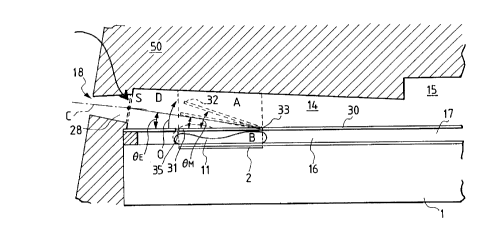
Fig. lO shows a schematic cross section, taken
along the direction of flow path, of the liquid
eJecting head of the present embodiment, and is a
drawing to show a relation among the maximum value 0,~ of
. 2175167
-- 51 --
the .1~ ~rl A~ t angle of the movable member, the
displacement angle ee of the straight line D r~nnF.(-:t~n~
the intersecting point S with the fulcrum of the
movable member with respect to the reference surface cf
5 the movable member, and an angle ec of the center axis C
in the direction of the droplet flying upon e~ection of
droplet with respect to the reference surface of the
movable member . The liquid e~ ecting head of this
embodiment is so arranged that the maximum ~li crl ~ t
angle e~, of the movable member is determined in the
range of 2~ - 7 s e~, < 2ee + 7 with respect to the
angle e of the straight line D connecting the
intersecting point S with the fulcrum portion of the
movable member from the reference surface of the
movable member by adjusting the th~ rkn~ of the
movable member or adj usting the height of the ceiling
of the first liquid flow path. The present embodiment
shows an example in which ee e 14 and e,, is thus
between 35 and 21 .
In the arrangement shown herein where the
movable member is displaced by the pressure based on
the bubble generated in the bubble generation region 11
by the heat generating element 2 and the movable member
31 guides the pressure toward the ejection outlet, it
is very important in respect of the liquid ejection
characteristics to ef f iciently direct the pressure
based on the bubble from the portion of the free end 32
~ 2175167
-- 52 -
displaced, of the movable member 31 toward the aperture
portion of the e~ection outlet 18 on the slde of the
first liquid flow path 14, as shown by Vl-V4 in Fig. 5,
by taking account of the relation between the
5 displacement angle o~ the movable member 31 and the
aperture portion on the side connected to the f irst
liquid flow path 14.
Namely, if the relation near ~IM = 2~,~ is
satisfied, the flow path configuration of the portlon
10 between the movable member in the maximum displacement
state and the reference surface becomes of line
~:;y L y with respect to a symmetry axis of the
straight line D, so that the central portion of
propagation of the pressure by the bubble is directed
15 straight to the center S of the aperture portion of the
e~ection outlet 18 on the flow path side. This
estRhl i ~hP~ propagation of the pressure and liquid flow
caused thereby without turbulence along the center axis
C of the eJ ection outlet portion, whereby the direction
20 of the liquid e~ected through the e~ection outlet 18 is
maintained in the very stable direction along the
direction of the center axis C. The stability of the
e~ection direction is thus remarkably imprQved by
satisfying the relation near ~3M = 2~E, whereby the shot
25 accuracy is enhanced on a printing sheet and
dist~lrhRn~P of quality of image is greatly reduced.
Here, the connecting portion between the
~ 21751~7
-- 53 --
e~ection outlet portion and the li~uid flow path means
a portion of a tubular portion ( in the configuration of
a cylindrical straight tube, a tapered tube, or a
curved tapered tube, which will be referred to as an
5 e~ection outlet portion) forming the ejection outlet
portion closest to the liguid flow path out of the
tubular portion forming the e~ection outlet, or a
portion near it.
Taking account of the variations or the like o~
10 the configuration of the ejection outlet when formed by
irradiation or the like with laser, the condition near
n = 2~ is determined to include the range of 2~ 7 '
S n S 2~, + 7~. A more preferable condition to enhance
the effect o~ the stability of the e~jection direction
15 discussed above is 2e~ - 5 s ~n S 2~ + 5~.
In addition to the above condition, the maximum
displacement ans~le G,~ of the movable member is e(Iual to
or more than the an~le of the straight line connecting
the fulcrum portion with the uppermost end of the
20 aperture of the ejection outlet portion connected to
the li~uid flow path 14, which is a preferable
condition for smooth propagation of pressure of the
bubble 40 and smooth ~low of the li~Iuid caused thereby.
Further, ~n is preferably determined within the
25 range of acute angles, ~ nsi~ring distortion or the
like of the fulcrum portion 33 of the movable member
31, and more preferably, is not more than 35. These
_ 54 _ 21 751 67
stipulations of the upper limit and the lower limit of
n are also applied to the other embodiments from the
same reasons.
( Embodiment 2 )
Next, Fig. 11 shows a schematic cross section,
taken along the direction of flow path, of the liquid
e~ecting head of the present embodiment and is a
drawing to show a relation among the maximum value ON of
the displacement angle of the movable member, the
displ ~,~ L angle e~ of the straight line D connecting
the fulcrum portion 33 of the movable member with the
intersecting point S with respect to the reference
surface of the movable member, and the angle c of the
center axis C in the direction of the liquid droplet
flying upon e jection o~ liquid droplet with respect to
the position of the reference surface of the movable
member. Here, the position of the fulcrum portion 33
is located near the cut end of the slit 35 in Figs. 9A-
9C, similarly as defined hereinbefore.
In this embodiment, the maximum disrl ~, ,t
angle n of the movable member was de~f~rmi nf~-l to be 15
by forming the movable member in the configuration
widened to the end in the fulcrum portion, as shown in
Fig. 15C, 250 ,um ( +5 ,um) long, 36 um wide, and 5 ,um
thick and made of Ni. Further, the height of the first
liquid flow path 14 was in the range of 40 ,um to 60 ,um
and the height of the second liquid flow path 16 was 15
- 55 - 2~ 751 ~7
,um in the present embodiment. However, ~ig. 11 shows
an e~ample in which the height of the first flow path
is 40 ,um. When the eJection outlet is formed by
irradiation with laser, the rli srl Al t angle ~,3 of the
straight line D connecting the fulcrum of the movable
member with the intersecting point S with respect to
the reference surface of the movable member 31 is
defined within the range of 5 to 7.5 (preferably 6 S
eE S 6.5 ) and it is formed to satisfy the relations of
eM = 2eE and 2eE < ~M s 2eE + 5. In this embodiment the
angle ec of the center axis C in the direction of the
li(auid droplet flying upon eJection of droplet with
respect to the non-displaced position of the movable
member 31 was det.orm i nl~l to be 10 . ~he driving
conditions of the head were the voltage of several V to
several ten V, the electric current of approximately
0 .1 to 0.2 A, and the pulse width of 1. 5 to 10 ,usec,
and the length L of the eJ ection outlet portion was
detl~rm~ nf~-l between 30 and 50 ,um.
To satisfy the condition near ~3M = 2~3E is also a
very important factor for st~h;li7~tion of eJection
direction in the present embodiment, similarly as in
the previous embodiment.
As a further method for maintaining this state
in the ejection operation period for a longer time, the
movable member 31 may be operated so as to exceed eM
satisfying eM = 2eE. Arranging to satisfy the relation
- 56 - 21751b7
of 2a~ < eM < 2eE + 5, this arrangement attained
stabilization of e~ection direction and stabler
ejection efficiency. Further, this also improved
stabilization of eJection state against variations of
the conf iguration of e j ection outlet as discussed
previously .
A further preferable condition is to satisfy
the condition near the center of the relation of 2e~ <
2e~ + 5 ( 6 ~ e~ < 6 . 5 in the present embodiment ) .
Another means for satisfying this relation of 2e~ = e~,
is to provide a part of the wall of the first flow path
14 with a control portion 57 of the maximum
diSr~ angle 0,q as shown in Fig. 16.
( Embodiment 3 )
Fig. 12 shows a schematic cross section, taken
along the direction of flow path, of the liquid
ejecting head of the present embodiment, similar to
those of Embn-l; L~i 1 and 2, and is a drawing to show
a relation among the maximum value e" of the
displ ~- ~ angle of the movable member, the
disrl ;~1 t angle e~ of the straight line D connecting
the fulcrum of the movable member with the intersecting
point S with respect to the natural position of the
movable member, and the angle ~c of the center axis C in
the direction of the liquid droplet flying upon
ejection of droplet with respect to the natural
position of the movable member . The liquid ej ecting
~ _ 57 _ 2 1 7 5 1 67
head of this embodiment has the structure similar to
that of Embodiment 1, but the maximum fl1 .crl Arl -t
angle e" of the movable member is de~rmi n~A to be
approximately 20 by decreaslng only the th 1 rkn~Rc of
5 the movable member in the prevlous ~mhr~fl ~ t to 3 . 5
,um. The dlsplacement angle et of the straight line D
connecting the fulcrum of the movable member with the
intersecting point S with respect to the natural
position of the movable member is determined within the
range of 10 to 12.5 (preferably 11' e,S 5 12 ) upon
formation of e~ection outlet by the aforementioned
method, and it is ~L~ y~d to satisfy the relation of e~
= 2e~ or 2ee > ~" 2 2ee - 5. In this embodiment the
angle ec of the center axis C in the direction of the
15 droplet flying upon ejection of droplet with respect to
the natural position of the movable member was
detf~rm1 n~fl to be 25 ( the value of L is the same as ln
Embodiment l ) . Further, the height of the second
liquld flow path 16 was the same as ln previous
20 Embodiment 1 and the height of the first flow path was
between 40 ,um and 80 ,um in the present embodiment.
E~owever, Fig. 12 shows an example in which the height
of the first liquid flow path 14 is 60 ,um. ~he driving
conditions are also the same as those in the previous
25 embodiments.
When the relation of e,~ = 2eE is satisfied in
the present embodiment, the stability of e~ection
2175167
-- 58 --
direction is also improved similarly as in ~mbodiments
1, 2 stated above.
Also in the case of the relation of 2eE > en 2
2e~ - 5 being satisfied, the effect is attained to
5 5t;1hl11 ~e the e~ection state caused by variations or
the like of the configuration of ejection outlet as
described previously.
A preferable condition to further improve such
an effect is to satisfy the condition near the center
of 2eE > eM 2 2eE - 5 ( 11 < eE 12 in the present
embodiment ) . Also in the case of the present
embodiment another means for satisfying the relation of
(3E and e~, is to provide a part of the wall of the f irst
flow path 14 with a control portion 57 of maximum
15 displacement angle ~,~, as shown in Fig. 16.
Further, ~" is del~ormi n~l in the range of acute
angles, mmncl(l~ing the fulcrum portion 33 of the
movable member 31. Fig. T3 shows an example in which e"
is 28 and ~3E is 14', which achieved the same effects as
20 described above.
As shown in each embodiment described above,
the free end can be smoothly displaced by setting the
height of the ceiling of the flow path communicating
with the e~ection outlet higher on the free end side of
25 the movable member than on the fulcrum side.
Each of ~mbodiments 1 to 3 described above has
the oonfiguration of the bubble generation flow path
_ 59 _ 2175167
shown in Figs. 9A to 9C where the throat portions 19
narrowed in the direction of arrangement of a plurality
of bubble generation flow paths arranged in parallel
are positioned near the upstream end and the downstream
5 end of the second liquid flow path, but they may be
located near the upstream end and the downstream end of
the vicinity of the heat generating element 2.
The heat generating element 2 is an
electrothermal tr~ncd~ ~r in the conf iguration of 40 x
105 ,um ana the movable member 31 is positioned so as to
cover the af orementioned chamber in which the heat
generating element 2 is disposed. The size,
configuration, and location of the heat generating
element 2 or the movable member 31 are not limited to
15 these, but the configuration and location may be
detF~rmi n~rl within the range where the pressure upon
generation of bubble can be effectively utilized as an
e~ ection pressure. The heat generating element may be
an element for generating heat when irradiated with
20 laser light, as well as the electrothermal transducer.
( Other embodiments )
In the foregoing, the description has been made
as to the embodlments of the maj or parts of the liquid
e~ectlng head and the liquid ejectin~ method according
25 to the present invention. Further specific examples
preferably applicable to these embodiments will be
explained with reference to tlle drawings. Although the
- 60 - 2 1 7 5 1 67
following ~ q will be explained with either an
embodiment of the slngle-f low-path type or an
embodiment of the two-flow-path type described
previously, it should be noted that they can be applied
5 to the both embodiments unless otherwise stated.
( Movable member and partition wall )
Figs. 15A, 15B, and 15C are plan views to show
other configurations of the movable member 31, whereln
reference numeral 35 designates the slit formed in the
10 partition wall and this slit forms the movable member
31. Fig. 15A illustrates a rectangular configuration,
Fig. 15B a confi~uration narrowed on the fulcrum side
to facilitate the operation of the movable member, and
Fig. 15C a configuration widened on the fulcrum side to
15 enhance the durability of the movable member. The
configuratlon of the movable member may be any
configuratlon readlly operable and l~xr.~ nt in the
durabil i ty .
In the foregolng embodiments, the plate movable
20 member 31 and the partition wall 30 having this movable
member were made of nickel in the thi rknf ~c~ of 5 ,um,
but, without having to be limited to this, the
materials for the movable member and the partitlon wall
may be selected from those having anti-solvent property
25 against the bubble generation liquid and the ejection
liquid, having elastlclty for assuring the satisfactory
operation of the movable member, and permitting
- 61 - 2175167
formation of fine slit.
Preferable examples of the material for the
movable member include durable materials, for example,
metals such as sllver, nickel, gold, iron, titanium,
~1 ~n~lm, platinum, tantalum, stainless steel, or
phosphor bronze, alloys thereof, resin materials, for
example, those having the nitryl group such as
acrylonitrile, butadiene, or styrene, those having the
amidle group such as polyamide, those having the
10 carboxyl group such as polycarbonate, those having the
aldehyde group such as polyacetal, those having the
sulfone group such as polysulfone, those such as liquid
crystal polymers, and chemical compounds thereof: and
materials having durability against the ink, for
15 example, metals such as gold, tungsten, tantalum,
nickel, stainless steel, titanium, alloys thereof,
materials coated with such a metal, resin materials
having the amide group such as polyamide, resin
materials having the aldehyde group such as polyacetal,
20 resin materials having the ketone group such as
polyetheretherketone, resin materials having the imide
group such as polyimide, resin materials having the
hydroxyl group such as phenolic resins, resin materials
having the ethyl group such as polyethylene, resin
25 materials having the alkyl group such as polypropylene,
resin materials having the epoxy group such as epoxy
resins, resin materials having the amide group such as
- 62 - 2 1 7 5 1 67
r~l~minP resins, resin materials having the methylol
group such as xylene resins, chemlcal compounds
thereof, ceramlc materials such as silicon dioxide, and
l-hPm~-~l compounds thereof.
Preferable P _ 1 P~: of the material for the
partition wall include rOEin materials having high
heat-resistance, high anti-solvent property, and good
moldability, typified by recent engineering plastics,
such as polyethylene, polypropylene, polyamide,
10 polyethylene terephthalate, - l r nP resins, rhPn~
resins, epoxy resins, polybutadiene,
polyetheretherketone, polyether sulfone, polyallylate,
polyimide, polysulfone, liquid crystal polymers ( LCPs ),
rhPm;~'Rl compounds thereof, silicon dioxide, silicon
15 nitride, metals such as nickel, gold, or stainless
steel, alloys thereof, ~hPml~'Rl compounds thereof, or
materlals coated with titanium or gold.
The th; ~knPcc of the partition wall may be
de~PrminP~l ~lPrPn~n~ upon the material and
20 configuration from such standpoints as to achieve the
strength as a partition wall and to well operate as a
movable member, and a desirable range thereof is
approximately between 0. 5 ,um and 10 ,um.
The width of the slit 35 for forming the
25 movable member 31 is de~Prm~ nP~ to be 2 ,um in the
present embodiment. In the cases where the bubble
generation liquid and the e~ection liquid are mutually
- 63 - 2~75~67
different liquids and mixture is prevented between the
two liquids, the slit width may be determined to be a
clearance to form a meniscus between the two liquids so
as to avoid communication between the two liquids. For
5 example, when the bubble generation liquid is a liquid
having the vlscoslty of about 2 cP ( centipoises ) and
the ejection liquld is a liquid having the viscosity of
100 or more cP, a slit of approximately 5 ,um is enough
to prevent the mixture of the liquids, but a desirable
10 slit is 3 or less ,um.
In the present invention the movable member is
intended to have a ~hi~-kn~R of the ,um order (t ,um),
but is not intended to have a thlckness of the cm
order For the movable member ln the ~h~kn~q~: of the
15 ,um order, it is deslrable to take account of the
varlatlons ln fabrication to some extent when the slit
width of the ,um order ( W ,um ) is targeted .
The slit of such several ,um order is surer to
accomplish the "substantially sealed state" in the
20 present invention.
In the case of the functional separation into
the bubble generation liquid and the ejection liquid as
described above, the movable member is a substantially
separating member for separating them. When this
25 movable member moves with generation of bubble, a small
amount of the bubble generation liquid appears mixing
into the e~ection liquid. Considering that the
- 64 - 2 ~ 7 5 ~ 6 7
ef ection liquid for forming an image is usually one
having the concentration of coloring material ranging
approximately 3 % to 5 % in the case of the ink ~ et
recording, a great change in the concentration will not
5 be resulted even if the bubble generation liquid is
contained in the range of 20 or less % in a droplet of
the e~ection liquid. Therefore, the present invention
is intended to involve mixture of the liquids between
the bubble generation liquid and the e~jection liquid as
10 long as the mixture is limited within 20 % of the
bubble generation liquid in the droplet of the e~ection
liquid .
In carrying out the above structural , 1~,
the mixture was at most 15 % of the bubble generation
15 liquid even with changes of the viscosity, and with the
bubble generation liquid of 5 or less cP the mixture
rate was at most approximately 10 %, though rlPr~n~l;
upon the driving frequency.
Particularly, as the viscosity of the e~ection
20 liquid is decreased below 20 cP, the mixture of the
liquids can be decreased more ( for example, down to 5
or less % ) .
( Element substrate )
Next explained is the configuration of the
25 element substrate in which the heat generating element
for supplying heat to the liquid is mounted.
Figs. 17A and 17B show longitudinal sectional
~ - 65 - 2 ~ 75 ~ 67
views of the liquid e~ecting heads according to the
present invention, wherein Fig. 17A shows the head wlth
a protection film as detailed hereinafter and Fig. 17B
the head without a protection film.
Above the element substrate 1 there are
provided the second liquid flow path 16, the partition
wall 30, the first liquid flow path 14, and a grooved
member 50 having a groove for forming the first liquid
flow path.
The element substrate l has patterned wiring
electrodes (0.2-1.0 ,um thick) of aluminum (Al) and
patterned electric reslstance layer 105 ( 0 . 01-0 . 2 ,um
thlck) of hafnlum borlde (HfB2), tantalum nltride (TaN),
tantalum All~m1nllm (TaAl) or the llke constitutlng the
heat generatlng elements on a sllicon oxide film or
silicon nitride film 106 for electric insulation and
thermal A( 1 Ation formed on the substrate 107 of
silicon or the like, as shown in Fig. 8. The
resistance layer generates heat when a voltage is
applied to the resistance layer 105 through the two
wiring electrodes 104 so as to let an electric current
flow in the resistance layer. A protection layer of
SiO2, SiN, or the like 0.1-2. 0 um thick is provided on
the resistance layer between the wiring electrodes, and
in addition, an anti-cavitation layer of tantalum or
the like ( 0 .1-0 . 6 um thick ) is formed thereon to
protect the resistance layer 105 from various liquids
- 66 - 2 1 7 5 1 6 7
such as ink.
Particularly, the pressure and shock wave
generated upon bubble generation and collapse is so
strong that the durability of the oxide film hard and
relatively fragile is r~f~n~ ~lPrably deteriorated.
Therefore, a metal material such as tantalum (Ta) or
the like is used as a material for the anti-cavitation
layer .
The protection layer stated above may be
omitted ~'iPrPn~ n~ upon the combination of liquid,
liquid flow path structure, and resistance material, an
example of which is shown in Fig. 17B. The material
for the resistance layer not requiring the protection
layer may be, for example, an iridium-tantalum-aluminum
( Ir-Ta-Al ) alloy or the like.
Thus, the structure of the heat generating
element in each of the foregoing em~odiments may
include only the resistance layer ( heat generating
portion ) between the electrodes as described, or may
include a protection layer for protecting the
reslstance layer.
In this embodiment, the heat generating element
has a heat generation portion having the resistance
layer which generates heat in response to the electric
signal Without having to be limited to this, any
means well suffices if it creates a bubble enough to
e ject the e~ection liquid, in the bubble generation
-67- 2~75167
liquid. For example, the heat generation portion may
be in the form of a photothermal transducer which
generates heat upon receiving light such as laser, or a
heat generating element having the heat generation
5 portion which generates heat upon receiving high
frequency wave.
Function P~ such as a transistor, a
diode, a latch, a shift register, and so on for
selectively driving the electrothermal transducer may
10 also be integrally built in the aforementioned element
substrate 1 by the semiconductor f abrication process,
in addition to the electrothermal transducer comprised
of the resistance layer 105 constituting the heat
generating element and the wiring electrodes 104 for
supplying the electric signal to the resistance layer. ~=
In order to drive the heat generation portion
of the electrothermal tr~nc~ r on the above-described
element substrate 1 so as to e~ect the liquid, a
rectangular pulse as shown in Fig. 18 is applied
20 through the wiring electrodes 104 to the aforementioned
resistance layer 105 to quickly heat the resistance
layer 105 between the wiring electrodes. With the
heads of the foregoing embodiments, the electric signal
was applied to each at the voltage 24 V, the pulse
25 width 7 ,usec, the electric current 150 mA, and the
frequency 6 kHz to drive the heat generating element,
whereby the ink as a ~ iquid was e l ected through the
,~ 2175167
68
ej ection outlet, based on the operation descrlbed
above. ~owever, the conditions of the driving signal
are not limited to the above, but any driving signal
may be used if it can properly generate a bubble in the
5 bubble generation liquid.
(Ejection liquid and bubble generation liquid)
Since the present invention employs the
structure having the aforementioned movable member as
discussed in the previous embodiments, the liquid
10 e~ectlng head according to the present invention can
eject the liquid at higher e~ection power, at higher
e;~ection efficiency, and at higher speed than the
conventional liquid ej ecting heads can . In the cases
of the same liquid being used for the bubble generation
liquid and the e~ection liquid in the present
embodiment, the liquid may be selected from various
liquids as long as it is unlikely to be deteriorated by
the heat applied by the heat generating element, it is
unlikely to form a deposit on the heat generating
20 element with application of heat, it is capable of
undergoing reversible state changes between
gasification and condensation with application of heat,
and it is unlikely to deteriorate the liquid flow
paths, the movable member, the partition wall, and so
25 on.
Among such liquids, the liquid used for
recording ( recording liquid ) may be one of the ink
- 69 - 2 ~ 7 5 1 6 7
liquids of compositions used in the conventional bubble
jet devices.
When the two-flow-path structure of the present
invention is used with the e~ection liquid and the
5 bubble generation liquid of different liquids, the
bubble generation liquid may be the liquid having the
above-mentioned properties; specifically, it may be
selected rom methanol, ethanol, n-propanol,
isopropanol, n-hexane, n-heptane, n-octane, toluene,
10 xylene, methylene dichloride, trichlene, Freon TF,
Freon BF, ethyl ether, dioxane, oy~ hPXAn~, methyl
acetate, ethyl acetate, acetone, methyl ethyl ketone,
water, and mixtures thereof.
The e~ection liquid may be selected from
15 various liquids, free from possession of bubble
generation property and thermal property thereof.
Further, the e~ection liquid may be selected from
liquids with low bubble generation property, e~ection
of which was difficult by the conventional heads,
20 liquids likely to be modified or deteriorated by heat,
and liquids wlth high viscosity.
However, the e~ection liquid is preferably a
liquid not to hinder e jection of liquid, generation of
bubble, the operation of the movable member, and so on
25 because of the ejectlon liquid itself or because of a
reaction thereof with the bubble generation liquid.
For example, a high-viscoslty ink may be used
~ - 70 ~ 2175167
as the eJectlon liquid for reeording. Other e~ectlon
liquids applicable includes liquids weak against heat
such as pharmaceutical products and perfumes.
In the present invention recording was carried
5 out using the ink liquid in the following composition
as a recording liquid usable for the both e~eetion
liquid and bubble generation liquid. Since the
e~eetion spee~ of ink is increased by an ~ ,llUV. t in
the e~ection power, the shot accuracy of liquid
lO droplets is improved, which enables to obtain very good
recording images.
Composition of dye ink (viscosity 2 cP)
( C I . hood black 2 ) dye 3 wt96
Diethylene glycol 10 wt~6
15Thio diglyeol 5 wt%
Ethanol 5 wt~6
Water 77 wt96
Further, recording was also carried out with
combinations of liquids in the following compositions
for the bubble generation liquid and the e~ection
liquid. As a result, the head of the present invention
was able to well e~ect not only the liquid with the
viscosity of ten and several cP, which was not elected
by the conventional heads, but also even a liquid with
a very high viscosity of 150 cP, thus obtaining high-
quality recorded ob lects.
Composition of bubble generation liquid 1
- 71 - 21 751 67
Ethanol 40 wt%
Water ~ 60 wt%
Composition of bubble generation liquid 2 .
Water 100 wt%
Composition of bubble generation lilluid 3
Isopropyl alcohol lO wt%
Water 90 wt%
Composition of pigment ink of eJ ection li~uid
(viscosity approximately 15 cP)
Carbon black 5 wt%
Styrene-acrylic acid-ethyl acrylate copolymer
1 wtg6
( acid value 140 and weight average molecular
weight 8000 ) ~:
15 Monoethanol amine 0 . 25 wt %
Glycerine 69 wt%
Thio diglycol 5 wt%
Ethanol 3 wt%
Water :.: 16 . 75 wt%
Composition of eJection li~uid 2 (viscosity 55 cP)
Polyethylene glycol 200 I00 wt%
Composition of eJection li~uid 3 (viscosity 150 cP)
Polyethylene glycol 600 100 wt%
Incidentally, wi~h the li~uids conventionally
considered as not readily be eJected as described
above, the shot accuracy of dots was poor on the
recording sheet because of the low eJ ection speed and
~ 2175167
-- 72 --
increased variations in the eJection directionality,
and unstable eJection caused variations o e~ection
amounts, which made it .l; f f;, l t to obtain high-quality
images. Against it, the structures of the above
embodiments realized satisfactory and stable generation
of bubble using the bu~le generation liquid. This
resulted in an illlL~lUv~ t in the shot accuracy of
droplets and stabilization of ink e~ection amounts,
thereby remarkably improving the quality of recording
images.
(Structure of head of two-flow-path type)
Fig. 19 and Fig. 20 are a sectional view and an
exploded, perspective view, respectively, to show the
structure of the whole of the head of the two-flow-path
type out of the liquid e~jecting heads of the present
invention .
The af orementioned element substrate 1 is
mounted on a support 70 of aluminum or the like. ûn
the substrate there are provided walls 16a of the
second liquid flow path 16 and walls 17a of the second
common liquid chamber 17, on which the partition wall
30 having the movable member 31 i8 mounted. On this
partition wall 30 there is provided a grooved member 50
having a plurality of grooves constituting the f irst
liquid flow paths 14, the first common liquid chamber
15, a supply passage 20 for supplying the first liquid
to the first common liquid chamber 15, and a supply
. ~ 2175167
-- 73 --
passage 21 for supplying the second liquid to the
second common liquid chamber 17. The liquid e~ecting
head of the two-flow-path type is constructed in this
structure .
( Liquid e ~ ection head cartrldge )
Next PYrlf~1nPrl schematlcally is a liquid
e~ ection head cartridge incorporating the liquid
e~ecting head according to the above embodiment.
Fig. 21 is a schematically exploded,
10 perspective view of the liquid e~ection head cartridge
incorporating the liquid eJecting head as described
above. The liquid e~ection head cartridge is generally
composed mainly of a liquid e~ecting head portion 200
and a liquid container 90.
The liquid e~ecting head portlon 200 comprises
an element substrate 1, a partition wall 30, a grooved
member 50, a presser bar spring 60, a liquid supply
member 80, and a support member 70. The element
substrate l is provided with a plurality of arrayed
heat generating resistors for supplying heat to the
bubble generation liquid, as described previously.
Further, there are provided a plurality of function
elements for selectively driving the heat generating
resistors. Bubble generation liquid passages are
formed between the element substrate 1 and the
aforementioned partition wall 30 having the movable
walls, thereby allowing the bubble generation liquid to
_ 74 _ 2~75~67
flow therein. This partition wall 30 is ~oined with
the grooved member 50 to form e~ ection f lo~ paths ( not
shown) through which the e~ectlon liquld to be e~jected
f lows .
The presser bar spring 60 is a member which
acts to exert an urging force toward the element
substrate l on the grooved member 50, and this urging
force properly incorporates the element substrate 1,
the partition wall 30, the grooved member 50, and the
support member 70 detailed below.
The support member 70 is a member for
supporting the element substrate l etc. Mounted on
this support member 70 are a circuit board 71 connected
to the element substrate 1 to supply an electric signal
thereto, and contact pads 72 connected to the apparatus
side to effect communication of electric signals with
the apparatus side.
The liquid container 90 separately contains the
e~ ection liquid such as lnk to be supplied to the
liquid e~ecting head and the bubble generation liquid
for generation of bubble inside. Outside the liquid
container 90 there are a positioning portion 94 for
positioning a connecting member for connecting the
liquid e~ecting head with the liquid container, and a
fixed shaft 95 for fixing the connection portion. The
e~ection liquid is supplied from an e~ection liquid
supply passage 92 of the liquid container through a
` ~ 2175167
-- 75 --
supply passage of the connecting member to an e~ ection
liquid supply passage 81 of the liquid supply member 80
and then is supplied through e~ection liquid supply
passages 84, 61, 20 of respective members to the first
common liquid chamber. The bubble generation liquid is
similarly supplied from a supply passage 93 of the
liquid container through a supply passage of the
connecting member to a bubble generation liquid supply
passage 82 of the liquid supply member 80 and then is
supplied through bubble generation liquid supply
passages 84, 61, 21 of respective members to the second
liquid chamber .
The above liquid e l ection head cartridge was
explained with the supply mode and liquid container
permitting supply of dif ferent liquids of the bubble
generation liquid and the e~ection liquid, but, if the
e~ection liquid and the bubble generation liquid are of
the same liquid, there is no need to separate the
supply passageæ and container for the bubble generation
liquid and the eJection liquid.
This liquid container may be refilled with a
liquid after either liquid is used up. For this
purpose, the liquid container is desirably provided
with a liquid injection port. The liquid e~ecting head
may be arranged as integral with or separable from the
liquid container.
( Liquid eJ ecting device )
- 76 _ 2 1 7 5 1 6 7
Fig. 22 shows the schematic structure of the
liquid eJecting device incorporating the liquid
ejecting head descrlbed previously. The present
embodiment will be P~-rl~1nP~ especially with an ink
eJection recording apparatus using the ink as the
e~ ection liquid . A oarriage HC of the liquid eJ ecting
device carries a head cartridge on which a liquid tank
portion 90 containing the ink and a liquld e~ection
head portion 200 are detachably mounted, and
L0 reciprocally moves widthwise of a recording medium 150
such as a recording sheet conveyed by a recording
medium conveying means.
When a driving signal is supplied from a
driving signal supply means not shown to the liquid
e~ecting means on the carriage, the recording liquid is
e~ ected ~rom the liquid e ~ ecting head to the recording
medium in response to this signal.
The liquid ej ecting apparatus of the present
embodiment has a motor 111 as a driving source for
driving the recording medium conveylng means and the
carriage, and gears 112, 113 and a carrlage shaft 115
ior transmlttlng the power from the drlvlng source to
the carrlage. By this recording apparatus and liquid
ej ecting method therewlth, recorded artlcles wlth good
images were able to be attalned by e~ectlng the llquid
to various recording media.
Fig. 23 is a block diagram of the entire
_ 77 2175167
apparatus for operating the ink e~ecting apparatus to
which the liquid e jecting method and li~uid e~ecting
head of the present invention are applied.
The recording apparatus receives printing
5 information as a control signal from a host computer
300. The printing information is temporarily stored in
an input interface 301 inside a printing apparatus,
and, at the same time, is converted into data
processable in the recording C~ LCI~US. This data is
10 input to a CPU 302 also serving as a head driving
signal supply means. The CPU 302 processes the data
thus received, using peripheral units such as RAM 304,
based on a control program stored in ROM 303 in order
to convert the data into printing data ( image data ) .
In order to record the image data at an
L~ iate position on a recording sheet, the CPU 302
generates driving data for driving the driving motor
for movlng the recording sheet and recording head in
synchronization with the image data. The image data
20 and motor driving data is transmitted each through a
head driver 307 and a motor driver 305 to a head and a
drive motor 306, respectively, which are driven at
respective controlled timings to form an image.
Fx;~mrl ~c of the recording media applicable to
25 the above recording apparatus and recorded with the
li~auid such as ink include the following: various types
of paper; OHP sheets; plastics used for compact disks,
~ 2~75167
-- 78 --
ornamental plates, or the like; fabrics; metals such as
aluminum and copper; leather materials such as cowhide,
pigskin, and synthetic leather; lumber materials such
as solid wood and plywood; bamboo material; ~
such as tile; and three-~ nn~l structures such as
Sponge .
The aforementioned recording apparatus includes
a printer apparatus for recording on various types of
paper and OHP sheet, a plastic recordlng apparatus for
10 recording on a plastic materlal such as a compact disk,
a metal recording apparatus for recording on a metal
plate, a leather recording apparatus for recording on a
leather material, a wood recording apparatus for
recordlng on wood, a ceramic recording apparatus for
15 recording on a ceramic material, a recording apparatus
for rf~rnr-l1n~ on a three-~ 1nn;l1 network structure
such as sponge, a textile printing apparatus for
recording on a fabric, and so on.
The ef ection liquid used in these liquid
20 efecting a~lc.l,us may be properly selected as a liquid
matching with the recording medium and recording
conditions employed.
(Recording system)
Next explained is an example of the ink f et
25 recording system using the li~uid ejecting head of the
present invention as a recording head and performing
recording on a recording medium.
2t75167
-- 79 --
Flg. 24 is a schematic drawing for explaining
the structure of the ink ~et recording system using the
liquid e~ecting head 201 of the present inventlon
described above. The liquid e ~ ectlng head in the
5 present embodiment is a full-line head having a
plurality of e ~ ection outlets aligned in the denslty of
360 dpi so as to cover the entire recordable range of
the recording medium 150. The liguid e~ecting head
comprises four head units corresponding to four colors
10 of yellow (Y), magenta (M), cyan (C), and black (Bk),
which are fixedly supported ln parallel with each other
and at predetPrm i nPfl intervals in the X-direction.
A head driver 307 constituting a driving signal
supply means supplies a signal to each of these head
15 units to drive each head unit, based on this signal.
The four color inks of Y, M, C, and 8k are
supplled as the e~ection li~uid to the associated heads
from corresponding ink containers 204a-204d. Reference
numeral 204e designates a bubble ~eneration li(auid
20 container containing the bubble generation li~auid, from
which the bubble generation li~auid is supplied to each
head unit.
Disposed below each head is a head cap 203a,
203b, 203c, or 203d containing an ink absorbing member
25 comprised of sponge or the like inside. The head caps
cover the e~ ection outlets of the respective heads
during non-recording periods so as to protect and
2~75167
-- 80 --
maintain the head units.
Reference numeral 206 denotes a conveyer belt
constituting a conveying means for conveying a
recording medium selected from the various types of
5 media as explained in the preceding embodiments. The
-v~y~r belt 206 is routed in a predet~rml nP-l path via
various rollers and is driven by a driving roller
connected to a motor driver 305.
The ink ~ et recording system of this embodiment
lO comprises a pre-prnr~q~ n~ apparatus 251 and a post-
processing apparatus 252, disposed upstream and
downstrearn, respectively, of the recording medium
conveying path, for effecting various processes on the
recording medium before and after recording.
The pre-processing and post-processing may
include different processing contents depending upon
the type of recording medium and the type of ink used
in recording. For example, when the recording medium
is one selected from metals, plastics, and ceramics,
20 the pre-processing may be ~L)Ob;U1~ to ultraviolet rays
and ozone to actlvate the surface thereof, thereby
improving nllh-~cl ~n of ink. If the recording medium is
one likely to have static electricity such as plastics,
dust is easy to attach to the surface because of the
25 statl c electricity, and this dust sometimes hinders
good recording. In that case, the pre-pro~m~1 n~ may
be elimination of static electricity in the recording
2 1 75 ~ 67
-- 81 --
medium using an ionizer, thereby removing the dust from
the recording medium. If the recording medium is a
~abric, the pre-processing may be a treatment of
application of a material selected from ~lk~l inP
substances, water-soluble substances, synthetic
polymers, water-soluble metal salts, urea, and thiourea
to the fabrlc in order to prevent blot and to improve
the deposition rate. The pre-processing does not have
to be limited to these, but may be any processing, for
example processing to ad~ust the temperature of the
recording medium to a temperature suitable for
recording .
On the other hand, the post-processing may be,
for example, heat processing of the recording medium
with the ink deposited, fixing processing for promoting
fixation of the ink by irradiation with ultraviolet
rays or the like, prnrP~lnS for washing away a
treatment agent given in the pre-processing and
1~ lnln~ without reacting.
The present embodiment was Pxrl~inP~l using the
full-line head as the eJecting head, but, without
having to be limited to this, the head may be a compact
head for effecting recordin~ as moving in the widthwise
direction of the recording medium, as described
previously.
( Head kit )
Next P-rrl~lnP.l is an ink ~et head kit having
2175167
-- 82 -
the ink j et head of the present invention. Fig . 25 is
a schematlc drawing to show such an ink ~ et head kit .
This ink ~ et head kit is composed of an ink j et head
510 of the present invention having an ink e~ ection
portion 511 for e~ecting the ink, an ink container 520
as a liquid container integral with or separable from
the head, and an ink filling means 530 containing the
ink to fill the ink in the ink container, housed in a
kit container 501.
After the ink is used up, a part of an
inj ection portion ( hypodermic needle or the like ) 531
of the ink filling means 530 is inserted into an air
vent 521 of the ink container, a connecting portion to
the ink jet head, or a hole perforated through an wall
of the ink container, and the ink in the ink f illing
means is filled into the ink container through the
inj ection portion .
Employing the arrangement of the kit housing
the ink jet head of the present invention and the ink
container and ink filling means in a single kit
container in this manner, the ink can be readily filled
in the ink container soon af ter the ink is used up, and
recording is restarted quickly.
Although the ink j et head kit of the present
embodiment was p~rrl~in~fl as an ink jet head kit
l n~ fl ~ n~ the ink f illing means, it may be constructed
without the ink filling means in an arrangement of the
r
2175167
- 83 -
head and the ink container of a separable type filled
with ink, housed in the kit container 510.
Fig. 25 shows only the ink filling means for
filling the ink into the ink container, but another
head kit may also have a bubble generation liquid
filling means for filling the bubble generation liquid
into the bubble generation liquid container, in the kit
container, as well as the ink container.
The present invention ~ hF~-l the further
more stabilized ejection state of liquid by properly
specifying the maximum displacement angle when the
movable member, fundamentally controlling the bubble
generated in the liquid flow path, is 11 c~ 1 at
maximum by generation of bubble with respect to the
angle of the straight line connecting the fulcrum
portion of the movable member with the lntersecting
point of the center axis of e ~ ection outlet with the
surface of the e~ection outlet connected to the liquid
flow path from the reference of the standby position of
the movable member. Particularly, the present
invention solved the problem of variations of e~ection
state due to variations of configuration of e~ectlon
outlet between heads or between nozzles caused by the
factor of manufacturing varlations in forming the
e~ection outlet with laser or the like, thereby
achieving very high stability.
In addition to the above-described effects, the
~ ~ 2175167
-- 84 --
li(Iuid e~ecting method, head, and 80 on according to
the present invention, based on the novel election
principle using the movable member, can attain the
synergistic effect of the bubble generated and the
5 mcvable member displaced thereby, so that the liS!uid
near the e~ection outlet can be Pffir1~ntly e~ected,
thereby improving the e~ ection ef f iciency as compared
with the conventional e~j ection methods, heads, and so
on of the bubble ~ et method .
With the characteristic structures of the
present invention, e~ection failure can be prevented
even after long-term storage at low temperature or at
low moisture, or, even if e~ectlon failure occurs, the
head can be advc~ ay~ :ously returned instantly into a
normal condition only with a recovery process such as
prPl 1m~n;~ry e~ection or suction recovery. With this
advantage, the invention can reduce the recovery time
and losses of the liquid due to recovery, and thus can
greatly decrease the running cost.
F:qpF.r.1 F~ 1 1 y, the structures of the present
invention improving the ref illing characteristics
attained ~, .,v, ts in responsivity upon continuous
e;jection, stable growth of bubble, and stability of
li(auid droplet, thereby c.n;~hl ~ ng high-speed recording
2~ or high-quality recording based on high-speed liguid
e~ ection .
In the head of the two-flow path structure the
2175167
-- 85 --
freedom of selection of the e~ection liquid was raised
because the bubble generation liquid applied was a
liquid likely to generate a bubble or a liquid unlikely
to f orm a deposit ( scorch or the like ) on the heat
generating element. It was ct~nf; ~l that the head of
the two-flow path structure was able to well e~ject even
the liquid that the conventional heads f ailed to e~ ect
in the conventional bubble jet eJection method, for
example, a high-viscoslty liquid unlikely to generate a
bubble, a liquid likely to form a deposit on the heat
generating element, an so on.
Further, lt was conf irmed that the head of the
two-flow path structure was able to eject even a liquid
weak against heat or the like without causing a
negative effect on the e~ection liquid.
When the liquid e~ecting head of the present
inventlon was used as a liquid e~ ection recording head
for recording, further higher-quality recording was
achieved .
The invention provided the liquld e~ ecting
apparatus, recording system, and so on further improved
ln the e~ection efficlency of liquid or the like, uslng
the liquid e~ ecting head of the present invention.
Use or reuse of the head can be readily
achieved using the head cartridge or the head kit of
the present invention.