Note: Descriptions are shown in the official language in which they were submitted.
PCT/NL 93/002.14 21 l 5 i 8 9
The present invention relates to a hose belt conveyor according
to the preamble of claim 1
Such a hose belt conveyor is known from the German
Offenlegungsschrift 4,036,731. To drive the adjacent thickened parts the
abutting sides are provided with opposed recesses to accommodate a wire
structure comprising two interconnected wires. These wires have to
transmit driving forces.
This structure is relatively complicated but necessary to
guarantee sufficient drive for the thickened parts.
From the British patent~application 2,007,t78 a hose belt
conveyor is known wherein the thickened parts are trapezium-shaped. When
these thickened parts lie against each other, a V is formed with an angle
greater than 120°. The two parts of the V may be supported on rollers,
as
shown in Fig. 3 of this British Patent Specification. It is necessary
here for the thickened parts to be pressed against each other, and this
_ is achieved by making the rollers stepped. The first part acts upon the
above-described V-forming part, while the second part of the rollers
connects to the top side of the trapezium of each of the thickened parts.
This means that the rollers have to be of relatively complex design and
that a considerable measurement tolerance is necessary. If the distance
between the parallel outsides of the thickened parts is reduced through
wear, it will be necessary to adapt the spacing of tze raised sides of
the rollers. For this purpose, it is necessary to provide for the rollers
to move relative to one another. In the case of the design according to
this British Patent Specification, the drive is by means of a pair of
rollers which enclose the trapezium-
Substitute sheet dated August 18, 1995
AMENDED SHEET
2175189
.. -2-
shaped thickened part on all sides. Such a drive is relatively complex
and, as in the case of conventional conveyor belts, is generally provided
at only one place. This makes it necessary for the belt to be provided
with longitudinal reinforcements for absorbing the driving forces
produced by the single drive motor and extending over the length of the
belt. Such a drive also means that the length of such belts is limited,
because the driving forces would otherwise becbme too great for the
longitudinal reinforcement, or because otherwise the belt becomes
expensive.
From the PCT-application 93/08107 a hose belt conveyor is known
wherein the sides abutting each other are perpendicular to the extension
of the hose belt. It is not possible to clamp the thickened parts between
two V-shaped driving or guiding members.
The invention aims to provide a more simplified design for hose
belt conveyors.
This object is realized with the characterizing features of
claim 1.
The invention is based on the idea that the two thickened parts
should be designed in such a way that if they are placed against each
other a V is produced, more or less corresponding to the V used in belt
drives. It has also been found that if the angle range according to the
invention is used, the two thickened parts do not have the tendency to
slide past each other, and if they are placed between rollers placed at a
corresponding angle, a self-centring effect occurs. This makes it
unnecessary for the thickened parts to be provided with further
peripheral edges which have to be in engagement with guide and/or drive
means.
It is also not necessary to incorporate further drive
structures such as interconnected wires.
Should wear of the thickened parts occur, the V formed will lie
"deeper" in the space bounded by the drive or guide means, and it is not
necessary to design these drive or guide means so that they can be moved
relative to each other. It has also been found that with this embodiment
it is extremely simple to provide a drive by placing the V formed by the
thickened parts in a correspondingly shaped cavity consisting of two
rollers placed opposite each other at essentially the same angle as the
angle of the V. If at least one of the rollers is driven, this can
Substitute sheet dated August 18, 1995
,4~tNDEL ~i~i~fT
2175189
-2a-
provide for the drive of the hose belt conveyor according to the
invention. If such a pair of rollers is fitted at regular intervals along
the length of the pocket conveyor, it is no longer necessary to use a
central drive, but drives displaced along the length of the belt can be
used. Such a decentralized system is cheaper to produce, uses less
energy, and also makes it unnecessary to provide longitudinal
reinforcements which over great lengths can transmit forces
Substitute sheet dated August 18, 1995
=~l~It~~~~.~ ~1'
WO 95/11848 2 ~ l 518 9 PCT/NL93l00214
3
in the belt. For, the forces only have to be transmitted in the section
between two drives. It is also possible to make the belt of unlimited
length. According to an advantageous embodiment of the invention, both
the conveying part and the return part are moved in the same position. In
other words, through the provision of angles, the return part can move
back. The advantage of this is that no material can escape from the hose
belt conveyor in the return belt either. This means that it is no longer
necessary to empty the hose belt conveyor completely at the delivery end.
Remaining material can be removed during a subsequent passage through.
Further protection of the environment or further hygiene is consequently
provided. It has been found in experiments that a particularly small
radius of curvature of the hose belt conveyor can be used in the
horizontal plane. Even a radius of 0.5 m did not give rise to problems.
It has been found that a hose belt conveyor according to the invention
can move at relatively high speeds. Values of up to ten metres per second
are given as an example here. By partially opening the hose, material can
be removed from it by means of, for example, a worm conveyor.
Although it is no longer necessary to provide the
reinforcements in the belt for tensile forces extending over great
lengths, it may still be desirable for certain applications to provide
reinforcements in the lengthwise direction, if only for transmitting the
forces over a short distance between two drive stations.
Transverse reinforcements may also be needed to take the weight
of the material which has to be moved by means of the hose belt conveyor.
Such transverse reinforcements are preferably provided in the belt of the
hose belt conveyor.
The thickened parts can also be provided with reinforcements,
such as, for example, those used in the case of V-belts.
The drive or guide rollers in the simplest embodiment can have
a cylindrical outer surface. In this case, raised edges such as those
described in the prior art are not necessary. They could possibly have a
slightly curved surface.
It is possible not to only to guide the hose conveyor by means
of the above-described rollers, but also to a slide support. This slide
This slide support may comprise a smooth surface which acts upon the legs
of the V and/or a surface which is provided with openings through which,
for example, compressed air is blown so that the belt floats slightly
above it.
It is also possible to provide a linear motor placed near the
WO 95/11848 217 518 9 PCT/NL93/00214
_t.
thickened parts for (partial) drive of the belt. Parts reacting to the
magnetic field of the linear motor can then be provided in the thickened
parts, for example ferromagnetic parts or permanent magnets. These can be
in the form of triangular parts lying at regular intervals.
Another method of guiding is possible if at least two roller
assemblies lying at a distance from each other are used.~Instead of
direct action of the rollers on the thickened parts, an auxiliary belt
can be provided around two rollers lying at a distance from each other,
which auxiliary belt is in turn in contact with the thickened parts.
Amongst other things, this reduces the risk of slippage between the
rollers and the thickened parts. Such an auxiliary belt could be in the
form of a V-belt, so that a maximum force can be transmitted from the
roller in question to the thickened part. Apart from the above-described
supporting of the belt by means of an outflowing fluid, such as air, it
is also possible to drive the belt with the same fluid.
The invention will be explained in greater detail below with
reference to exemplary embodiments shown in the drawing, in which:
Fig. 1 shows partially in section the hose belt conveyor with
the drive unit according to the invention;
Fig. 2 shows a guide station for the hose belt conveyor
according to the invention, in a first embodiment;
Fig. 3 shows a guide station for the hose belt conveyor
according to the invention, in a second embodiment;
Fig. 4 shows an arrangement with different drive and guide
stations for an endless hose belt conveyor according to the invention;
Fig. 5 shows a delivery station for the hose belt conveyor
according to the invention; and
Fig. 6 shows the hose belt conveyor according to the invention,
opened out.
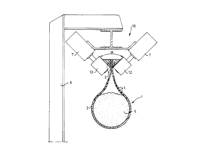
In Fig. 1 the hose belt conveyor is indicated by 1. It
comprises a belt 2 which is folded to the form of a hose. Belt 2 is
provided with thickened parts 3 at the ends, as can be seen more clearly
from Figs. 1 and 6. These thickened parts are both a right-angled
triangle. If the flat sides of the right-angled thickened parts 3 are
placed against each other as shown in Fig. 1, a V is produced. The angle
a of the V according to the invention preferably lies between 30 and
90°,
more particularly between 35 and 70°, and in a preferred embodiment
lies
between 50 and 60°. This means that the bottom angle of the thickened
parts V lies between 15-45°, 17.5-35° and 25-30°,
respectively. It has
WO 95/11848 217 518 9 - PCT/NL93/00214
~.. 5
been found that with such an angle, the opposite straight sides of the
right-angled triangles 3 have such grip that mutual displacement does not
occur. These sides are pressed against each other through the weight of
the hanging tubular part and the presence of the rollers 11 and 12 of the
drive unit, which is indicated in its entirety by 10. It is not necessary
here to provide means in these straight sides for preventing mutual
displacement, such as dovetail constructions and other special measures.
It has been found that the V-shape used here permits a rise of the belt
up to 45' in the vertical plane without slippage occurring. It is
therefore possible, when the belt is moving in the closed state through
bends, for the faces of the two straight sides of the triangular
thickened parts where they go against each other to be tilted slightly
relative to the horizontal in that position.
The contents of the hose belt 2 are indicated by 5. The drive
unit 10 already mentioned above is fitted on a frame 6. Bending belt 2 to
a hose means that the width of the hose belt conveyor during conveyance
of the same quantity of material can be considerably smaller than that in
the case of flat conveyors according to the prior art. The rollers 11 and
12 are both connected to a drive motor 7. A freewheel construction is
present between drive motor '7 and the rollers in question, so that should
one of the motors break down or irregularities occur in the running
speed, there is no unnecessary load on the V. The material from which
both the belt and the thickened parts 3 are made may be any material
known in the prior art for conveyor belts, such as rubber fabrics,
reinforced or otherwise. Through the abovementioned angle, it is possible
to provide a drive of the hose belt conveyor 1 in a simple manner. In the
case of the above-mentioned angle no slippage occurs, on the one hand,
because grip like a V-belt in a pulley is achieved. On the other hand,
the chosen angle means that the wedge force caused by the hose with
contents is not so great that the thickened parts are damaged by the
rollers or move between them or inadmissibly jam.
Figs. 2 and 3 show guide stations. In Fig. 2 the guide station
consists of a frame which corresponds to the frame shown in Fig. 1 and is
also indicated by 6. Fixed to it are non-driven rollers 8 and 9 which are
supported on pin 1'7 by means of bearings 13. Fig. 3 shows an embodiment
in which a slide support 14 is provided for bearing the thickened parts 3
of the belt. Said support is firstly provided with a smooth surface layer
15 made of, for example, Teflon material, and provided with openings 16
which are connected by way of line 18 to a source of compressed air. This
day 19. ~8~5 .
2175189
6
will cause the thickened parts 3 to float above slide support 14 during
operation.
With the aid of the above-described drive and guide devices, it
is possible to construct a complete track for the hose belt conveyor 1,
as shown in Fig. 4. In this figure the drive units are indicated by 10
and the guide devices by 20. It can be seen clearly from this figure that
both the conveying part and the return part of the hose belt conveyor lie
in the same plane, and that the return part is realised by taking angles
in the horizontal plane. It can also be seen that more than one drive
unit 10 is present. In this way it is possible to design the belt in such
a way that it can extend over very great lengths. Due to the fact that
the drive forces are applied at various points, the length of the hose
belt conveyor is in fact unlimited. In Fig. 4 supply stations for
material are indicated by 19. These may comprise any device known in the
prior art. A discharge station is indicated by 21. It is shown in more
detail in Fig. 5. As can be seen from this figure, it consists of a worm
conveyor 22, consisting of a tube 23 in which a worm 24 driven by a motor
is situated. This tube projects through a guide 26 for moving
thickened parts 3 of the hose belt conveyor slightly away from each
20 other. It goes without saying that it is possible to achieve such an
opening with other guide means. Due to the fact that the belt moves
further in the same horizontal plane after material is removed, it is not
necessary for all the material to be removed from it. For, the remaining
material can be removed in a subsequent passage through, and this
25 remaining material will. not be exposed to the environment on the way to
the next passage through, because the hose belt conveyor will remain
closed.
Finally, Fig. 4 shows a construction in which, as in the case
of conventional devices, the pocket conveyor is in fact provided with a
return part which lies in a different vertical plane from that of the
conveyor belt. For this purpose, the belt is folded open and supported
near the delivery end on rollers 27, 28, 29. The belt can be conveyed
back over a roller with relatively small diameter. This is because little
or no longitudinal reinforcements are present in the belt. For, the belt
is driven at different places so that the driving force extends over a
relatively short length. With the construction shown in Fig. 6, a self-
centring operation is obtained by means of rollers 27 and 29 interacting
with the thickened parts 3. The way in which the return part is guided
supported on rollers 35 is shown in the lower part of Fig. 6. In the case
/~'~ E'N DE's S H ~,cT
WO 95/11848 217 518 9 PCT/NL93/00214
7
of this embodiment it is possible to provide the hose belt conveyor with
a head drive having a roller in the usual way.
Although the invention is described above with reference to a
preferred embodiment, it will be clear to those skilled in the art that
many modifications may be made to it. For example, combinations with
return movement in the same horizontal and vertical plane are possible.
These and similar modifications are all considered to lie
within the scope of the appended claims.