Note: Descriptions are shown in the official language in which they were submitted.
2 17526~
139P2CA
The present invention relates to fluidized particle production systems and processes for producing
fluidized particles and is useful in particular, but not exclusively, for the production of fluidized ice
particles for ice blasting.
5 Several systems have been devised to carry out one or more functions of ice formation and removal,
and ice particle formation and transport. The removal or harvesting of ice from ice forming surfaces
of ice making units has been carried out by various methods, including melting, the use of gravity,
scrapers, or other mechanical means and a combination of the above, some of which are described
in United States Patents Nos.2,344,922; 2,995,017; 4,389,820; 4,707,951 and 4,965,968. Ice particle
formation has been carried out by scraping or harvesting (United States Patent No. 2,344,922) or
other methods involving grinding or crushing. Induction, gravity and mechanical feed technologies
have been used to facilitate ice particle transport in United States Patents Nos. 4,707,951; 4,389,820;
2995,017; 2,344,922; 4,965,968 and 2,724,949.
Batch atmospheric or "pressure pot" systems are known and used for relatively non-degradable
15 media wherein a pre-manufactured medium is loaded in batches into a holding vessel for subsequent
treatment such as sizing of particles, agitation and dispensing for transport. Such systems may be
simplified and improved in terms of capital and operational costs and complexity by continuous or
semi-continuous systems.
There are inherent problems in existing partially sealed continuous systems, especially those used
20 for particle transport and blast treatment. These systems use a purge medium of air or other gas, e.g.
carbon dioxide, in order to prevent humidity and heat intrusion, and to minimi7~ icing,
agglomeration and fluidization difficulties. It is also desirable to be able to quickly stop and start
the systems between continuous running.
2175269
- 2 -
Such purging, with the associated capital, production and operational costs, is one of the most costly
items in the system. Without total effective sealing, its practical use is wasteful. Costs may be
reduced by minimi7ing the volume required, and by maximi7ing its usage.
Prior art systems attempt to isolate particle production from treatment which comprises conditioning,
5 including sizing, cooling and drying, and also from transport of the particles. This requires costly
and complicated equipment and delicate balance of control between process unit operations.
The present invention may be most immediately employed in systems which use nozzles employing
inductive suction for transport and/or blast effect. In such systems, purge medium flow for effecting
fluidized transport of the particles is one of the most important factors in an inductive type nozzle
10 for transport and blast treatment effect. Therefore, the control and amount of the purge medium is
not only necessary for correct efficient particle m~king, treatment and transport, but also for correct
operation of the inductive nozzle for transport and the operation of a final nozzle for blast effect.
Prior art continuous systems comparable to the present invention are usually operated under partially
or wholly unsealed ambient pressure conditions and as a result suffer from inefficiency and high
15 equipment and skilled operator labour costs, which are caused by agglomeration and plugging
arising from humidity intrusion and system pressure imbalance, which requires delicate adjustment
to correct system pressure and flow imbalance. In practice, high power and labour intensive
mechanical equipment such as sealing arrangements, airlocks, vibrators, pumps and alpha radiation
have been used in an attempt to correct these deficiencies but, as with efforts to seal part of the
20 system in order to increase system efficiency, have only created further complexity and cost.
Consequently, there is a need for a simplified system that can reduce mechanical, capital and
operational costs while preserving the integrity of the solids by means of integrating isolated particle
production, sizing and fluidizing.
~ 7~9
- 3 -
Prior art systems employing positive pressure have been limited to partially sealed or individually
sealed sub-systems or batch operation, agitation, prevention of clogging or short distance fluidization
as typified in United States Patents Nos. 4,048,757 and 5,071,289.
According to the present invention, a fluidized particle production system has a solidifying unit with
5 a solidifying surface for supporting a solidified layer of a solidifiable medium and a treatment
apparatus for removing the solidified medium from the solidifying surface and sizing the removed
solidified medium into particles of desired dimensions. The treatment apparatus comprising a sizing
device co-operating with the solidifying surface for effecting therebetween the sizing of the particles.
Adjacent portions of the solidifying surface and the sizing device are displaced together with one
l 0 another so that the particles are formed without grinding the solidified medium. A housing, which
is preferably sealed, encloses the solidifying unit and the treatment apparatus and has an outlet duct
communicating with the interior of the housing, and at least one sweep fluid outlet is positioned to
discharge a flow of sweep fluid into the housing, preferably in the vicinity of the sizing device, for
fluidizing the particles and transporting the fluidized particles through the outlet duct. A sweep fluid
15 supply source is connected to the outlet and a valve between the source and the outlet controls the
pressure and flow of the fluid at the outlet.
The present invention may be employed to create particles made from solidifiable media, such as
water, additives (solid or liquid), organic solvents, plastics and any other materials that can be
solidified into a handleable friable form. Once produced, the particles may be suitably cooled or
20 further cooled and fluidized in the sweep fluid, which may be either a gaseous or liquid media, to
produce a free-flowing finished particle of a desired size suitable for either ambient or elevated
pressure transport and also surface blasting. The present invention is useful for operation together
with transportation ducts, boosting accelerators (in the case of long distance or pneumatic transport
pressure resistance), and discharge blastheads (in the case of blast cleaning and treatment).
-
- 4 - ~ ~ 7 ~
The system according to the present invention is useful for enhancing blast performance in blast
cleaning systems that use inductive type nozzles which are limited in inductive vacuum for particle
transport and are sensitive to imbalance, either in stopping or starting, or in continuous operation.
and also preferably in discharge blastheads employing such effective nozzles.
5 The solidifying unit is capable of producing friable solids and, in the case of particulate ice, may take
the form of a conventional ice-making unit. With regard to other friable solids, the invention may
be used with other known apparatus which create solidified particles, e.g. moving belt surfaces,
spray and flash dryers and preening columns.
In respect of particulate ice, and with the appropriate adjustments, the treatment unit may work in
10 conjunction with several types of conventional ice making units, including horizontal drum, vertical
drum and disc-style ice-making units. In a horizontal drum ice-making unit, there is a fixed or
variable speed rotating drum having a solidifying or forming surface on which water is frozen. The
water may be applied onto the drum by spraying or flooded wiers, or the drum may be partially
immersed in the water. Preferably, with the horizontal drum configuration, the water is first applied
lS at some distance, in the direction of the rotation of the drum, from the point where the ice is
harvested. This allows adequate pre-cooling of the drum surface and a suitable period for efficient
freezing of the water. As the drum is rotated, the water forms a solidified layer of ice. Additional
water may be applied later in the rotation cycle to increase the ice layer thickness. However, a zone
before the treatment apparatus is preferably reserved for post-cooling after solidification to enhance
.. ,
2 1 75269
the friability and handleability of the ice. The circumferential lengths of these zones depend upon
the conditions required to make a suitably friable ice. For the case of water ice used for blast
cleaning, the post-cooling zone facilitates the production of hard clear friable ice rather than normal
"wet" ice, and best use of the sweep fluid. Similarly, for other singular or combined solidifiable
5 media, to obtain hardness and friability by cooling, evaporation or curing, the same requirements
apply.
Alternatively, prior art apparatus comprising a vertical drum ice-making unit or one of more rotating
discs (not shown) can be used, the water being applied to the outer surface of a motor-driven drum,
to disc surfaces or to the inner surface of a fixed drum, as the case may be. While the use of the
10 horizontal drum is preferred, because of its geometric arrangement and space saving features, it will
be apparent to those skilled in the art that any type of ice-making or solidifying unit may be
employed in the present invention.
In the case, particularly, of the horizontal rotating drum, or the disk style ice making unit, application
of the water may be affected by partial immersion of the solidifying or forming surface(s). However,
15 for purposes of stopping and starting it is preferred that the water be applied by means of spray
manifolds or wiers. These have the advantage of more practical control of both the thickness and the
hardness of the ice layers by positioning and applying the ice at one or more application points. Such
application also simplifies that control and facilitates conditions for start up, particularly where off-
line or idle system conditions are required for practical operation.
20 In a preferred method, for simplicity and flexibility in stopping and starting the process, the dryness
and coldness of a sealed system incorporating the present apparatus may be preserved by not holding
the solidifiable medium in an immersion sump, by m~int~ining a low operational temperature and
by controlling the application of the material to be solidified. Heat tracing of distribution lines and,
if necessary, a return sump may be easily effected by means known in the art for either ambient or
25 pressure conditions.
2 1 ~5269
The treatment unit is located close to the solidifying unit, both of which are contained within the
sealed housing. If pressurized, the housing may be of a common pressure vessel design and may
allow for practical access and over-pressure protection. Gaskets and seals may be installed to prevent
pressurization loss and also air and moisture leakage into the housing. The housing is effectively
S sealed to encourage a high production rate of ice having a high quality of clarity, hardness and
friability and to allow for an eff1cient use of sweep air. High quality cold dry air may be used as the
sweep air and under pressurized conditions may be used to augment the performance of a boosting
accelerator or a discharge blasthead.
10 The treatment unit preferably comprises a harvester, a sizer, and sweep medium distribution
manifold. The sizer is positioned after the harvester in the direction of movement of the solidifying
surface. The profile of the surface of the sizer may comprise a plurality of patterned and regularly
spaced teeth designed to produce particles of a desired uniform size. and may also include a profile
suitable for harvesting the ice, in which case the harvester may be omitted. Fluidized dislodging by
15 the sweep fluid assists in both keeping the sizer clear, and also for transport of the particles. The
fluidizing media may be the same as the sweep media as a gas for pneumatic operation or a liquid
such as a liquified gas or a combination of both. Either or both media may also be used to control
the transport flow and pressurization of the enclosure for improved performance in transport and
blast effect as described above, particularly when used with an effective type nozzle.
20 The harvester can take the form of a fixed blade, which may be toothed, a rotating roller, which may
be of helical form to fracture or scrape the solidified medium from the solidifying surface. The
harvester may either be articulating or freely rotating or indexed to the solidifying surface, but in any
case will be positioned to contact the solidified medium and not the solidifying surface. The chief
function of the harvester is to fracture the solidified layer into large chunks or flakes for subsequent
25 sizing.
The sizer may take the form of a roller sizer having a profiled surface that fractures and releases
friable material away from the solidifying surface.
2 1 75269
- 7 -
For simplicity and better effect in transporting it has been found that the sizing device may be a
sizing roller positioned next to the moving solidifying surface of the solidifying unit so that a double
roller-like assembly is created. In this case, the sizing roller is profiled with spaced teeth or
5 alternatively has a helical or other profile or a combination of forms similar to that of a conventional
harvester. The roller may driven by gears, a chain and sprocket or other common means, or actll~te~l
by the rotation of the solidifying surface so that its rotation is indexed with the solidifying surface
The orientation and position of the sizing roller will depend on the type of solidifying unit used.
However, the sizing roller will be placed with a small clearance from the solidifying surface and
10 positioned so that it comes into contact with and penetrates the entire width of the solidified layer
so as to fracture and release the solidified layer.
The invention will be ~palelll from the following description of embodiments thereof with reference
to the accompanying drawings, in which:
FIGURE 1 shows a partially-broken away view in perspective of a sealed housing
containing a solidifying unit, a treatment apparatus and associated components,
according to a first embodiment of the present invention;
FIGURE 2 shows a view taken in transverse cross-section through the apparatus ofFigure 1;
FIGURE 3 shows a block diagram of an ice particle production and blasting systemincorporating the apparatus of Figures 1 and 2;
FIGURE 4 shows a broken-away view in transverse cross-section through parts of
a modification of the apparatus of Figures 1 and 2; and
2~752~9
FIGURE S shows a broken-away view in perspective of parts of the apparatus of
Figure 4.
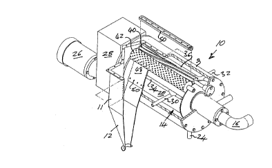
As shown in Figure 1, a sealed housing indicated generally by reference numeral 10 has a cylindrical
portion 9 and or lateral extension 11 which communicates with a downwardly convergent outlet duct
5 12. The housing 10 contains a solidification unit in the form of a horizontal ice- making drum
indicated generally by reference nurneral 14, the interior of which communicates through a duct 16
with a refrigeration unit 18 (Figure 3) for cooling a solidification or forming surface 20 on the
exterior of the drum 14.
As shown in Figure 2, the housing 10 is provided at its bottom with a drainage opening 22, which
is connected by a drain pipe 24 to a water reservoir 62 (Figure 3) for recycling water from the drum
14. An electric motor 26 is connected through a reduction gearing 28 to the drum 14 for rotating the
drum 14 about its horizontal axis.
Water supply pipes 30 and 32 are connected to perforated spray pipes 34 and 36 which extend
parallel to the drum 14 and which serve to spray water onto the surface 20 so as to build up a layer
15 (not shown) of ice on the surface of the drum 14 as the drum 14 is rotated in the direction of arrow
A of Figure 2.
The lateral extension 11 of the housing 10 has an upwardly open top which is closed in an air-tight
manner by a cover 38 which is bolted to the housing 10 and the crossing 10 and which can readily
be removed to provide convenient access to the interior of the housing 10.
20 Within the housing 10, a first roller in the form of a helical harvester roller 40 is spaced from the
drum surface 20 by a gap 41 which, effectively, forms a nip between the harvester roller 40 and the
drum surface 20.
217526~
g
The harvester roller 40 is followed, in the direction of rotation of the drum 14, by a sizer roller 42,
which likewise extends parallel to the drum 20 and which is formed on its exterior, in known
manner, with a plurality of spaced projections 44, which are spaced and dimensioned to produce, in
co-operation with the drum surface 20, ice particles of desired dimensions.
Beyond the sizer roller 42 in the direction of rotation of the drum 14, a doctor blade 48, which is
secured by screws 50 to the housing extension 9, extends in close proximity to the drum surface 20
at a location almost immediately following the sizer roller 42.
A first air outlet in the form of an air discharge manifold 50 extends parallel to the rollers 40 and 42
and is located close to the rollers 40 and 42 for directing a discharge of sweep air at the roller 42 and
between the rollers 40 and 42, as indicated by arrow B, to the outlet duct 12.
A second air outlet in the form of an air discharge manifold 52 extends parallel to the manifold 50
and is provided directly above the outlet duct 12 for directing a flow of air in the direction of arrow
C towards the outlet duct 12.
The spray pipe 34 is disposed closely below the doctor blade 48 for discharging water onto the drum
surface 20. Major solidification of this water to form a frozen layer of ice (not shown) on the drum
surface 20 then takes place in a zone defined by an arc A1 extending from the pipe 34 to the pipe 36.
It is to be understood that, while water is solidified by freezing in the present embodiment of the
invention, different media may be solidified by other means, such as curing or evaporation. Further
water is sprayed by the pipe 36 onto the drum surface 20, and final solidification of the ice layer then
takes place over a zone defined by a second arc A2 frorn the pipe 36 to the gap 41.
At the gap 41, the harvester roller 40, in cooperation with the drum surface 20, fractures the ice layer
into ice flakes.
217526q
- 10-
These ice flakes are crushed between the sizer roller 42 and the drum surface 20 so as to form ice
particles of the desired shape. The sizer roller 42 and the drum 14 therefore act as a counter-rotating
roller pair forming therebetween a nip at which the ice particles are formed. More particularly, the
sizer roller 42 is rotated by the motor 26 and the speed reduction gearing in timed relation to the
5 rotation of the drum 14 so that adjacent portions of the periphery of the sizing roller 42 and of the
drum surface are moved together with one another, i.e. in the same direction and at the same speed.
In this way, the ice flakes are crushed but not ground between these adjacent portions, thus
counteracting the formation of ice particles which are too small. These ice particles are then swept
past the sizing roller 42 by the air flow from the air discharge manifold 50 over the doctor blade 48
10 and into the outlet duct 12.
Over a zone defined by an arc A3 extending from the gap 41 to the pipe 34, the ice layer is thus
removed from the drum surface 20 and the drum surface is prepared by the doctor 48 to receive a
new layer of ice. Excess water discharged from the pipes 34 and 36 and not formed into ice particles
is collected by the housing 14 and passes through the drain 22 and the drain pipe 24.
15 The harvester roller 40 may be indexed to the drum 14 for rotation in timed relationship therewith,
in the directions indicated by arrows D, by the reduction gearing 28, but may alternatively be freely
rotatable.
The air discharge manifold 52 may be omitted in cases where it is found that the air discharged by
the manifold 50 is sufficient to effect the fluidizing and transport of the ice particles from the gap
20 46.
However, the manifold 52 or other transport and fluidizing inputs (not shown) may also be used to
provide fluid flow for desired pressuring action of the housing 10 through the control valves 74, 75,
76 (Figure 3) in order to improve the transport and blast effect.
Q
The height of the projections 44 of the sizing roller 42 is proportional to the thickness of the ice layer
on the drum surface 20, which for the purposes of ice blast cleaning is preferably in the range of
1/16" to 3/16". The spacing between the projections 44 should be in the same range and the sizer
roller 42 is preferably located so that the tips of the projections 44 are at least 1/32 of an inch from
5 the drum surface 20. This arrangement is suitable for fracturing the ice layer formed on the drum
surface 20 and then lifting the resulting particles away from the drum surface 20 with minimum
amounts of "snow" generated by pulverizing the ice. Any fractured chunks or flakes of ice which
are not released from the drum surface 20 in this way are removed by the doctor blade 48, which
comprises a non-abrasive scraper such as an aquaphobic plastic knife.
10 To avoid the production of "snow", further reduction of particle size, if required for better effect in
blast cleaning, may be effected after transport of the particles from the outlet duct 12.
In any event, the profiles of the harvesting and sizing rollers are designed to produce high quality
cold dry particles suitable for fluidized storage, transport and subsequent sizing if required for
improved blast cleaning effect.
15 The harvester roller 40 may be omitted. When the harvester roller 40 is provided, it has the
advantage that it contacts the ice and releases the ice from the drum surface 20. However, the
harvester roller 40 has the disadvantage that it produces large, randomly shaped ice flakes which
must be re-broken to the desired particle size and which must be matched to the capacity of the sizer
roller 42 without the production of too fine ice particles, which could result in plugging of the
20 apparatus.
When the harvester roller 40 is omitted, the periphery of the sizer roller 42 may be designed with
a suitable profile to produce the desired particle size by fracturing and sizing the ice in one step, thus
combining sizing and harvesting.
2 17~;26~
- 12-
Generally speaking, the smaller the particles formed or sized, the greater the diff1culty in preventing
fines built-up. A profiled harvester / sizer will normally remain clear of particles provided that they
are non-adhering e.g. in the case of water ice, dry and cold will be defined by brittle fracture upon
removal from the forming surface, and the treatment surfaces will best be aquaphobic. If required,
5 the profiled sizer / harvester may be in addition mechanically cleaned by means such as a stiff brush
using, e.g. in the case of water ice, aquaphobic bristles such as nylon or the like, e.g. as described
in greater detail below with reference to Figures 4 and 5 or by a serrated fixed blade suitably fixed
in proximity to the sizer and harvester rollers. Fixed blades operating on a forming surface have
worked and are known in the art, but produce "shaved" fines and do not produce discrete sized
10 particles and therefore have no useful value for blasting and cause agglomeration, build-up and
transport problems. For purposes of particle production, fixed blades are better used to scavenge
those ice portions not previously removed.
The present apparatus uses internal stresses in the ice layer to fracture uniform sizes rather than
scraping, grin(ling or milling. The fracturing should be effected with minimllm relative velocity, and
15 by pressure applied by profiled shapes so that the natural brittleness and the expansion or contraction
of the material will free it from both the drum surface, and also the harvester and sizer rollers.
Fracture and sizing should be via directed forces in a pattern to produce desirable particle sizes,
using the internal stresses of the solidified ice, rather than high power from the sizing roller.
Consequently, prior art double profiled rollers and impact mills are less effective than the present
20 apparatus.
The initial function of the sweep air from the manifold 50 is to dislodge the large ice chunks or
flakes and sized particles from the drum surface 20, harvester and sizer rollers 40 and 42 and the
walls of the housing 10. It is preferable that the sweep air be pressurized. In addition to the
advantages of over pressuring the ice-making unit for hurnidity control, the pressurization improves
25 the quality and density of the ice formed in the ice-making unit by minimi7in~; the formation of air
bubbles within the ice, and aids in the sealing of the system (by excluding any leakages). In addition,
pressurization provides a driving force for sweeping and fluidizing the ice particles, for transport to
~1 7~fi~
- 13 -
the outlet duct 12 and for overcoming longer transport duct resistance to the booster accelerator or
discharge blasthead, if included. Pressurization also improves accelerator booster and discharge
blasthead performance, where final discharge is controlled by a constriction such that transport
velocities within the transportation duct are kept low to prevent particle degradation. In the case of
5 eductor type nozles which rely on low suction pressures, pressurization can create a large positive
pressure gradient, thereby increasing the driving force behind the particulate flow.
It is important to note that pressurization of the solidifying system and transport does not imply
velocity in the transport duct or hose. Velocity and associated attrition and heat build up may be
controlled through mechanical, or more simply, pneumatic restrictions generated by transport
l O boosters or blast heads.
The sweep air pressure within the sealed housing 10 with correct sweep air control may have a
pressure as low as 0 psig, which is adequate for pre-cooling of the entire system and transport duct,
and cooling of the particles and will allow for a cost-effective low pressure vessel housing design.
However, pressures equal to or greater than 50 psig should be used for an optimal blast cleaning
15 effect. The sweep air should have a low humidity and temperature so as to m~int:~in the hardness and
dryness of the ice particles formed. In the case of where the ice formed requires further cooling, the
humidity and temperature should be m:~int~ined to facilitate friability. The high cost of cool and dry
sweep air may be reduced by using lower quality accelerating air at the booster accelerator and
discharge blasthead. In addition, somewhat higher humidity and temperature sweep media may be
20 used to reduce overall power consumption of the system if the ice is produced at low temperatures
of -10~C or lower. For ice production at these temperatures, the sweep air need only be dehumidified
to the pressure dew-point temperature of the water in order to reach acceptable conditions of
friability, cooling, fluidization and transportation. Gases other than air normally do not require
dehumidifying. Dehumidification of air may take place by treating compressed sweep air (100-150
25 psig) with filters and traps for the removal of particulates and oil, and normal air/air or air/water
after-coolers for initial dehumidification. Final drying, if required, may be completed in two steps.
A
2 ~ 75269
- 14-
First, the sweep air will be cooled to just above the freezing point of water and dried by a refrigerated
heat exchanger, which will remove virtually all of the water content. All the above-described
treatment equipment is known in the art. Alternatively, desiccant dryers or vortex tubes may be
used. A final heat exchanger will cool the air to -18 to -12~C. Upon release of this pressurized
5 dehumidified air within the sealed housing, the air will expand and reach even lower temperatures
compatible with ice formation, further cooling of the ice particles and counteracting heat intrusion
into the entire system and during transport.
The pressure, temperature and humidity ranges described above provide smoothness of flow and
prevent agglomeration and plugging. Variation of the positive pressure gradient between the
10 solidifying unit and booster accelerator or discharge blasthead may be carried out by modulation of
the sweep air input into the sealed housing and its resulting pressure or by an adjustable fluidized
pneumatic restriction located at juncture of the treatment unit and transportation duct, the modulation
of an effective nozzle, or a combination of all.
In the case of blast treatment, flow of the ice particles may be precisely controlled and optimized
15 mechanically or pneumatically with the effective type nozzle. The ice making rate can be varied by
modifying the speed of the forming surface 20, the supply and temperature of the refrigerant or the
rate of supply of water to the drum surface 20. Alternatively or conjunctively, the relative
downstream pressure in the transportation duct may be varied, as described, against the effect of the
sweep air pressure or the pneumatic restriction, or the booster or accelerator, thereby further
20 expanding the range of operational flow rates possible.
Referring now to Figure 3, which shows a block diagram of a blast cleaning system incorporating
a fluidized particle production system according to the present invention, indicated generally by
reference numeral 60, illustrates diagrammatically the fluidized particle production system shown
in Figures 1 and 2.
- 15 - ~ ~ 7 ~ ~ ~ 9
The ice making drum 14 is shown in Figure 3 as being cormected to the refrigeration unit 18 by pipes
24 and 25. The spray pipes 34 and 36 are connected to a water reservoir 62 by a pipe 63 for
supplying water from the water reservoir 62 to the drum 14 and the drain pipe 16 returns excess
water from the drum 14, through a liquid-only flow limiter similar to a steam condensate trap 64,
5 to the water reservoir 62.
A compressed air source 66 is connected through an air dryer and cooler 68 and through a manually
or automatic ON/OFF valve 70 to the particle production system 60. More particularly, the valve
70 is connected through a line 72 to the air discharge manifold 50, and through a two-way
RUN/IDLE valve 74, a RUN valve 75 and an IDLE valve 76 to the manifold 52. By manual
10 adjustment of the valve 74, the compressed air from the compressed air source 66 can be supplied
through the valve 75 while the system is in operation for producing particles, and through the valve
76 while the system is idling. The valves 75 and 76 are manually adjustable to pre-set and then
automatically control the pressure and flow supplied to the air outlet manifold 52, and therefore the
resulting pressure in the housing 10.
15 The air dryer and cooler 68 is also connected through an ON/OFF valve 78 and an adjustable
pressure control valve 79 to an accelerator 80.
The purpose of the accelerator 80 is to accelerate the fluidized stream of particles supplied from the
outlet duct 12 through a transport hose 82 to a blasthead 84, from which the particles are discharged
through an outlet nozzle 86 for impact against a target surface 88.
20 The purpose of the dryer/cooler 68 has been described. In some cases, the dryer/cooler 68 may be
omitted, and process air may then be supplied via another source 94.
A
2 1 75269
- 16-
Also, in cases where transport through the hose 82 is adequate, particularly where the housing is
pressurized, the accelerator 80 and its motive fluid supply from dryer/cooler 68 may not be required.
Compressed air from the compressed air source 66 is supplied to the blasthead 84 through an
ON/OFF valve 90 and a pressure control valve 92. An alternative compressed air or other fluid
5 source 94 may, if desired,. be employed to supply to or replace the air dryer and cooler 68. The
particle production system 60 is provided with an overpressure safety relief valve 96 for venting the
housing 10 to the atmosphere in case an excess pressure occurs within the housing 10.
Figures 4 and 5 show a modification of the apparatus illustrated in Figures 1 and 2. As shown in
Figures 4 and 5, a brush indicated generally by reference numeral 100 is mounted in proximity to
the outer surface of the sizer roller 42, with the bristles of the brush 100 brushing against the roller
surface for removing any pieces of ice rem~ining on the parts of the surface of the roller 42 which
have rotated beyond the location at which the ice particles are formed. The brush 100 is secured by
nuts 104 and bolts 106 to a support plate 108. As can be seen from Figures 4 and 5, the brush 100
is provided with an elongate slot 112 through which the bolt 106 extends, so that the brush 100 can
be adjusted in position relative to the sizer roller 42 and then secured by tightf ning of the nut 104.
The brush 102 is likewise adjustable in position relative to the sizer roller 42.
Beneath the support plate 108, there is provided an air outlet manifold 114 in the form of a
perforated pipe having outlet openings 116 directed towards the sizer roller 42.
Any ice still rem~ining on the surface of the sizer roller 40 after the sizing of the ice between the
20 sizer roller 42 and the drum 14 may then be dislodged by the air discharged from the air outlet
manifold 114 and by the brush 100, and is then guided by the support plate 110 towards the outlet
duct 12.
Alternatively, the brush 100 may be replaced by a brush 102 mounted on a support plate 110, which
are shown in broken lines in Figures 4 and 5.
217~269
- 17-
Beneath the support plate 110, there are provided two air outlet manifolds 118 and 120. The air
outlet manifold 118 has outlet openings 122 directed towards the sizer roller 42, whereas the air
outlet manifold 120 has outlet openings 124 directed towards the outlet duct 12. The ice particles,
and also ice rem~ining on the portion of the surface of the sizer roller 42 which is moving beyond
5 the drum surface 14, are fluidized by air blasts from the outlet openings 122 of the air outlet
manifold 118. The air from the air manifold 120 then assists the movement of these particles
towards the outlet of duct 12.
As can be seen from Figure 4, a scraper blade 126 replaces the doctor 48 of Figure 2, and serves to
guide the ice particles towards the outlet duct 12.
The brushes 100 and 102 may, if desired, be replaced by suitable profiled scraper plates of
aquaphobic material. Likewise, the scraper 126 is preferably formed of a slick, aquaphobic material
to counteract the deposition of the ice particles on the scraper 126.
It will be understood from the foregoing description and apparent that various modifications and
alterations may be made in the form, construction and arrangement of the parts thereof without
15 departing from the spirit and scope of the invention as defined by the appended claims, the forms
herein described being merely preferred embodiments thereof.