Note: Descriptions are shown in the official language in which they were submitted.
t 2175404
-1-
EXTERNAL BONE FIXATOR
FIELD OF THE INVENTION
This invention relates to a bone fixator. In
particular it relates to an external bone fixator for
use in the treatment of fractured bones such as the
tibia and a method of monitoring the use of such a bone
fixator.
BACKGROUND OF THE INVENTION
Bone is adept at self-healing, with new bone
(callus) formation at the fracture site being able to
reunite the fragments of the fractured bone. Medic_al
treatment of fractured bone aims to assist and promote
this natural healing.
One method of treatment involves the use of
internal fixation whereby an.implant (e.g. a bone
plate) is directly attached to the bone fragments to
rigidly hold them in place whilst healing takes place.
Such treatment results in excellent alignment of the
bone fragments. Such treatment does not allow relative
motion between the two rigidly held bone fragments.
Biological research has shown that certain types of
callus formation is only triggered and maintained by
relative motion of the bone fragments. Rigid fixation
of the bone fragments therefore leads to a reduction in
the formation of certain types of callus and therefore
delays natural healing. Other types of medical
treatment such as external supports (e.g. plaster of
Paris casts), although allowing relative movement of
the bone fragments and thereby promoting good callus
formation, are not able to assist in precise and
accurate bone fragment realignment. Attempts have
therefore been made to develop devices for the
treatment of bone fractures which hold the fragments
sufficiently rigidly together to allow accurate
realignment and yet at the same time_ allow sufficient
relative movement between the bone fragments to promote
2175404
~ -2-
and not inhibit callus formation.
DESCRIPTION OF PRIOR ART
One such attempt is the Orthofix external fixator,
e.g. as described in EP-A-0011258. This device is
applied externally to the injured limb and is attached
to the bone fragments by bone pins or screws passing
through the soft tissue of the limb into the bone.
Bridging the gap between the pins in the two separate
fragments is a rigid support bar, which holds the
fragments in alignment. When the support bar is formed
by telescopic elements the distance between the pin or
set of pins attached to one of the bone fragments to
the pin or set of pins attached to the other bone
fragment can be varied. Such distance variation allows
in theory for forced axial movement of the bone
fragments relative to each other. This device suffers
from the disadvantage that it is doubtful whether true
axial movement occurs when it is applied to a tibia
fracture. Once the fixator is unlocked axially, the
fractured ends compress. There is then no force which
would tend to pull the fractured ends apart again
during normal movement. For this to occur; a strong
spring would have to be introduced to hold the -
fractured ends apart so that they could be driven
together by weight bearing. The fracture would then,
however, be distracted, i.e. forced open, in the
resting phase. Pneumatic, electromagnetic or
electrical systems to overcome these problems would be
expensive and cumbersome. It has also been found that
relative axial motion promotes a long thin callus
configuration which does not help to prevent the most
common type of refracture.
In EP-A-0458486 a device is described which -
attempts to act as an external fixator which allows
hinged movement about two separate planes. Although it
is not clear how t-Ais device would work in practice, it
2175404
-3-
is disclosed as being constrained to move in one hinged
plane at a time. The constrained movement of the
fixator could allow the bone fragments to move about a
hinge in two planes only with respect to each other.
This would lead to an uneven callus formation only
along the lines of the hinged planes. To even out
callus formation with this device it would be necessary
for the position of the device relative to the bone
fragments to be adjusted on a regular basis which would
require repetitive visits to a medical practitioner.
- Whilst-many bone fixation systems, such as those
discussed above, have been developed and some are
presently in use clinically, there has been to date no
means of accurately obtaining continuous information
about their use in practice by patients. Obtaining
such information would be of use in the assessment of
the usefulness of current designs of bone fixation -
systems, in the development of future improved designs,
and in the assessment of the efficient treatment of
fractured bones.
SUMMARY OF THE INVENTION
There is therefore a need for an external fixator
which allows for accurate realignment of bohe fragments
and at the same time allows movement around the
fracture site to generate an even peripheral callus and
this is an object of the present invention. Such
allowed movement must be closely controlled to provide
the desired type of relative movement only.
There is therefore a need for means by which the
use of a bone fixation system can be monitored, and
more particularly by which the use of an external bone
fixator, which allows relative movement between
fractured bones, can be monitored. -
According to a first aspect of the present
invention there is provided an external fixator for use
in the tre~atment of a fractured bone having a first
2175404
-4-
bone fragment and a second bone fragment which external
fixator comprises:
means of attachment to the first bone fragment of -
the fractured bone;
mea-ns of attachment to the second bone fragment of
the fractured bone; -
a first rigid support bar having a first end and a
second end, being connected to the first means of
attachment at its first end and extending
longitudinally therefrom;
a second rigid support bar having a first end and
a second end, being connected to the second means of
attachment by its first end and extending
longitudinally therefrom;
a first movable element attached to the second end
of the first support bar;
a second movable element attached to the second
end of the second support bar,
wherein the first movable element is movably
mounted in the fixator so as to be capable of_angular
motion in one plane, and the second movable element is
movably mounted in the fixator so as to be capable of
angular motion in another plane, with the plane_in
which the second element moves being substantially
orthogonal to the plane in which the first element
moves, and the first and second movable elements are
coupled together in such a way as to allow simultaneous
angular movement of the external fixator in the two
substantially orthogonal planes.
The first and second elements should be mounted so
that the only relative motion allowed is the angular
motion in the two substantially orthogonal_planes, i.e.
each of the first and second elements is only capable
of movement in one orthogonal plane. It is not capable
of any other type of movement. _
When a fixator according to the present invention
2175404
.~.
-5-
is attached to the bone fragments of a fractured bone,
the fragments are held in alignment and the movement
allowed corresponds to that possible in the fixator-.
(Some additional movement may be allowed via the bone
pins or screws. This can be minimised by taking
suitable measures-such as shortening and thickening the
pins or screws used.) The relative motion of the
movable elements of the support bar is translated into
controlled angular motion of the bone fragments around
the bone fracture site. The fixator allows angular
motion in any plane in which the longitudinal axis of
the fracture bone lies. The loci of the allowed
movement of one fragment to the other will be defined
by shapes approximating to a cone. Other relative
motions such as shear (translation), torsion (rotation)
and axial motion are prevented by the fixator. The
- bone fragments can freely move angularly with respect
to each other, i.e. they are free to hinge or pivot
(flexion/extension) with.respect to each other in any
direction.
The controlled angular movement allowed by the
fixator should be centred at the fracture site. The
fixator should be positioned_with respect to the bone
fragments so that the substantially orthogonal planes
are centred at the centre of the fracture site. To do
this the axis about which the angular.znotion occurs of
at least one of the coupled elements should lie
substantially parallel to the longitudinal axis of the
bone to be treated.
In order to obtain accurate remote centring of the
fixator i.e. to obtain this parallel alignment, it is
desirable to build into the fixator means of varying
its alignment-to the fractured bone. Where accurate
bone pin alignment to the fracture site is possible, by
which the fixator can-be accurately aligned to the
fractured bone, then-it is not necessary to build into
2175104
-6-
the fixator means of varying its alignment to the
fracture. Such accurate pin alignment may be carried
out by fixing the fractured parts together in their
reduced state before drilling in the pins which are to
hold the fixator. One particular method of accurately
aligning the pins is as follows. Small diameter pins
which are not required to pass right through the bone
but need only penetrate the first cortex as they are
not intended to be load bearing are applied to each of
the bone fragments. Next a reduction device is used to
accurately align the fractures, i.e. to accurately
reduce them. Once the fracture has been satisfactorily
reduced the fixation device of the present application
is attached with two sets (e.g. of three pins each) of
standard size weight bearing pins. As the bone
fragments are held in place by the reduction device the
pins can be precisely located with an alignment jig
drill guide so that they are all parallel and in line
and also perpendicular to the bone surface or -
longitudinal axis of the bone and so allow accurate
orientation of the fixator.
The degree of relative angular movement allowed to
the fractured bone fragments is dictated by-the degree
of angular freedom allowed in'the fixation device. The
upper limit of the permitted degree of movement is
determined by the pain or a sense of instability which
would be caused to or sensed by the patient by the
corresponding movement of the fragments. If too large
a degree of movement occurs unacceptable levels of pain
will be experienced. A degree of angular freedom of
plus or minus 5 for each of the first and second
elements measured from their central resting position
is presently considered suitable for the upper limit.
A preferred upper limit for the permitted range of
movement is in the order qf plus or minus 2 to 3 e.g.
plus or minus 2.5 . 7
2175404
-~-
The coupling of the first and second members may
take any suitable form.
The fixation device may be provided with a third
or coupling member to which the first and the second
members are each mounted, i.e. the first and second
members may be coupled together by a third or coupling
member. In such a case either the first or second or
both members may be pivotally mounted on the third or
coupling member.
Pivotal mounting of the movable elements may be
accomplished by mounting on a pivot pin. Alternative
pivotal mounting can be achieved by provision of an
arc-shaped cam surface on which a suitably provided
follower can be guided. The movable member can be
provided with an arc-shaped cam surface, e.g. an arc-
shaped slot or passage or housing, or with a cam
follower which follows a cam surface provided on
another component of the fixator, e.g. on the third or
coupling member. -
In a preferred embodiment the first member is
pivotally mounted on a third member by means of a pivot
pin about which it is able to pivot and the_second
- member is provided with one or more projections which
are received within one or more arc-shaped slot on the
third member.
For a compact design one of the first -0r second
movable members may take the form of an open housing
into which the other member may be received. If
present the third or coupling member may also be
received within the housing. The dimensions of the
housing may be used to limit the degree of freedom of
movement of the movable member mounted within it.
Alternatively the first and second members may each
take the form of a two-limbed member in the substantial
form of the head of a tuning fork. The two members are
then positioned ortiiogonally to each other and joined
21'75 404
-8-
by the third or coupling member.
At their non-coupled ends the first and second
member may be suitably shaped so as to function as
support rods. The support rods may instead of being
integral, however, be separate from (but connected to)
the coupled movable elements. In this latter case the
support rods and movable elements together form the
support bar.
It is desirable for the fixator to incorporate
return mechanisms to return one or both of the movable
elements of the fixator to its central position when
unloaded. This will allow accurate alignment of the
fracture when the limb is at rest. The return
mechanism could take the form of a spring, i.e. a
component which deflects under stress and returns to
its original dimensions and configurations when the
stress is removed. A return mechanism may be
associated with each of the movable elements. The
return mechanism associated with the first element may
differ from or be the same as that associated with the
second element.
The means of attachment of the support bar to the
bone fragments may take any suitable form. It is usual
for external fixation devices to be fixed to the bone
fragments by percutaneous or transcutaneous pins or
screws, i.e. pins or screws which transect the skin._
Such bone pins or screws may either be transfixion
pins, i.e. ones which pass completely through the bone
and limb and emerge on the other side, or half pins
which fasten into the bone and do not emerge therefrom.
If transfixion pins are used a fixator can be attached
on either end of the pins, i.e. a fixator can be
attached on either side of the limb (bilateral). If
half pins are used only one fixator will be attached on
only one side of the limb (unilateral).
The fixation device may be attached to the bone
2175404
-9-
fragments by any suitable number of pins, e.g. one, two
or more. It is preferred that three pins are used to
attach to each bone fragment as this number leads to
good stress reduction at the bone interface and would
allow for the removal of one pin if necessary, leaving
two for sufficient stability. If only two pins were
used and one was required to be removed, further
operation may be required for the insertion of another
pin to ensure stability. Each of the pins should be in
substantially parallel alignment with its neigghbours.
The fixator then requires means of attachment, for
example clamps, able to fixedly attach to the bone pins
or screws. Such means may be integral with or separate
from the support bar,- e.g. the coupled movable elements
or the support rods. The attachment means, e.g.
clamps, can have any suitable design but should be
adapted to allow for easy attachment of the fixator to
the bone pins or screws irrespective of their relative
positioning and alignment. For this purpose the clamps
may, for example, be provided with means to adjust
their orientation within a reasonable range of
diversion to allow connection to the bone pins attached
to each of the bone fragments. Preferably the clamps
are provided with the possibility of movement in three
planes, i.e. so that they have 6 degrees of freedom of
movement. Movement in each of these planes must be
lockable so that final alignment can be maintained.
Such adaptation could include the use of ball joints.
In use to reduce the mechanical stresses induced
on the fixator/pin connection and throughout the rest
of the fixation device, it is preferably for each means
of attachment, e.g. clamp, to be positioned as close to
the'skin of the limb being treated as possible to
- minimise the effect of bending moment.: However, since
direct contact between the external structure and the
soft tissue is medically inadvisable a minimum
2175404
-10-
clearance of at least 1 cm is recommended.
The fixator is preferably provided with a
disabling mechanism by which the controlled angular
motion may be prevented. By this mechanism the fixator
would be converted to a rigid external fixator.
The fixator device of the present application is
particularly suitable for the treatment of fractures
which have occurred to the tibia.
The fixator may be made of any suitable material,
-10 such as those used conventionally in orthopaedic and
prosthetic components. Such materials are those which
are corrosion resistant, cleanable and sterilisable.
The material is preferably X-ray transparent or
translucent to allow X-rays of the fracture to be
carried out whilst the fixator is in place. Carbon
fibre composites are suitable materials that would be
X-ray translucent. _
The material chosen for the device may be such as
to reduce its weight to a minimum, e.g.- cast aluminium
high strength alloys could be used.
The present invention is advantageous as it will
allow improved fracture healing which will benefit the
patient and also reduce demands on the Health Service.
Furthermore, the present fixator is easy to accurately
apply and requires little or no readjustment during the
healing process. Conventional fixation devices in
contrast may require second or third time adjustment of
the fixator, some times under anaesthetic, either due
to incorrect original alignment or to vary the range of
permitted motion of the fragments at the fracture site.
With the present invention subsequent adjustments are
reduced to a minimum and the device itself cannot go
out"of alignment. This will reduce the stress to the
patient of extra operations and will also relieve
valuable operating time. The patitent will benefit from
reduced healing time and improved mpbility. Patients
CA 02175404 2007-06-07
- 11 -
may be able to return to work in a shorter period. Further the
controlled angular motion within the fracture site provided with
the present invention leads to an approximately spherical or
fusiform mass of callus which is best able to resist the commonest
mode of refracture. With the fixator of the present
invention such callus formation is easily activated by the movement
of ambulation. The fixator also prevents the harmful movements
of shear and rotation and prevents shortening in a fracture which
is axially unstable.
According to a second aspect of the present invention there is
provided a bone fixation system for use in the t reat ment of a
fractured bone, which fixation system is provided with a data
logging device which is capable of sensing and storing data relating
to the frequency of occurrence of an event associated with at least
one physical characteristic of the fixation system.
According to a third aspect of the present invention, there
is provided a bone fixation system for use in the treatment
of a fractured bone, which fixation system comprises bone fixation
means for supporting a fractured bone during healing thereof, and a
data logging device carried by the fixation means and which is
operable constantly whilst the fixation means is in place to sense
and store data relating to the frequency of occurrence of a physical
event associated with at least one physical characteristic of the
fixation system.
According to a fourth aspect of the present invention there is
also provided a method of monitoring the use in the
treatment of a fractured bone of a bone fixation system, which
method comprises sensing and storing data relating to the frequency
of occurrence of an event associated with at one least one
p h y s i c a l characteristic of the fixation system using a data logging
device with which the fixation system is provided.
According to a fifth aspect of the present invention, there is
provided a method of monitoring the use in treatment of a
fractured bone of a bone fixation system comprising bone fixation
means which supports the bone during healing, which method comprises
constantly sensing and storing data relating to the frequency of
occurrence of a physical event associated with at one least
CA 02175404 2007-06-07
- lla -
one physical characteristic of the fixation system using a data
logging device carried by the fixation means.
With the present invention it is possible to accurately obtain
continuous information about the use of the fixator by the patient.
The data logging device may be separable from the fixation
system or it may be an integral part thereof. It may, for example,
be optionally removably attached to a suitable part of the fixation
system. It may be so attached externally or more preferably
internally,
2175404
-12-
e.g. within a support bar or limb of the fixation
system.
The data logging device must be capable of
recording data in a form in which it can be readily
used by a computer. In general terms in the data
logging device information about the frequency of
occurrence of the event associated with a physical
characteristic which is being sensed is fed via a
suitable transducer, which converts it into a usable
signal, to a memory where it is recorded and stored.
The data logging device may at a convenient point in
time be suitably connected to a computer for
downloading, i.e. reading of the data stored in the
memory. The data logging device may be adapted so that
it can be downloaded whilst the fixation system is
still in use by a patient (i.e. whilst it is still in
place on the limb of the patient), alternatively either
the data logger alone or the fixation system
incorporating the data logger can be removed from the
patient and downloaded in isolation.
The data logging device must be portable so as not
to hinder the free movement of the patient using the
- fixation system. It should, therefore, be independently
powered, e.g. using suitable batteries.
If it is desired to sense or record the number of
times a specific event relating to a physical
characteristic takes place within a certain time
interval the data logging device could be provided with
a clock of suitable form.
The data logging device can be adapted to sense
the occurrence of any desired characteristic or
characteristics. Examples of physical characteristics
which may be sensed are relative position, strain,
pressure, and displacement. Information regarding
displacement of the fixation system or components of
the fixation system is particularly useful as it can be
2175404
-13-
analysed to directly relate to bone callus formation
and fracture healing. Various aspects of displacement
of the fixation system and its components may be
monitored using the present invention, e.g. the type of
displacement (axial, lateral/medial,
posterior/anterior, angular etc.) and the degree or
extent of displacement. The data logger is programmed
to log the occurrence of an event when it senses a
certain predetermined limit of the physical
characteristic being sensed. If relative movement in a
given plane is being sensed the data logger may record
that an event has taken place when a certain amount of
movement in that plane has been sensed. Movements
below the predetermined limit will-be ignored. The
data logger may need to be individually calibrated for
each patient. The present invention could, for
example, be used to record the number of times a given
(predetermined) level of displacement occurred in two
- individually sensed orthogonal planes in a given time
interval, e.g. a half hour. Such recording could take
place continuously throughout the day and could provide
information as to how regularly the fixation system or
one or more of its components was displaced. Where
displacement in the fixation system is directly related
to displacement of the fractured bones such information
- could be used to investigate the amount or type of
relative movement occurring at the fracture site.
Little displacement would be expected initially whilst
the affected limb was too painful to move.
Displacement should increase as the patient began to
use the limb more but the fractured bones were still
relatively mobile. Displacement frequency should
decrease again with time as callus formation increased
and "knitt-ed" the bones back together preventing -
relative movement. Information on displacement
frequency could therefore show how healing was
2175404
-14-
progressing. This will aid the physician in charge of
the patient in determining whether initiation of the
healing processes has_taken place and when complete
healing can be expected. The logged information could
also show that an observed patient was not moving
enough to promote healing. The invention could
therefore also be used as an aid to motivate patients
to take an active role in the healing process.
The data logging device or the fixation system
could be provided with indicator means which indicated
when a certain individual event or condition, as -
measured by the data logger, had occurred. It could
also show whether given levels of frequency of event,
e.g. displacement, had occurred. This could motivate
patients to move more if certain target frequencies of
displacement were not reached as shown by the
indicator.
The present invention may be used with any
suitable bone fixation system and preferably one th&t
allows relative movement of the bone fragments. It
could for example be used with an internal fixation
system but more preferably it is used with an external
bone fixation system. Suitable external fixation
systems include external supports, such as a plaster of
paris cast or curable resin support or any type of
external bone fixator. It may, for example, be used
with an external bone fixator which allows relative
movement between the bone fragments. One such fixator
is the OrthofixT' external fixator, e.g. as described in
EP-A-0011258. In such a fixator the support bar or
mechanism is formed by telescopic elements, so that the
distance between the pin or set of pins attached to one
of the bone fragments to the pin or set of p-ins
attached to the other bone fragment can be varied.
Such distance-variation allows for forced axial\
movement of the bone fragments relative to each -Vther.
2175404
-15-
Another fixator which is particularly preferred
for use in the present invention allows relative
angular movement of the fractured bones, e.g. as
described above in relation to the first aspect of the
present invention.
The means of attachment of the fixation system to
or around the bone fragments may take any suitable form
such as that used conventionally for the type of
fixation system in question. It is usual for external
fixators to be fixed to the bone fragments by
percutaneous or transcutaneous pins or screws,- i.e.
pins or screws which transect the skin. Such bone pins
or screws may either be transfixion pins, i.e. ones
which pass completely through the bone and limb and
emerge on the other side, or half pins which fasten
into the bone and do not emerge therefrom. If
transfixion pins are used a fixator can be attached on
either end of the pins, i.e. a fixator can be attached
on either side of the limb (bilateral). If half pins
are used only one fixator will be attached on only one
side of the limb (unilateral). The fixator may be
attached to the bone fragments by any suitable number
of pins, e.g. one, two or more. It is preferred that
three pins are used to attach to each bone fragment as
this number leads to good stress reduction at the bone
interface and would allow for the removal of orie pin if
necessary, leaving two for sufficient stability. If
only two pins were used and one was required to be
removed, further operation may be required for the
insertion of another pin to ensure stability. The
fixator should have means of attachment, for example
clamps, able to fixedly attach to the bone pins or
screws. Such means may be integral with or separate
from the fixator itself.
The fixation system and its data loggitng device
may be made of any suitable material, such ab those
2175404
-16-
used conventionally in orthopaedic and prosthetic
components. Such materials are those which are
corrosion resistant, cleanable and sterilisable. The
material is preferably and where possible X-ray
transparent or translucent to allow X-rays of the
fracture to be carried out whilst the fixation system
is in place. Carbon fibre composites are suitable
materials that would be X-ray translucent.
The material chosen for the data logging device
may be such as to reduce its weight to a minimum, e.g.
cast aluminium high strength alloys could be used.
The present invention is advantageous as it will
allow the use of bone fixation systems, including those
which allow relative movement of fractured bones, to be
monitored and assessed. This will provide information
useful in the assessment of current designs of fixation
systems, in the development of future improved designs
and in the assessment of the efficient treatment of
fractured bones, e.g. to predict optimum fracture
healing time. The invention will allow monitoring of
the fracture over a period of weeks ev-en months.
BRIEF DESCRIPTION-OF THE DRAWINGS
For a-better understarnding of the present
invention and to show how the same may be put into
effect reference will now be made, by way of example,
_ to the accompanying drawings, in which:-
Figure 1 is a schematic view of an external
fixator attached to a fractured bone;
Figures 2 a) and b) are cross-sectional views of a
first embodiment of the present invention;
Figures 3 a) and b) are perspective views of the
individual components of a second embodiment;
Figure 4 is a side view of the assembled -
components of the second embodiment shown in Figure 3;
Figures 5 a) and b) are front elevational and
cross-section views of a third embodiment of the
2175404-
-17-
present invention;
Figure 6 is a schematic view of a fourth
embodiment;
Figures 7 a), b) and c) are planar, cross-
sectional and side elevational views of a fifth
embodiment; -
Figures 8a), b) and c) are front, side and end
elevational views of a sixth embodiment; and
Figure 9 is a schematic view of another external
fixator attached to a fractured bone.
DETAILED DESCRIPTION OF THE INVENTION
In Figure 1 a fractured bone 1 is shown, which has
been broken into an upper fragment 2 and a lower
fragment 3. Support is given to the fractured bone by
an external fixator 4. The fixator 4 is in the form of
rigid support bar extending substantially parallel to
the longitudinal axis of the bone (or as close to
parallel thereto as is possible). It is attached to
the upper and lower fragments 2 and 3 by two pairs of
bone pins 5a, 5b which extend in parallel to each other
and substantially perpendicularly to the longitudinal
axis of the bone 1.
In Figure 2 a first embodiment of a fixator
according to the present invention is shown. The
fixator 6 of the embodiment has two rigid support arms
or rods 7a,-7b which extend along the longitudinal axis
of the fixator 6, which in use should be substantially
parallel to the longitudinal axis of the bone. Towards
their extremities the support rods 7a, 7b are each
provided with two channels 8a, 8b perpendicularly
extending right through the support rods 7a, 7b. These
channels 8a, 8b are used for receiving bone pins or
screws, which may be clamped therein (e.g. by screws)
to fixedly attach the fixator 6 to a fractured bone in
which the pins are implanted. The support rods 7a, 7b _
are each attached at their other ends to one of the
2175404
-18-
movable elements of the fixator. The first movable
element 9 is U-shaped in side elevation and is formed
from two substantially parallel ext-ending limbs 91a,
91b rising up from a support base 92. Towards their
distal ends the limbs 91a, 91b are each provided with
an aperture. The second movable element 10 takes the
form of an open-ended chamber or housing 101. In this
embodiment it is substantially cuboid having one end
wall and two side walls but no top or other end wall.
The first movable element 9 is mounted within the
second movable element 10 and extends out of the open
end wall. The two elements 9, 10 are coupled together
by a block 11 which is accommodated within the chamber
of the second movable element 10 and acts as a third or
coupling element. The movable elements 9, 10 are both
movably attached to the block 11, which in this
embodiment is cuboid. The block 11 fits within the -
limbs 91a, 91b of the first movable element 9. The
first movable element 9 is pivotally mounted on the
block 11 by a pivot pin 12 which extends
perpendicularly to the longitudinal axis of the fixator
6 (and in use also of the bone). The first element 9
is able to pivot about pin 12 by about two and a half
degrees in either direction. It is constrained from
larger degrees of angular movement by the dimensions of
the chamber 101 of the second element 10. The second
element 10 is mounted on the block 11 by two pins 13a,
13b which extend through the block 11 substantially
orthogonal to the pivot pin 12 by which the first
element 9 is mounted. These substantially orthogonal
pins 13a, 13b are mounted in pairs of radial slots 14a,
14b a pair of which are provided on each side wall of
the second element 10. Relative to the first element 9
and the block 11, the second element 10 is able to move
about-the fixing pins 13a,-13b along an arced path
defined by the radial slots.
2175404
-19-
In use the pivot pin 12 should be aligned with the
level of the fracture and the fixator 6 clamped on to
pins fixed in the bone at a distance from the bone so
that the centre of the arc along which the second
element 10 moves is substantially at the centre of the
fracture site.
In this manner the centre of rotation of the
fracture site is projected using a remote centre
arrangement. In this way the fixator 6 is caused to
respond to a given movement in the same way that it
would do if it had been directly acted upon by the same
movement at the fracture centre.
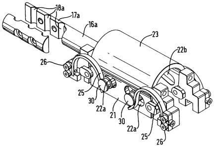
The second embodiment, i.e. that shown in Figures
3 and 4, is very similar to the first embodiment but
includes a return mechanism to return the fixator back
to its central position when unloaded to ensure that
the fracture is aligned correctly when the limb is at_
rest. The fixator 15 of the second embodiment also has
an upper support rod 16 and a lower support rod 29,
each of which is provided with means of attachment to
bone pins. In this case those means are individual
parts of clamps 17a, 17b provided with channels 18a,
18b through which the_bone pins can extend and which
can be held together by screws (not shown).
The first movable element 19 is pivotally mounted
in a central block 20 as in the first embodiment. The
second element 21 is movably mounted via radial slots
22a, 22b as in the first embodiment. It is protected
in this case by a domed protective covering 23. The
return mechanisms take the form of springs acting in
both axes of angular motion. The first movable element
19 is acted upon by a single cantilever spring 24 and
four flat semi-circular springs 25a, 25b act upon the
second movable element 21. The semi-circular springs
-25a, 25b are held by four independently adjustable
spring holders 26a, 26b that are adjustable to meet the ")
2175 404
-20-
needs of the individual patient.
The cantilever spring 24 which acts as the return
mechanism for the first element 19 is seen in Figure 3b
running along the top from the left towards the pin
grip assembly (the clamps 17a, 17b). The pivot point
of the cantilever spring 24 is through the centre of
the pivot pin 27 of the first element 19 and the load
is applied by a radial clamp 28 which is fixed to the
support rod 29 by screws (not shown). To adjust the
stiffness of the cantilever spring 24 the radial clamp
28 is able to slide up and down the lower support rod
29. The pivotal pin 27 holding the first movable
element 19 in place is in turn held in place by the
axis pins 30a, 30b by which the second movable element
21 is mounted as they pass through the central block
20.
- To lock the device, immediately after the fracture
has occurred or subsequently in the case of a problem
or to be able to study the effects of motion in a
clinical trial, two screws could be inserted in the top
of the second element 21 at both ends to lock the first
plane of movement and to lock the second plane another
screw could be inserted"into the centrar block 21 by
the lower rod 29.
In the embodiment shown in Figure 5 the second
movable element 31 does not take the form of a housing
but an arced plate, running between three pins 32
provided in a central block 311. The first movable
element 33 is again in the form of the simple pivot,
this time only having one limb 331 extending from a
support base. The arced plate 31 is located within the
confines of the pivotal movement.of the first element
33-so that in use they operate at the same level as the
fracture when-properly aligned. -
Tn the embodiment of Figure 6, the first element
34 is -an elongate bar which is mounted again by a
217504
-21-
simple pivot pin. The third or coupling element 35, to
which the first element is directly pivotally mounted,
takes the form of a block having at either side a
perpendicularly extending arm 351a, 351b, one of which
is concave and the other convex. The third or coupling
element 35 is slidingly mounted within the second
element which takes the form of a guide housing 36.
The guide housing 36 is shaped to provide an arced
guide path for itself over the third element 35. A
return mechanism for the second element 35 takes the
form of. compression springs 37 mounted within the guide
housing 36 which are acted upon by the block of the
third document. This embodiment is shown attached to
bone pins 38a, 38b.
In the embodiment of Figure 7 the first element 39
is an elongate rod mounted again by a simple pivot pin.
- The second element 40 is also pivotally mounted. To
pivot in a plane substantially orthogonal to that of
the first element 39, the second element 40 has two
arms 41a, 41b which extend perpendicularly to the
longitudinally axis of the fixator (which in use which
also be perpendicularly to the longitudinal axis of the
bone) and is pivoted about two pins 42a, 42b which
extend orthogonal to both the fixator's longitudinal
axis and the arms 41a, 41b. In use the limb to be
treated would be received within the two arms 41a, 41b
of the second member 40 and the pivot pins 42a, 42b
would be lined up with the fracture site.
The embodiment shown in Figure 8 is similar to
those described above in relation to Figures 2, 3 and 4
save that both the first and second movable members
take the form of a two parallel limbed member which
forked members are orthogonally interlocked. More
particularly the fixator 43 shown in-Figure 8 has two
longitudinally extending rigid support arms or tubes
Aa, b each having at their ends a pin clamp assembly
2175404
-22-
45a, b for receiving bone pins (not shown) fixed to the
fractured bones. At the other ends the rigid support
tubes 44a, b are attached to the movable elements. The
first movable element 46 is substantially in the form
5- of a tuning fork and is generally U-shaped in side
elevation being formed by two substantially parallel
extending limbs 47a, b. The first movable element 45
is pivotally mounted by means of a pivot pin 48 on a
central block 49 which fits within the parallel
extending limbs 47a, b and acts as the third or
coupling element. The second movable element 50 also
takes the substantial form of a tuning fork and has two
substantially parallel limbs 57a, b which are
positioried orthogonally to those of the first movable
element 45. The second movable element 50 is mounted
on the central block for pivotal motion in a plane
orthogonal to the pivotal motion of the first movable
element 45 by means of two pins 52a, b which are
movable along an arc defined by radial slots in the
central block 49. Controlled angular motion is
achieved through the central joint of the fixator 43
allowing movement in two orthogonal planes. In the
direction passing through the fracture, termed the x
axis, the simple pivot 48 allows angulation, for which
the first movable element 45 pivots about the central
block 49. In the orthogonal axis, termed the y axis,
the fixator is displaced with respect to the fracture
by the two pins 52a, b which slide within the arcs
centred on the fracture site provided in the central
block 49. Resistance to the applied movements is
achieved via a cantilever spring system 53. Angulation
about the x axis cause the cantilever spring to be
displaced by a distance Ay and therefore provides an
opposing force to that angulation. Angulation about
the y axis cause the cantilever spring to be displaced
by a distance Ax which provides an opposing force to
2175404
-23-
that angulation.
In use the affected limb, e.g. a leg, is prepared
under general anaesthetic. A pair of-percutaneous
fixation screws are inserted into both tibial fracture
fragments. The fracture is then reduced (i.e. the
fragments are brought together and realigned) using a
separate reduction device. Further percutaneous screws
are then inserted, e.g. three above and three below the
fracture, to enable correct centring of the
substantially orthogonal movement planes of the
fixation device at the centre of the fracture. The.
fixation device is then applied to these fixed screws,
its exact position being verified by reference to the
previous screws used for reduction or by X-rays. The
reduction device and the associated screws are then
removed and the wounds made by them closed.
The fixation device according to the present
invention is such that angular motion can be induced so
that the fracture fragments can be flexed with respect
to each other while still maintaining their relative
orientation at the fracture site at rest. At the same
time they are constrained from relative translation and
therefore shearing. _
In Figure 9, which is schematic only, a fractured
bone 1' is shown, which has been broken into an upper
fragment 2' and a lower fragment 3'. Support is given
to the fractured bone by an external fixator 4'. The
fixator 4' is in the form of rigid support bar
extending substantially parallel to the longitudinal
axis of the bone (or as close to parallel thereto as is
possible). It is attached to the upper and lower
fragments 2' and 3' by two pairs of bone pins 5'a, 5'b
which extend in parallel to each other and
substantially perpendicularly to the longitudinal axis
of the bone 1'.
In this embodiment the support bar 4' is divided
2175404
-24-
into a first (lower) component 6'a and a second (upper)
component 6'b, which fits and slides within the first
component 6'a. The telescoping of the two components
6'a, 6'b, i.e. their relative axial movement, leads to
corresponding relative axial movement between the bone
fragments 2' and 3'.
The data logger 7' is accommodated (out of the
patient's sight) within the support bar 4'. It is
provided with means by which it senses the relative
axial displacement of the components 6'a, 6'b of the
support bar 4': it is calibrated to record as the
occurrence of an event the sensing of an amount of
axial displacement over and above a pre-set minimum.
It may be programmed to count the number of times that
certain level of axial displacement occurs during a-
given period, e.g. 30 minutes. That information may
then be relayed via a transducer to the memory of the
data logger for recording and storing for subsequent
reading.
It is to be understood that the above detailed
description of preferred embodiments of the invention
is provided by way of example_only. Various details of
design and construction may be-modified without
departing from the true spirit and scope of the
invention, as set forth in the appended claims.