Note: Descriptions are shown in the official language in which they were submitted.
21 7S722
FXPANDART F. STF~T AND MF.TTTOD FOR
DFT.TVPRY QF S~ME
The present invention relates to an expandable stent and to a method for
5 delivery of same.
Stents are generally known. Indeed, the term "stent" has been used
i.lL~lcllallgeably with terms such as "intraluminal vascular graft" and "expansible
prosthesis". As used throughout this specif1cation the term "stent" is intended to
have a broad meaning and ~llcullllJdss~;s any expandable prosthetic device for
10 implantation in a body l)d~idg~,w~y (e.g. a lumen or artery).
In the past six to eight years, the use of stents has attracted an increasing
amount of attention due the potential of these devices to be used, in certain cases,
as an alternative to surgery. Generally, a stent is used to obtain and maintain the
patency of the body ~d~ w~y while IllAil l~-illill~ the integrity of the passageway.
15 As used in this specification, the term "body passageway" is intended to have a
broad meaning and ~lICUlll,U~ ,S any duct (e.g. natural or iatrogenic) within the
human body and can include a member selected from the group ~UIII~.II i~iilly,. blood
vessels, l~ tUIy ducts, ga~LluillL~Lillal ducts and the like.
Initial stents were self-e~pAn-lin~, spring-like devices which were inserted
20 in the body passageway in a contracted state. When released, the stent would
omA~i~Ally expand and increase to a final diameter dependent on the size of the
stent and the elasticity of the body passageway. An example of such a stent was
known in the art as the WallstentTM.
The self-expanding stents were found by some investigators to be deficient
25 since, when deployed, they could place undue, permanent stress on the walls of the
body p~d~ewdy. Further, upon expansion, the stent would shorten in length in
an unpredictable fashion thereby reducing the reliability of the stent. This lead to
--1--
2175722
the development of various stents which were controllably ~allddblc at tbe target
body pd~a~wdy so that only sufrlcient force to maintain the patency of the body
passageway was applied in expanding the stent.
Generally, in these later systems, a stent, in association with a balloon, is
S delivered to the target area of the body Lla~a~W~y by a catheter system. Once the
stent has been properly located (for example, for intravascular implantation thetarget area of the vessel can be filled with a contrast medium to facilitate
visualization during fluoroscopy), the balloon is expanded thereby expanding thestent so that the latter is urged in place against the body passageway. As indicated
above, the amount of force applied is at least that neces3ary to maintain the patency
of the body pàSSa~,~Way. At this point, the balloon is deflated and withdrawn within
the catheter, and ~ l lr~ y removed. Ideally, the stent will remain in place andmaintain the target area of the body ~a~d~t;W~y s~bst~n~i~lly free of blockage (or
narrowing).
A stent which has gained some notoriety in the art is known as the Palmaz-
SchatzTM Balloon Expandable Stent (I ~il~r~- referred to as "the Palmaz-Schatz
stent"). This stent is discussed in a number of patents including United States
patents 4,733,665, 4,739,762, 5,102,417 and 5,316,023, the contents of each of
which are hereby ill~;OI~ula~d by reference.
Z0 Another stent which has gained some notoriety in the art is known as the
Gianturco-Roubin Flex-StentTM (hereinafter referred to as "the Gianturco-Roubin
stent"). This stent is discussed in a number of patents, including United Statespatents 4,800,882, 4,907,336 and 5,041,126, the contents of each of which are
hereby ill~ul~OIal~d by reference.
Other types of stents are disclosed in the following patents:
--2--
21~722
IJnited States patent 5,035,706 (Gianturco et al.),
Urlited States patent S,037,392 (Hillstead),
Uruted States patent 5,147,385 (13eck et al.),
United States patent 5,282,824 (Gianturco),
Canadianpatent 1,239,755 (Wallsten), and
Canadian patent 1,245,527 (Gianturco et al.),
the contents of each of which are hereby ill~o~ ' by reference.
While these prior art stents have achieved a varying degree of success, the
art is constantly in need of ne~v stents having improved flexibility and stability while
being able to be readily implanted with little or no trauma to the target lumen.LT1 our Canadian patent application number 2,134,997, the contents of which
are hereby incorporated by reference, there is described an improved expandable
stent. The stent comprises a tubular wall disposed between the proximal end and
the distal end. The tubular wall has a Inngihl~in~l axis and a porous surface defined
by a plurality i"~ , li"~ members arranged to define a first repeating pattern. The
first repeating pattern comprises a polygon having a pair of side walls sl-bst:~n~ y
parallel to the longihlflin~l axis. A first concave-shaped wall and a second convex-
shaped wall connect the side walls. The first wall and the second wall are
equidistant along an axis which is parallel to the l-~n~ lin~l axis. The stent is
~dl.Jablc from a first, contracted position to a second, expanded position upon the
application of a radially outward force exerted on the stent.
As disclosed in the '997 application, the first repeating pattern can be
implemented in, inter alia, a mono-tubular expandable stent and a bifurcated
expandable stent.
-3 -
21 7S722
While the stent disclosed in the '997 application is an advance in the art, in
certain cases, a significant force is required to achieve expansion m the target body
pa~a~,~VVdy. Further, implantation of the stent disclosed in the '997 application can
be difficult in certain situations where the ll"P)~ "~ stent must travel through a
S .~i~nifil~n~ly curved pathway to the target body passageway.
Accordingly, it would be desirable to have an improved stent which
overcomes these di~advdllLd~s. It would be further desirable if the improved stent
could be readily adapted, inter alia, to mono-tubular ~AL,alldablc stents and
bifurcated ~ ,dlldablc stents. The latter type of stents would be useful in treating
10 aneurysms, blockages and otl1er ailments. It would also be desirable if such a stent
was relatively easy to implant. It would be further desirable if such a stent were
capable of uniform expansion at relatively low pressure while obviating or
mitigating lon~ in~1 shrinkage thereof. It would be further desirable if such a
stent were not susceptible to asymmetric internal coverage of the body pa~Sd~ay,IS a problem associated with "coil"-type stents - see, for example, United States patent
5,282,82~ (Gianturco). It would be further desirable if such a stent was not
su~;~Lil,le to movement along the lon~ 1in~1 axis of the body passageway during
or after implantation.
It is an object of the present invention to provide a novel expandable stent
20 which obviates or mitigates at least one of the above-mentioned disadvantages of the
prior art.
It is another object of the present invention to provide a novel method for
implanting an expandable bifurcated stent.
~ coldi"gly, in one of its aspects, the present invention provides an
25 expandable stent ~;UIII~ illg a proximal end and a distal end in ~(1" " ", I " ;~ - ' io" with
one another, a tubular wall disposed between the proximal end and the distal end,
217~722
the tubular wall having a lnn~it~l~in~l axis and a porous surface defined by a
plurality of intersecting members arranged to deflne a f1rst repeating pattern
G~ ed of a polygon having a pair of side walls ~llb~t~nti~lly parallel to the
longitudinal axis, a concave-shaped first wall having a first apex and a convex-
5 shaped second wall having a second apex, the first wall and the second wallCUllll~ g the side walls, at least one of the first apex and the second apex being
sllhst~nti~lly flat, the stent being expandable from a first, contracted position to a
second, expanded position upon the application of a radially outward force on the
stent.
In another of its aspects, the present invention provides an expandable
bifurcated stent ~,Ulllpl i~illg a proximal end and a distal end in c~ l l " ~ ion with
one another, the proximal end ~U~ .lisi-l~ a primary pa~d~;~,v~y and the distal end
Gol~ illg a pair of secon~ary passageways, the stent being expandable from a
first, contracted position to a second, expanded position upon the application of a
radially outward force exerted on the stent, each of the primary and secondary
passageways ~ lg a tubular wall having a lnn~itll(lin~l axis and a porous
surface defined by a plurality of intPr.~cting members arranged to define a first
repeating pattern comprised of a polygon having a pair of side walls sllh~f~nti~lly
parallel to the !nn~it~ in~1 axis, a concave-shaped first wall having a frst apex and
a convex-shaped second wall having a second apex, the first wall and the second
wall connecting the side walls, at least one of the first apex and the second apex
being s-lbst~nti~lly flat, the stent being expandable from a first, contracted position
to a second, expanded position upon tlle application of a radially outward force on
the stent.
We have now di~uv~l~d that the use of a specific repeating pattern in a
porous stent is particularly advantageous. Generally, the repeating pattern is a
--5-
2175722
polygon having a pair of side walls sllh~t~nti~lly parallel to the l-)n~itll-iin:~l axis of
the tubular wall of the stent, and a concave-shaped first wall and a convex-shaped
second wall ~.,"~ i"~ the side walls. As used throughout this specification, theterms "concave-shaped" and "convex-shaped" are intended to have a broad meaning
5 and a shape having apex. Thus, the first wall has a first apex and the second wall
has a second apex. Thus, the f1rst apex (i.e. of the concave-shaped first wall) is
directed into the polygon whereas the second apex (i.e. of the convex-shaped second
wall) is directed away from the polygon.
It is has been .liscuv~l~d that an improved stent results when the repeating
10 pattern is designed such that at least one of the first apex and second apex is
sllbst~nti~lly flat. The advantages associated with the use of such a repeating
pattern include the following:
1. The force required to expand the stent is ~llhst~nti~lly reduced;
lS 2. The stent is subjected to less traumatic stress during expansion;
3. Plastic deforrnation of the stent during expansion is facilitated;
4. Construction of the stent is facilitated; and
5. Upon expansion of the stent, warpage of the first apex and the
second apex is obviated or mitigated.
The provision of at least one of the first apex and the second apex being
substantially flat results in the apex of the concave-shaped first wall and/or the
convex-shaped second wall having a pair of shoulders. Preferably, these shoulders
are rounded. The provision of such round shoulders results in the following
25 a~ditional advantages:
2175722
6. Mitisg~tion of potential trauma to the tdrget body pdSSd~t~Wdy
from: (i) en(lolllTnin~l contents within the passageway, and (ii)
the contours of the p~dgt~wily;
7. The resulting expanded stent is rnore stream-lined and flow-
directed which mitigates potential trauma to the tdrget body
lJdssa~wily;
8. Further reduction in the force required to expand the stent;
9. An improved stent expansion ratio is achieved (i.e. ratio of
expanded stent diameter at maximum expansion to ~ r~ led
stent diameter);
lO. Upon expansion of the stent, the concave-shaped first wall and
the convex-shaped second wall are in a s~lbsf~nti~lly
orthogonal relationship to the lon~ihl~lin:~l axis thereby
improving the rigidity of the stent (this is very important to
mitigate the o~u~ e of stent recoil); and
11. The pattern of the expanded stent improves the rheology of
fluid flow in the body passageway.
Another preferred feature of the stent of the present invention is the
provision of a strut commecting the first apex and the second apex. This featuremitigates lifting of the shoulders referred to above as the stent is flexed, forexample, when passing the stent through a curved body passageway. The result of
this is tllat potential trauma to the body passageway is mitigated since scraping of
the body pa~dg~wdy by the shoulders is mitigated.
In a preferred embodiment, the strut is curved with respect to the
iLu l~l axis (this is described and illustrated hereinbelow). Preferably, the
--7--
21 7S722
strut has length of up to about 35 %, more preferably up to about 15 %, even more
preferably in the range of from about 2% to about 8%, most preferably in the range
of from about 3% to about 7%, greater than the distance between the first apex and
the second apex. This feature improves the lateral flexibility of the stent thereby
5 f~jlit~in~ implantation thereof.
In another preferred embodiment, the strut comprises a sinusoidal or S-
shaped section. Preferably, the sinusoidal or S-shaped section is adjacent the
second apex of the polygon and the remaining portion of the strut is sllh~t~nti~lly
straight. This feature improves the lateral flexibility of the stent thereby facilitating
10 implantation thereof and may further mitigate lnn~it~l~in~l shortening of the stent
upon expansion.
In another preferred ~ u~ at least one, more preferably both, of the
side walls of the polygon comprises a sinusoidal or S-shaped section. Preferably,
the sinusoidal or S-shaped section is disposed at an end of the side wall. This
15 feature improves the lateral flexibility of the stent thereby facilitating implantation
thereof and may further mitigate Inn~itll-lin~l shortening of the stent upon
P~:~ncinn
Yet another preferred feature of the stent of the present invention is the
provision of one or both of tbe side walls of the polygon of the repeating pattern
20 being curved. Preferably, both side walls are curved. Ideally, the curved side wall
has length of up to about 35%, more preferably up to about 15%, even more
preferably in the range of from about 2 % to about 8 %, most preferably in the range
of from about 3 % to about 7 %, greater than the distance between the termini of the
concave-shaped first wall and the concave-shaped second wall. This feature
25 improves the lateral flexibility of the strut thereby r~ lg implantation thereof.
21 75722
Preferably, both the strut and the side walls are curved. More preferably,
each of the curved members are of ~llhstAntiAIIy the same length.
Yet another preferred feature of the stent of the present invention is, in
addition to the strut and side walls of the polygon being curved, the provision of all
5 longitudinal walls of the polygon of the repeating pattern being curved. Thus, in
this elllbudi..~ll~ of the invention, the concave-shaped first wall comprises a pair of
curved first apex walls c~ nnP~tin~ the first apex and the side walls of the polygon,
and the convex-shaped second wall comprises a pair of curved second apex walls
~;. " " ~P~ Ig the second apex and the side walls of the polygon. Ideally, the curved
first apex walls and the curved second apex walls each have a length of up to about
35%, more preferably up to about 15%, even more preferably in the range of from
about 2 % to about 8 %, most preferably in the range of from about 3 % to about 7 %,
greater than the straight (i.e. non-curved) distance between the first apex and the
side walls, and the second apex and the side walls, respectively. In this
embodiment, it is further preferred to have ~llh~t~nfiAlly all adjacent curved walls
in an annular section of the repeating pattern (i.e. of the struts, first apex wall,
second apex wall and side walls) are Sllh~tAntiAIly et~ lictAnt from one another.
This preferred feature of the stent of the present invention even further enhances the
lateral flexibility of the stent thereby further facilitating implantation thereof.
Yet another preferred feature of the stent of the present invention is provisiona porous surface multiple designs. Specifically, in certain cases, it may be desirable
to design the stent to varying degrees of relative flexibility and rigidity along the
length thereof. Thus, the relatively flexible portion(s) of such a stent would
facilitate delivery of the stent to a target body passageway through a relatively
tortuous route, while the relatively rigid portion(s) of the stent serves facilitate
IIIAilllAillill~ the patency of the body passageway. As will be discussed in more
g
21 7~722
detail hereinbelow, this may be achieved by varying the repeating pattern designalong the longitudinal length of the stent.
An aspect of the present invention relates to the provision of an expandable
bifurcated stent. As used LlllUU~IlUU~ this specification, the term "bifurcated stent"
S is intended to have a broad meaning and ~"-1~1111)A~I'S any stent having a primary
passageway to which is connected at least two secondary passageways. Thus,
trifurcated stents are ~I.cuu.ludi,~cd herein. Further, one of the secondary
passageways can be a ~,UlllillUd~iUII of the primary passageway with the result that
the other secondary passageway is essentially a side branch to the primary
1 0 passageway.
The stent of the present invention (bifurcated or mono-tubular) can further
comprise coating material thereon. The coating material can be disposed
continuously or discontinuously on the surface of the stent. Further, the coating
may be disposed on the interior and/or the extcrior surface(s) of the stent. Thecoating material can be one or more of a biologically inert material (e.g. to reduce
the thrombogenicity of the stent), a medicinal composition which leaches into the
wall of the body passageway after implantation (e.g. to provide Anti~oA~ nt
action, to deliver a P11A""A~ tlllil A1 to the body passageway and the like) and the
like.
Preferably, the stent is coated with a l,iu~u-ll~,aiil,le substance such as a
biolized collagen/gelatin compound - see, for example, Emoto et al. in
"Characterization of Rehydrated Gelatin Gels", Artificial Organs, 15(1):29-34
(1991), the contents of which are hereby illcull~ul~'~,d by reference. The use of
such a coating improves biocùl--~dlibility of the stent and facilitate fluid flow
~5 through and around the stent.
-10-
21 75722
In another embodiment of the invention, the stent may be joined to a polymer
materiai. Specif1cally, a polymer material may be extruded onto the stent in such
a manner that it envelops at least a portion of the stent. This technique may be used
to join two or more stents with a flexible polymeric tube. This technique may also
be used to join a stent to another prosthetic device such as a tube, a graft and the
like. Thus, in this embodiment of the invention, the stent is illCollJbld~e(l into an
endoluminal prosthesis.
In yet another embodiment of the invention, the stent may be secured (e.g.
by suturing) to an existing endoluminal prosthesis such as Gortex~ material or to
biological material such as basilic vein. In this regard, securing of the stent to the
existing endoluminal prosthesis or biological material may be facilitated by
designiIlg the stent such that an end of the stent comprises an amnular row of the
above-mentioned polygons is having a convex-shaped wall with a flat apex.
Embodiments of the present invention will be described with reference to the
ac-,blll~allyillg drawings wherein like numerals designate like parts and in which:
Figure 1 illustrates an exploded p~ ive view of a mono-tubular stent
prior to expansion;
Figure lA illustrates an exploded view of a portion of the stent illustrated in
Figure l;
Figures 2-8 each illustrate a two ~imen~ion~ ~lt;s~llldlion of various
embodiments (not to relative scale) of a repeating pattern useful in the stent of the
present invention; and
Figure 9 illustrates an ostial stenosis to which a preferred embodiment of the
invention may be applied.
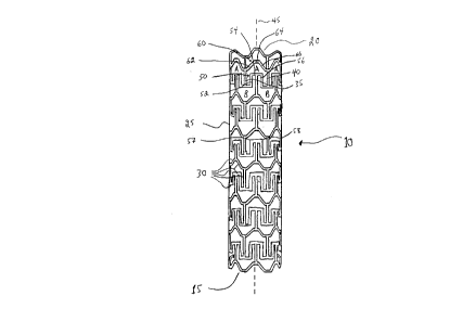
With reference to Figures 1, there is illustrated a stent 10. Stent 10
comprises a proximal end 15 and a distal end 20. Stent further comprises a tubular
21 7~722
wall 25 disposed between proximal end 15 and distal end 20. As illustrated,
tubular wall 25 is porous. The porosity of tubular wall 25 is defined by a plurality
of intersecting members 30. I-lL~ ,li lg members 30 define a first repeating
pattern ~ n~fl~d A in Figure 1.
As illustrated and with further reference to Figure lA, repeating pattern A
is a polygon ~ illg a pair of side walls 35,40. Side walls 35,40 are
sllhst~nfi~lly parallel to a longihudinal axis 45 of stent 10. Side walls 35,40 are
connected by a concave-shaped wall 50 and a convex-shaped wall 60.
As illll~fr~t~-1 concave-shaped wall 50 is made up of a trio of
segments 52,54,56. In the illustrated ~Illbudi~ l-L, segment 54 is the apex of
concave-shaped wall 54. As is evident, segment 54 is a flat apex and results in the
provision of a pair of sllh~t~h~lly square shoulders 57,58 Convex-shaped wall 60is made up of a trio of segments 62,64,66. In the illustrated embodiment,
segment 64 is the apex of convex-shaped wall 60.
It will be a~pl~ ted by those of skill in the art that the provision of first
repeating pattern A, as illll~fr~t~1 necessarily defines and provides for a second
repeating pattern B. It will also be appreciated by those of skill in the art that
second repeating pattern B is a mirror irnage of first repeating pattern A taken along
an axis (not shown) ~IIhct~nfi~lly normal to lon~ihlrlin:ll axis 45. Thus, in the
illustrated embodiments, adjacent rows of repeating pattern A and repeating pattern
B may be considered to by interlocking polygons or "arrowheads".
It will be further appreciated by those of skill in the art that the shape of
concave-shaped wall 50 and/or convex-shaped wall 60 can be modified without
departing from the function and p~.ro~ all~ of the stent provided that at least one
2s of concave-shaped wall 50 and convex-shaped wall 60 retain a substantially flat
apex. For example, the trio of segments can be replaced by a suitably curved or
-12-
21 75722
arcuate wall. Alternatively, more than three segments can be used to deflne
conc~ve-shaped wall 50 and/or convex-shaped wall 60. Other modifications will
be apparent to those of skill in the art.
It will be further appreciated by those of skill in the art that various walls of
first repeating pattern A and second repeating pattern B may be omitted (and even
desired) at selected points along the body of the stent without departing from the
spirit and scope of the invention. For example, it is possible to omit one or both
of side walls 35 and 40 at selected points along the body of the stent with a view to
improving the lon~ihl(1in~1 nexibility of the stent. Further, it is possible to omit one
or more of segments 62,64,66 at selected points along the body of the stent with a
view to improving the lateral flexibility of the stent.
Still further, the stent depicted in Figure 1 can be modified to omit, on a
selected basis, first repeatin~ pattern A and/or second repeating B with a view to
improve flexibility of the stent and to allow access to other structures (e.g. side
IS branches/arteries) outside the bounds of the stent.
With reference to Figures 2-8, there are illustrated a number of preferred
embodirnents of repeating pattern A. For the sake of clarity, numerals in Figures
2-8 have the same final two digits as the corresponding numerals in Figure 1.
Thus, for example, the concave-shaped wall is depicted as element 50 in Figure 1,
element 150 in Figure 2, element 250 in Figure 3, etc.
Thus, as illustrated in Figure 2, repeating pattern A is comprised of a
concave-shaped wall 150 and a convex-shaped wall 160, the former having a flat
apex. Further, as illustrated, concave-shaped wall 150 and convex-shaped wall 160
are not e~ ict~nt along an axis orthogonal to the lon~ihl-lin:31 axis of the stent (not
shown). Thus, in this embodiment, the flat apex in concave-shaped wall 150 has
-13-
21 75722
been modified such that it comprises a pair of sllhgt~nti~lly rounded shoulders
157, 15~.
With reference to Figure 3, repeating pattern A is similar to the one
illustrated in Figure 1. In Figure 3, the flat apex of concave-shaped wall 250 has
S been modif1ed to provide a pair of rounded shoulders 257,258. Further, a strut 270
has been added to comnect segment 254 of concave-shaped wall 250 and segment
264 of convex-shaped wall 260. As illustrated, strut 270 is thinner in drmensionthat any of the segments making up concave-shaped wall 250 and convex-shaped
wall 260. Thus, strut 270 may be considered as a relatively thin retention wire
10 which reconciles the need for retaining flexibility in the strut with mitigating lifting
of rounded shoulders 257,258 when the stent is delivered to the target body
passageway through a relatively tortuous route.
With reference to Figure 4, repeating pattern A is similar to the one
illustrated in Figure 1. In Figure 4, the flat apex of concave-shaped wall 350 has
15 been rnodified to provide a pair of rounded shoulders 357,358. Further, a curved
strut 370 has been added to connect segment 354 of concave-shaped wall 350 and
segment 364 of convex-shaped wall 360.
With reference to Figure 5, repeating pattern A is similar to the one
illustrated in Figure 1. In Figure 5, the flat apex of concave-shaped wall 450 has
20 been modified to provide a pair of rounded shoulders 457,458. Further, a curved
strut 470 has been added to commect segment 454 of concave-shaped wall 450 and
segment 464 of convex-shaped wall 460. Further, side walls 435,440 are also
curved.
With reference to Figure 6, repeating pattern A is similar to the one
25 illustrated in Figure 1. In Figure 6, concave-shaped wall 550 has been modified to
have a flat apex 554 having a pair of rounded shoulders 557,558 and convex-shaped
-14-
2I 7~722
wall 560 has been modified also to have a flat apex 564 having a pair of roundedshoulders 567,568. Further, a curved strut 570 has been added to connect flat apex
554 of concave-shaped wall 550 and flat apex 564 of convex-shaped wall 560.
Further, side walls 535,540 are also curved.
With reference to Figure 7, repeating pattern A is similar to the one
illustrated in Figure 1. In Figure 7, concave-shaped wall 650 has been modified to
have a flat apex 654 having a pair of rounded shoulders 657,658 and convex-shaped
wall 660 has been modified also to have a flat apex 664 having a pair of roundedshoulders 667,668. Further, a curved strut 670 has been added to connect flat apex
654 of concave-shaped wall 650 and flat apex 664 of convex-shaped wall 660.
Further, side walls 635,640 are also curved. Still further, walls 661,662 which
connect flat apex 664 to side walls 635,640, respectively, and walls 651,652 which
connect flat apex 654 to side walls 635,640, respectively, are each curved. It is
believed that this design even further enhances the lateral flexibility of the stent.
With reference to Figure 8, repeatmg pattern A is similar to the one
illustrated im Figure 1. In Figure 7, concave-shaped wall 750 has been modified to
have a flat apex 754 having a pair of rounded shoulders 757,758 and convex-shaped
wall 760 has been modified also to have a flat apex 764 having a pair of roundedshoulders 767,768. Further, a strut 770 has been added to connect flat apex 754
of concave-shaped wall 750 and flax apex 764 of convex-shaped wall 760. Further,side walls 735,740 have been modified to include a sinusoidal (or S-shaped) portion
736,741, respectively, adjacent convex-shaped wall 760. Further, strut 770 has
been modified to include a sinusoidal (or S-shaped) portion 771 adjacent flat apex
of concave-shaped wall 750. It is believed that this design even further enhances
the lateral flexibility of the stent.
-15-
21 75722
.
The advantages of the various alternate ~ budill-~ illustrated in Figures
2-8 are discussed herein above.
Those of skill in the art will recognize that it is possible to combine various
of the alternate embodiments illustrated in Figures 2-8 to derive furtller designs
5 whicll are still withm the spirit and scope of the present invention. Specifically, a
preferred emh~lim~nt of the present invention involves combining various of the
repeating patterns illustrated in Figures 2-8 to achieve a stent with relatively flexible
and rigid regions, for example, as follows:
F-R
F-R-F
R-F-R
wherein F is a relatively flexible region and R is a relatively rigid region. With
15 reference to the embodiments illustrated in Figures 1-7, the relatively flexibility
thereof increases (or the relative rigidity thereof decreases) from the design
illustrated in Figure 1 progressively through to the design illustrated in Figure 7.
A particularly preferred ~Il.bodi ll~llL of the invention is a stent ~UIII~ lg a first
section illCullJul~lillg the design of Figure 6 and a second section ilI~;Ol~lUldlillg the
20 design of Figure 7. It is believed that such a multi-sectional design provides a very
desirable combination of lateral flexibility (primarily from the design of Figure 7)
with post-expansion rigidity (primarily from the design of Figure 6).
Another technique by which the relative flexibility/rigidity may be varied
along the length of the stent mvolves varying the thickness of the segments making
25 up the polygon discussed hereinabove. Specifically, the thickness of the segments
may be varied in the range of from about 0.0015 to about 0.0045 inches, preferably
-16-
2175722
from about 0.0020 to about 0.0040 inches. The lower the thickness in this range,the more flexible the resultirlg stent design. Conversely, the higher the thickness
in this range, the less fle~ible the resulting stent design. Thus, by judicious
selection of segment thickness, the relative flexibility/rigidity of the stent may be
5 varied along its length.
The provision of a stent with a variable relative flexibility/rigidity along itslength is believed to be novel. Such a stent would fnd immediate use in a numberof applications. For, example, such a stent would very desirable for implantation
in an ostial stenosis (these typically occur in coronary arteries, vein grafts and renal
10 arteries). In this regard, an ostial stenosis is illustrated in Figure 9 hereof. Thus,
there is illustrated a right coronary cusp 105, a right coronary artery 110 and an
ostial segment 115 of right coronary artery 110. As further illustrated a stenosis
120 presents a narrowing of ostial segment 115. Ideally, a stent capable of
irnplantation into such an ostial stenosis must be of sufficient rigidity after
15 expansion to resist the elastic recoil of the ostial blockage (Region Y in Figure 9).
However, a stent of such sufficient rigidity will be deficient since it will either: (i)
be retarded in its advance along the artery due to the sharp bend in the right
coronary artery (Region X in Figure 9); or (ii) traverse the sharp bend in the right
coronary artery but sllhs~ ntly straighten Region X of right coronary artery 11020 thereby increasing the likelihood of tearing the artery. Conversely, a stent of
sufficiently flexibility to traverse the sharp bend m the right coronary artery (Region
X in Figure 9) is ~,u~ to recoil in the ostial right coronary artery (Region Y
in Figure 9). Accordingly, to the knowledge of the Applicant, there is no known
effective manner by which a stent may be used to treat an ostial stenosis of the type
25 illustrated in Figure 9. rt is believed that a stent having variable relative
-17-
2175722
rigidity/flexibility along its length as discussed above is a novel means by which an
ostial stenosis may be treated.
The manner by which the present stent is m~mlf~rlllred is not particularly
restricted. Preferably, the stent is produced by laser cutting techniques applied to
5 a tubular starting material. Thus, the starting material could be a thin tube of a
metal or alloy (non-limiting examples include stainless steel, titanium, tantalum,
nitinol, Elgiloy, NP35N and mixtures thereof) which would then have sections
thereof cut out to leave repeating pattern A discussed above. Thus, the preferred
design of the present stent is one of a tubular wall which is distinct from prior art
10 wire mesh designs wherein wire is C~/llrullllCd to the desired shape and welded in
place. The preferred tubular wall design of the present stent facilitates production
and improves quality control by avoiding the use of welds and, instead, utilizing
specific cutting ~rhniqurc
Stent 10 can be implanted using a conventional system wherein a guidewire,
15 catheter and balloon can be used to position and expand the stent. Il-lL,la-lLdli~ll of
mono-tubular stents such as stent 10 is conventional and within the purview of aperson skilled in the art. See, for example, any one of United States patents
4,733,665, 4,739,762, 5,035,706, 5,037,392, 5,102,417, 5,147,385, 5,282,824,
5,316,023 and any of the references cited therein or any of the references cited20 hereinabove. When the present stent is ~:o~Llu~ d as a bifurcated stent, to may be
implanted using the procedure outlined in the '997 patent application incorporated
herein by reference. Such a bifurcated stent may be ",~".1 r~ d, inter alia, by
any of tlle methods disclosed m the Canadian patent application filed in Applicant's
name on even date herewitll, the contents of which are hereby incorporated by
25 reference.
-18-
217~722
It will be apparent to those of skill in the art thdt implantation of stent 10 can
be a~;cu~ d by various other means. For example, it is cu~ ldl~.l that the
stent can be made of a suitable material which will expand when a certain
L~ Cla~ulti iS reached. In this embodiment, the material may be a metdl alloy (e.g.
S nitinol) capable of self-expansion at a t~lllLJ~laiUl~ of at least about 30~C, preferably
in thc~ range of from about 30~ to about 40~C. In this wllbodilll~llL, the stent could
be implanted using a conventional catheter and Lhe radially outward force exerted
on the stent would be generated within the stent itself. Further, stent 10 can be
designed to expand upon the application of ~P. i,~"i. ~I forces other than those10 applied by a balloon/catheter. For example, it is possible to implant stent 10 using
a catheter equipped with a resisting sleeve or retdining membrane which may thenbe removed with the catheter once the stent is in position thereby allowing the stent
to expand. Thus, in this example, the stent would be resiliently ~ulllL~ sed andwould self-expanded once the (;ull~ ive force (i.e. provided by the sleeve or
15 membrane) is removed.
As will be ~ cidL~d by those of skill in the art, repeating pattern A has
been described hereinabove and illustrated rn Figure l in respect of a monotubular
stent. Repeating pattern A and all of the features relating thereto illustrated rn and
described with reference to Figures 1-8 is equally applicable to a bifurcated stent
20 such as the one described and illustrated in the '997 application discussed
hereinabove, the contents of which are hereby i.l~lp~JldL~d by reference.
While this invention has been described with reference to illustrative
embodiments, this description is not intended to be construed in a limiting sense.
Various m~lifi~ti~nc of the illustrative ~l-lb~di l.~L~, as well as other embodrments
25 of the invention, will be apparent to persons skillcd in the art upon reference to this
-19-
217~722
description. It is therefore co-lL~ ,L~d that t~le appended claims will cover any
such mo~lifir~ion~ or embodiments.
-20-