Note: Descriptions are shown in the official language in which they were submitted.
950511 P:\1635020.DOC SI'/LW
217586~
AN INLET VALVE FOR AN AIR DRIER
Techn;c~l F;el~
The present invention relates to an inlet valve for
an air drier, preferably for a vehicle compressed air sys-
tem, between an inlet from a compressor and an inlet bore,
comprising an axially movable valve element, a spring for
biasing the valve element into a closing position against a
seat, and a valve element shoulder, on which the pressure
in the inlet is arranged to act in a valve opening direc-
tion.
B~ckgro1ln~ of the InvPnt;on
An inlet valve of the above type, also called a turbo
protection valve, is to be used in a certain compressed air
system for preventing air from the compressor from entering
the air drier, unless it has reached a certain pressure.
In certain instances it is desired to "isolate" the
air drier from the system, i e to close the inlet to the
air drier and at the same time to allow separately admitted
air under pressure to flow backwards from the system to the
compressor (by-passing the air drier).
The I~v~nt;on
The above valve, which is supplied as a separate
unit, may be built-into the air drier and according to the
invention be modified for performing the above function in
such a way that a sealing on the valve shoulder is in the
form of a U-sealing allowing air under pressure admitted to
the underside of the valve element for urging the latter in
a valve closing direction to pass the sealing to the inlet
but preventing flow in the opposite direction.
The Dr~wings
The invention will be described in further detail be-
low under reference to the accompanying drawings, in which
Fig l is an overview of a certain compressed air system,
Fig 2 is a section through a prior art valve in the system
950511 P:\1635020.DOC SP/LW
2 2175864
of Fig 1, Figs 3 and 4 are diagrammatic illustrations of
valve functions, Fig 5 is a section through a prior valve,
and Fig 6 is a section of a valve according to the inven-
tion.
S ~et~;le~ Descr;pt;on of ~ Preferre~ ~mho~;m~nt
A core element in a compressed air system, primarily
for a heavy road vehicle, shown in Fig 1 is an air drier 1.
This air drier 1 is per se known and is accordingly not
further described. Compressed air is supplied to this air
drier 1 from a compressor 2 through an inlet air conduit 3.
Dried and cleaned air is fed from the air drier 1 to a
supply tank 4 through an outlet conduit 5 and further from
this tank 4 to reservoirs 6 and 7 for use in the vehicle.
The reservoirs 6 and 7 are provided with check valves
S 8 and 9, respectively, for preventing back-flow, when the
pressure in the supply tank 4 becomes lower than in the
reservoirs 6 and 7.
A governor 10 receives a pressure signal from the
supply tank 4 through a pipe 11. The governor 10 is also
connected to the compressor 2 through a pipe 12, the air
drier 1 through a pipe 13 and a so called isolation valve
14 - to be described - through a pipe 15.
When the system has operated a certain time, so that
air delivered from the compressor 2 and dried by passage
2s through the air drier 1 has filled the supply tank 4 and
the reservoirs 6 and 7, the pressure in the supply tank 4
will rise to a certain level for influencing the governor
10 to transmit an unloader-signal to the compressor 12, the
air drier 1, and the isolation valve 14.
Dried air will now be allowed to flow back from the
supply tank 4 through the outlet conduit 5 to the air drier
1 for regenerating the desiccant bed therein.
The compressor 2 used in this system is of a type
which requires the system pressure, i e the pressure in the
supply tank 4, to be applied against the compressor heads
95051~ P:\1635020.DOC SP/LW
` `- 3 217586~
during unloading. The main purpose of the isolation valve
14 is to accomplish this.
As shown in Fig 1, the isolation valve 14 (arranged
in the inlet conduit 3) is not only connected to the gover-
S nor 10 through the pipe lS but also to the outlet conduit 5through a pipe 16, provided with a check-valve 17 for
preventing air flow from the isolation valve 14 to the out-
let conduit 5 (by-passing the air drier 1).
The isolation valve 14 is shown in section in Fig 2.
I0 The valve 14 has an internal shuttle 18, which in Fig 2 is
shown in its normal, operative position allowing incoming
air from the conduit 3 to the left in the drawing to flow
through the valve and further to the air drier 1 through
the conduit part 3 ' (but also to reach the pipe 16) .
IS The governor signal through the pipe 15 will lift the
shuttle 18 against its upper seat, so that the air drier 1
becomes isolated and air from the supply tank 4 is allowed
to flow past the check-valve 17 through the pipe 16 and
further to the compressor heads.
Fig 5 shows an earlier known, so-called turbo protec-
tion valve 20 to be mounted by means of an external thread
20' in an air inlet opening of an air drier in an installa-
tion where a certain air pressure is maintained in the in-
let conduit to the air drier, even if the compressor is
2s idle. This turbo protection valve 20 has an axially movable
valve element 21, which is biased against a seat 22 at the
inlet to the air drier by a compression spring 23 supported
by a cover 24 attached at the lower end of the valve 20.
At its side the valve 20 is provided with an inlet 25
from the compressor. Air admitted through the inlet 25 acts
on a ring-shaped shoulder 21' of the valve element 21,
which is1provided with a sealing O-ring 26 below this
shoulder. Only when the pressure acting on the shoulder 21'
exceeds the force from the spring 23 and the possible air
950511 P:\1635020.DOC SP/LW
2175861
pressure above the valve element 21, the valve 20 will
open.
A turbo protection valve 20 is schematically
illustrated in Fig 3, whereas Fig 4 in a similar manner
illustrates an isolation valve 14.
It is often desirable to have an isolation valve of
the kind shown in Fig 2 built into the air drier 1 for ob-
taining an integrated design. Based on the design of the
turbo protection valve 20 of Fig 5, it is possible to de-
sign a built-in isolation valve in accordance with Fig 6.
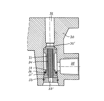
Reference numeral 30 denotes an integral bottom part
of an air drier of the type shown in Fig 1. A valve element
31 is axially movably arranged in an enlarged portion of an
inlet bore 32. A cover 33 is attached in the lower part of
this bore below the valve element 31, and a compression
spring 34 is arranged between the valve element 31 and the
cover 33 for biasing the valve element 31 against a seat
30'. The cover 33 is provided with a threaded hole 33' for
connection of the pipe 15 from the governor 10.
In front of the valve element 21 the air drier bottom
part 30 is provided with an inlet 35 for connection to the
inlet conduit 3. Under the level for the inlet 35, the
valve element 31 has a ring-shaped shoulder 31', on which a
U-sealing 36 is arranged. The U-sealing 36 is held in pro-
per position on the shoulder 31' by means of a locking ring
37.
In normal operation air is admitted through the inlet
35 from the compressor 2. The valve element 31 is depressed
against the bias of the spring 34 by the pressure acting on
the shoulder 31', so that air can flow past the valve seat
30' into the inlet bore 32. If the pressure in the inlet 35
decreases, the valve will function exactly as the turbo
protection valve 20, described above under reference to Fig
6.
950511 P:\1635020.DOC SP/I;W ' 2 1 7 5 8 6 4
When an unloader signal is received from the governor
10 (Fig 1) through the hole 33' in the cover 33, the air
pressure will act on the underside of the valve element 31
and assist the spring 34 in keeping the valve element 31
S sealingly against the seat 30', so that the air drier is
isolated from the inlet conduit 3 connected to the compres-
sor 2. Also, air under the unloader signal pressure can
pass the outer circumference of the shoulder 31', which has
a smaller diameter than the bore in which it is axially
movable. Due to the shape of the U-sealing 36 air can pass
the sealing in this direction and reach the inlet 35 for
transfer to the compressor 2.
In normal operation, when no unloader signal is pre-
sent in the hole 33 and air passes the valve from the in-
let 35 to the inlet bore 32, the U-sealing 36 will effecti-
~vely seal against its bore.
The U-sealing 36 will accordingly act as a check-
valve corresponding to the check-valve 17 in the arrange-
ment according to Fig 1.
If the isolation valve function is not needed, the
hole 33' is closed with the exception of a small venting
passage for the compartment under the valve element 31. The
valve will hereby function as the turbo protection valve 20
of Fig 5.