Note: Descriptions are shown in the official language in which they were submitted.
~ 1 ~5~4 6
APPARATUS FOR SENSING THE SPEED
OF A ROTATING ~ R~NT
RELATED APPLICATIONS
This is a continuation-in-part of co-pending
application serial number 08/467,576, filed June 6,
1995 .
BACKGROUND OF INVENTION
The invention relates to speed sensors and
particularly to a speed sensor for detecting the
rotational velocity of a rotating element. Speed
sensors are used in many applications to detect the
speed of a rotating element. In particular, they have
been used in wheel end housing or bearing assemblies of
vehicles to detect the speed of the rotating wheels
supporting the vehicle. Additionally, speed sensors
have been used in transmissions for automobiles and
trucks to detect the rotational velocity of various
rotating elements within the transmission. These
transmissions are typically an extremely complex
arrangement of gears and linkages that operate as part
o, the drive train of a vehicle to transmit power from
the engine of the vehicle to the wheels of the vehicle.
Transmissions often include a number of rotating
cylindrical members concentrically mounted within one
21 75946
another for rotation about a common axis. The
cylindrical members generally have formed therein one
or more apertures that allow lubricating fluid to
circulate through the transmission.
s
_3- 21 7~q~
SUMMARY OF THE INVENTION
Because these rotating cylinders or members in the
transmission are generally made of ferromagnetic
materials, detecting the rotational speed of the inner
cylinder using conventional ~ariable reluctance speed
sensors is difficult, if not impossible. This is
because, when the apertures of the outer rotating
cylinder are between the sensor and the inner rotating
cylinder, the sensor does not generate a flux path
having sufficient power to bridge the gap between the
sensor and the inner member. Alternatively, when the
material between the apertures of the outer cylinder is
between the sensor and the inner cylinder, that
material provides a short circuit to the magnetic flux
path generated by the sensor and prevents the magnetic
flux from reaching the inner rotating cylinder.
Accordingly, the invention provides in the
transmission of an automobile, an inner rotating member
or cylinder having a surface anomaly and an outer
rotating member having an interior surface adjacent the
inner member and having an exterior surface. The outer
member includes a plurality of apertures extending
between the interior surface and the exterior surface
of the outer member. A speed sensor having a sensor
head is mounted adjacent the exterior surface of the
outer member so as to generate a flux path extending
through at least one of the apertures in the outer
member. The flux path extends to the inner member such
~4~ 21 7~6
that rotation of the inner member relative to the
sensor generates a variation in the reluctance of the
flux path.
In one form of the invention, viewing a plane
S perpendicular to the axis of rotation of the rotating
members, the apertures in the outer member are evenly
spaced about the member on opposite sides of the plane
such that every other aperture is on the opposite side
of the plane. The sensor head extends across the plane
so that, as the outer member turns relative to the
sensor, at least one aperture of the outer member is
always exposed to the sensor. Thus, the flux path from
the sensor to the inner member is never completely
shorted by the outer member.
In another form of the invention, the apertures in
the outer member are evenly spaced about the member and
are aligned with the plane perpendicular to the axis of
rotation of the rotating members. The sensor head is
rotated 90 degrees from the sensor head described above
so that the pole pieces of the sensor head are aligned
with the plane. The pole pieces are spaced apart from
eac~, other a predetermined distance so that or.e Gf the
pole pieces is always exposed to the inner member
through one of the apertures in the outer member.
The inner member includes an exterior surface and
a surface anomaly on the exterior surface. The anomaly
may be a change in the physical structure of the
exterior surface or may be a change in the material
~5~ 21 75~46
composition of the exterior surface of the inner
member. Any change or anomaly is suitable as long as
it produces a change in the reluctance of the exterior
surface to an applied magnetic flux. In one form of
the invention, the anomaly includes a tone ring having
a plurality of radially extending teeth evenly spaced
about the exterior surface of the inner member. As the
inner member rotates relative to the speed sensor, the
passage of the teeth on the inner member past the
sensor generates a high frequency, small scale change
in the reluctance of the member cylinder to the flux
path. The frequency of this change in reluctance is
directly related to the rotational speed of the inner
cylinder and the reluctance change results in a high
frequency, low amplitude variation in the electrical
output signal of the sensor. In another form, a
magnetic tone wheel having regions of alternating
polarity as mounted on the inner member. As the inner
member rotates past the sensor, the alternating
polarity of the magnetic regions creates an alternating
flux field around the sensor that generates a high
frequency, low amplitude variation in the output of the
sensor.
As the outer member rotates relative to the speed
sensor, the passage of the spaced apertures past the
speed sensor generates a low frequency, large scale
change in the reluctance of the outer member to the
flux path. The frequency of this change in reluctance
-6- 21 75~46
is directly related to the rotational speed of the
outer member, and the low frequency change in the
reluctancè generates a low frequency, high amplitude
variation in the electrical output signal of the speed
sensor. The high frequency, low amplitude output
variation and the low frequency, high amplitude output
variation form separate and divisible components of the
electrical output signal generated by the sensor.
Using electronic signal conditioning circuitry, the
output signal of the sensor can be electronically
manipulated to separate the electrical components of
the output signal and thereby allow detection of the
rotational speed of the inner rotating member and the
rotational speed of the outer rotating member.
A principal advantage of the invention is the
provision of a transmission having a speed sensor
capable of detecting the rotational speed of an inner
member rotating inside a rotating outer member.
Another advantage of the invention is the
provision of a transmission requiring only a single
sensor fcr detecting the rotational speed of both the
inner rotating member and the outer rotating membe..
Other features and advantages of the invention are
set forth in the following detailed description and
claims.
_7_ 2 1 7~ 4 ~
BRIEF DESCRIPTION OF THE DRAWINGS
FIGURE 1 is a side-elevational view of a vehicle,
illustrating in phantom the drive train of the vehicle.
FIGURE 2 is a partial exploded perspective view of
a portion of one embodiment of the transmission
incorporated in the drive train of the vehicle shown in
Fig. 1.
FIGURE 3 is a partial schematic representation of
a portion of the transmission of Fig. 2 showing the
rotating members of the transmission in a first
position.
FIGURE 4 is a view similar to Fig. 3 and showing
the rotating members of the transmission in a second
position.
FIGURE 5 is a view similar to Fig. 3 and showing
the rotating members of the transmission in a third
position.
FIGURE 6 is a view similar to Fig. 3 and showing
the rotating members of the transmission in a fourth
position.
FIGURE 7 is a partial schematic view of components
shown in Fig. 2 and showing the sensor adjacent the
outer surface of the outer rotating member of the
transmission.
FIGURE 8 is a view similar to Fig. 7 illustrating
another embodiment of the transmission, which
embodiment includes a magnetic tone wheel.
-8- ~ 7~4~ K~
FIGURE 9 is an end view of the magnetic tone wheel
of Fig. 8 showing the polar orientation of the magnetic
regions on the magnetic tone wheel.
FIGURE 10 is an electronic schematic view of the
S sensor shown in Fig. 8 showing an electronic filter
connected thereto.
FIGURE 11 is a partial schematic representation of
a portion of the transmission of Fig. 8 showing the
rotating members of the transmission in a first
position.
FIGURE 12 is a view similar to Fig. 11 and showing
the rotating members of the transmission in a second
position.
FIGURE 13 is a view similar to Fig. 11 and showing
the rotating members of the transmission in a third
position.
FIGURE 14 is a view similar to Fig. 11 and showing
the rotating members of the transmission in a fourth
position.
FIGURE 15 is a partial end view of another
embodiment of the transmission.
FIGU~E 16 is a view taken along line 16-16 ~n Fig.
15 .
Before one embodiment of the invention is
explained in detail, it is to be understood that the
invention is not limited in its application to the
details of the construction and the arrangements of the
components set forth in the following description or
9 21 7~46 ~
illustrated in the drawings. The invention is capable
of other embodiments and of being practiced or being
carried out in various ways. Also, it is to be
understood that the phraseology and terminology used
herein is for the purpose of description and should not
be regarding as limiting.
-lo- ~1 759~6 ~
DESCRIPTION OF THE PREFERRED EMBODIMENT
Shown in Fig. 1 of the drawings is a vehicle 10.
While the vehicle 10 shown is an automobile, the
vehicle may be an automobile, truck, train, golf cart,
or any other vehicle that employs a power plant or
engine and a drive train having rotating elements
connected to the engine. Fig. 1 illustrates an engine
14 and a portion of drive train 18 of the vehicle 10.
The drive train 18 includes a transmission 22 for
transmitting power from the engine 14 of the vehicle 10
to the wheels 26 to propel the vehicle 10 along the
surface on which the vehicle 10 is supported.
While the invention is shown and described in
terms of its application in the transmission 22 of a
vehicle 10, it should be understood that the invention
could be employed in any application or construction
where it is desirable to measure the rotational speed
of one rotating element that is rotating within another
rotating element.
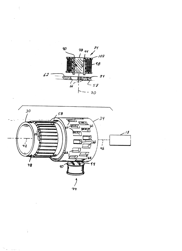
As shown in Fig. 2 the transmission 22 includes an
inner rotating member, drum, or cylinder 30 and an
outer rotating member, drum or cylinder 34. The inner
member 30 and the outer member 34 are sho~l in exploded
relation with the inner member 30 offset from its
normal operating position within the outer member 34.
The members 30 and 34 are supported by a housing 38
shown in Fig. 1 only. The inner member 30 is mounted
within the transmission 22 for rotation about an axis
-11- 21 75~4~ ~
42. The inner member 30 is connected to the drive train
18 of the vehicle 10 via a linkage 46 (shown
schematically in Fig. 2). While the inner member 30
can be made of any suitable material, in the embodiment
shown in Fig. 2, the inner member 30 is a generally
cylindrical aluminum drum. The inner member 30 has an
outer surface 48. The outer surface 48 includes a
plurality of surface anomalies or variations 50 that
are evenly spaced around the circumference of the outer
surface 48. While any surface variations that exhibit
a change in the reluctance of the inner member 30 to
flux are acceptable, in the embodiment shown in Fig. 2,
the surface variations 50 are a plurality of radially
extending teeth formed on a tone wheel 54 which is
press fitted onto the rotating aluminum inner member
30.
The outer member 34 is also supported by the
housing 38 for rotation about the axis 42. The outer
member 34 surrounds the inner member 30, that is, is
concentric to the inner member 30 and is connected to
the drive train 18 via the linkage 46. While the outer
member 34 can be made of any suitable ferromagnetic
material, the outer member 34 shown in Fig. 2 is made
of low carbon steel. The outer member 34 includes an
inner surface 58 facing the outer surface 48 of the
inner member 30, an outer surface 62, and a plurality
of apertures 66 extending between the inner surface 58
and the outer surface 62. The outer member 34 is
-12- 217~946
generally cylindrical and the apertures 66 are evenly
spaced about the circumference of the outer member 34
such that every other one of the apertures 66 iq on one
side of a plane 70 (shown as a line 70 in Figs. 3-6)
that is transverse to the axis 42 of rotation and so
that the other of the apertures 66 are on the opposite
side of the plane 70. Stated alternatively, the
apertures 66 form two rows of circumferentially spaced
apart rectangular apertures, the rows being
longitudinally spaced and on opposite sides of plane
70. When the inner member 30 is positioned within the
outer member 34, the teeth 50 extend across the plane
70 so that they span both rows of apertures 66 in outer
member 34.
As shown in Figs. 3-7, the transmission 22 further
includes a sensor 74 mounted on the housing 38 adjacent
the outer surface 62 of the outer member 34. The
sensor 74 is a variable reluctance speed sensor. The
sensor 74 includes a magnet 78 havi~g magnetically
opposite poles 82 and 86 (or N and S in Fig. 7) and
includes pole pieces 90 and 94 mounted on the poles,
respectively. As shown in Figure 7, the senso- 74 also
includes an inductive coil 98 that is wound around a
generally plastic bobbin 102. The coil 98 and bobbin
102 surround the magnet 78 and pole pieces 90 and 94 so
that the magnetic flux generated by the magnet 78
generates a corresponding electrical current signal in
the coil 98. The coil 98 includes a pair of leadwires
-13- 2115~46
(not shown) that are connected to a signal conditioning
circuit (not shown) for processing the electrical
signal generated by the magnetic flux.
In operation, as the inner member 30 rotates, the
surface anomalies or teeth 50 rotate past the speed
sensor 74 causing a high frequency, small scale
variation in the reluctance of the inner member 30 to
flux. The variation in reluctance to flux generates a
high frequency, low amplitude variation in the
electrical signal generated on the coil 98 of the
sensor 74. The frequency of the signal is directly
related to the rotational speed of the inner member 30.
Likewise, as the outer member 34 rotates relative
to the speed sensor 74, the passage of the spaced
apertures 66 past the speed sensor 74 generates a low
frequency, large scale variation in the reluctance of
the outer member 34 to flux which, in turn, causes a
low frequency, high amplitude change in the electrical
output signal of the speed sensor 74. The high
frequency, low amplitude output variation and the low
frequency, high amplitude output variation form
separate and divisible components of the electrical
output signal generated by the sensor 74. The output
signal of the sensor 74 can be electronically
manipulated using electronic signal conditioning
circuitry to separate the individual components of the
electrical output signal and thereby allow detection of
14 ~K~
- - 2 1 75~
the rotational speed of both the inner member 30 and
the outer member 34.
While this invention can theoretically function
effectively using any number apertures 66 in the outer
member 34 and any number of teeth 50 on the inner
member 30, it has been found desirable to optimize the
number of teeth 50 and the number of apertures 66.
Specifically, if the rotational speed limits of the
inner member 30 and the outer member 34 are known, then
the number of teeth 50 on the inner member 30 and the
number of apertures 66 in the outer member 34 can be
selectively chosen to optimize the frequency of the
signal generated by the inner member 30 and the
frequency of the signal generated by the outer member
34. Optimization of the frequencies of the electrical
signal variations generated by the respective members
allows one to use standard filtering practices to
separate the signals from the composite output signal
generated by the sensor 74. Such standard filtering
practices can usually be employed using filtering
circuitry that is either conventional or that is easily
designed by one of skill in the art.
By way of example, assume that:
ZO = No. of teeth in outer member 34;
= No. of aPertures 66;
Z, = No. of teeth 50 on inner member 30;
-lS- 2~ 75946 ~
VO = Velocity of outer member 34 (Assume that
O r.p.m. ~ ¦VOl ~ ¦V1¦, (Note: velocity
is independent of direction));
V1 = Velocity of inner member 30 (Assume that
¦V1¦ > O r.p.m. (Note: velocity is
independent of direction));
fO = frequency of the signal generated by the
outermember 34;
VO x ZO
fo = (Hz);
fi = frequency of the signal generated by the
innermember 30; and
Vi x Zi
fi = (Hz).
While it is desirable that fi~;n be greater than
f~ by an order of magnitude, if, at a minimum f~ '
fi~nr then the signals of interest can be separated
using either a high pass or a low pass filter.
Separation of the frequencies by an order of magnitude
allows the use of less complicated filtering methods.
Shown in Figs. 3-6 of the drawing are schematic
representations of the flux paths ~i and ~2 that are
followed by the magnetic flux that is generated by the
magnet 78 for the various positions of the inner member
30 and outer member 34. Fig. 3 shows one of the teeth
50 of the inner member 30 aligned with the sensor 74
and an aperture 66 in the outer member 34 located on
the left side (as shown in Fig. 3) of the plane 70
orientated or aligned with the sensor 74. In this
-16-
21 75~6
state, flux generated by the magnet 78 will flow (as
shown by the representation of flux path ~l) f rom the
pole piece 94 through the material comprising the outer
member 34 on the right side of the plane 70 and back to
the pole piece 90 of the sensor 74. Also, magnetic
flux generated by the magnet 78 will flow (as shown by
the representation of flux path ~2 ) from the pole piece
90 through the aperture 66 in the outer member 34 to
the tooth 50 mounted on the inner member 30 and through
the tooth 50, back through the portion of the outer
member 34 to the right of the plane 70 and through the
opposite pole piece 94 to complete the flux path ~2 .
Fig. 4 illustrates an operating condition
wherein, as in Fig. 3, a tooth 50 on the inner member
30 is aligned with the sensor 74. However, in Fig. 4,
the outer member 34 is positioned so that one of the
apertures 66 to the right (as shown in Fig. 4) of the
plane 70 is aligned with the sensor 74. In this
operating state, the flux path ~I now extends f rom the
pole piece 94 through the aperture 66 to the
ferromagnetic tooth 50 on the inner member 30, th,ough
the portion of the outer member 34 opposite to the
aperture 66, and to the pole piece gO. Alternatively,
the flux path ~2 now extends from the pole piece 90 to
the portion of the outer member 34 opposite the
aperture 66, and across the aperture 66 to the pole
piece 94 to complete the flux path ~2 .
-17- 21 7594~
Fig. 5 illustrates the operating state wherein the
inner member 30 is aligned so that any flux path ~l or
~2 generated by the sensor 74 is between successive
teeth S0 on the inner member 30 and wherein an aperture
66 to the left (viewing Fig. 5) of the plane 70 is
aligned with the sensor 74. In this state, the flux
path ~1 is the same as the flux path ~1 in Fig. 3.
Also, the flux path ~2 is the same as the flux path ~2
in Fig. 3 except that the reluctance of the inner
member 30 to flux is varied because, rather than being
aligned with a tooth 50 on the inner member 30, the
sensor 74 is now aligned with the gap between
successive teeth 50 on the inner member 30. This
change in the reluctance to flux causes a corresponding
change in the output signal generated on the coil 98 of
the sensor 74.
Fig. 6 illustrates an operating state similar to
that of Fig. 4 except that, as in Fig. 5, the sensor 74
is between successive teeth 50 on the inner member 30.
Therefore, the flux pathways ~l and ~2 are the same as
those shown in Fig. 4 with the exception that ~he gap
between the successive teeth 50 in the inner member 30
causes a change in the reluctance of the inner member
30 to flux and therefore a corresponding change in the
electrical signal generated on the coil 98 as a result
of the flux path ~1. It should be noted that in all of
the above cases the flux direction is a matter of
-18- 217~6 ~o~
convention and can be changed in various ways without
changing the operation of the sensor 74 itself.
In a four speed transmission, the transmission 22
typically has three operating states that generate the
S four different transmission speeds. In first gear, the
outer member 34 rotates in a direction opposite to that
of the inner member 30 and at a speed which is less
than or equal to the speed of the inner member 30. In
this state, the sensor 74 will generate an output
signal on the coil 98 that reflects the changing flux
path between the sensor 74 and the outer member 34 as
well as the changing flux path between the sensor 74
and the inner member 30.
In second gear, the outer member 34 does not
rotate, that is, it is stopped, while the inner member
30 continues to rotate. In this state, the sensor 74
will generate an output on the coil 98 that is a
reflection of the magnetic flux that is between the
sensor 74 and the inner member 30. As the inner member
30 rotates, the movement of the teeth 50 past the
sensor 74 changes the reluctance of the inner member 30
to flux and therefore alters the electrical signal
generated on the coil 98 of the sensor 74. As
discussed above, these changes in the electrical signal
are indicative of the rotating speed of the inner
member 30.
In third gear, the outer member 34 is rotating at
the same speed and in the same direction as the inner
-19- 2 1 7~46
member 30. In this state, the reluctance to flux is
changing for both flux paths, i.e., the flux path
extending from the sensor 74 to the outer member 34 as
well as the flux path extending from the sensor 74 to
the inner member 30. Therefore, the sensor 74 will
generate an electrical output that is a reflection of
the rotational speed of both the outer member 34 and
the inner member 30.
In fourth gear, the outer member 34 is again
stopped while the inner member 30 continues to rotate
and the output of the sensor 74 is similar to that of
the output generated when the transmission 22 is in
second gear.
By inputting the output of the coil 98 to an
appropriate signal conditioning circuit (which may
include a microprocessor based circuit for analyzing
the signal), the rotational speed of the outer member
34 and the rotational speed of the inner member 30 can
be detected and the operating state of the transmission
can be determined. This information can be used to
control various engine functions including electronic
shifting of the transmission.
Fig. 8 illustrate-~ a transmission 200 that is
another embodiment of the invention. Like parts are
identified with like reference numerals. The
transmission 200 includes a magnetic tone wheel 210
that is mounted (usinq any appropriate means) on the
outer surface 48 of the inner member 30. The tone
-20- 21 75q46
wheel 210 has formed therein a plurality of permanent
magnetic regions 214 (shown only in Fig. 9)
consecutively spaced about the circumference of the
tone wheel 210. Each magnetic region 214 includes a
magnetic pole pair having a north pole ("N") and a
magnetically opposite south pole ("S"). The pole pairs
alternate in polarity about the circumference of the
tone wheel 210 and define a plurality of axes 218 (only
one of which is shown in Fig. 9) extending between the
north and south poles of the respective pole pairs.
The axes 218 are perpendicular to the axis 46, i.e.,
the axes 218 extend radially outward from the axis 46.
The transmission 200 includes a sensor 222 (Fig.
8) supported by the transmission 200 adjacent the outer
surface 62 of outer member 34. The sensor 222 includes
a bobbin 226 and an inductive coil 230 wound onto the
bobbin 226. The bobbin defines a pair of apertures 234
and 236 central to the coil 230 and the sensor 222 has
a pair of ferromagnetic pole pieces 238 and 240
supported by the bobbin 226 in the apertures 234 and
236. The sensor 222 is positioned so that the pole
pieces 238 and 240 are on opposite sides of the plane
70 (Figs. 11-14). An optional pair of magnet caps 242
and 244 are shown mounted on the bobbin 226. The
magnet caps 242 and 244 enhance the electrical signal
generated on the coil 230.
In operation, as the inner member 30 rotates, the
magnetic regions 214 rotate past the speed sensor 222.
-21- 2 1 7~6 ~K~
The alternating polarities of the magnetic regions 214
on the inner member 30 generate a series of flux fields
having alternating flux path directions and the flux in
these fields passes through the region surrounding the
S sensor 222 and the sensor 222. In other words, the
direction of flux flow in the flux path surrounding the
sensor 222 changes in response to the alternating
polarities of magnetic regions 214 that are aligned
with the sensor 222. The alternating change in the
flux field generates a high frequency, small scale
variation in the electrical output of the sensor coil
230.
As the outer member 34 rotates relative to the
speed sensor 222, the passage of the spaced apertures
66 through the flux field generates a low frequency
variation in the reluctance of the outer member to
flux. This variation in turn generates a low frequency
change in the electrical output of the sensor coil 230.
The output signal of the sensor is amplitude modulated
only and therefore, the frequency optimization as
described above with respect to the embodiment shown in
Fig. 2 is not required.
Though any type of known electronic filters can ~e
employed depending upon the application and other
design criteria, fig. 10 illustrates a schematic view
of the sensor 222 and one form of a very simple
electronic filter connected thereto. The filter is a
capacitor C~ connected in parallel to the sensor 222,
-22- 2 1 7 5~46
and Rs is the internal resistance of the sensor 222, Ls
is the inductance of the sensor 222, VI~ is the
internal voltage generated by the flux field
surrounding the sensor 222, and Cs is the capacitance
of the sensor 222.
Shown in figs. 11-14 of the drawings are schematic
representations of the flux path ~ that is followed by
the flux generated by magnetic regions 214 for the
various positions of inner member 30 and outer member
34 relative to the sensor 222. Fig. 11 illustrates an
operating condition wherein the inner member 30 is
positioned so that a magnetic region 214 having an N-
pole faces the sensor 222 and an aperture 66 is located
on the left side (as shown in fig. 11) of the plane 70
oriented or aligned with the sensor 222. In this
state, flux generated by the tone wheel 210 will flow
(as shown by the representation of flux path ~) in a
counter-clockwise direction (as shown in fig. 11) from
tone wheel 210, through aperture 66 to pole piece 238,
around coil 230, through outer member 34 and back to
tone wheel 210 to complete the flux patn ~.
Fig. 12 illustrates an operating condition
wherein, as in fig. 11, a magnetic region 214 having an
N-pole is aligned with the sensor 222. However, in
fig. 12, the outer member 34 is positioned so that one
of the apertures 66 to the right tas shown in fig. 12)
of the plane 70 is aligned with the sensor 222. In
this operating po~ition, the flux path ~ now extends in
-23- 2~ 75~46 ~sx~
a clockwise direction from tone wheel 210 through
aperture 66, through pole piece 240, around coil 230,
through a portion of outer member 34 and back to tone
wheel 210 to complete the flux path ~.
Fig. 13 illustrates an operating condition wherein
the inner member 30 is positioned so that a magnetic
region 214 having a S-pole is aligned with the sensor
222 and wherein an aperture 66 to the left (viewing
fig. 13) of the plane 70 is aligned with the sensor
222. In this state, the flux path ~ is the same as the
flux path ~ followed in the condition illustrated in
fig. 11 except that the flux path followed in fig. 13
is clockwise rather than the counter-clockwise path
followed in fig. 11.
Fig. 14 illustrates an operating condition similar
to that of fig. 12 except that, as in fig. 13, the tone
wheel 210 is aligned with the sensor 222 so that a
magnetic region 214 having an S-pole is aligned with
the sensor 222. In this state, the flux path ~ is the
same as the flux path shown in fig. 12 except that the
flux path ~ in fig. 14 is oriented in a counter-
clockwise direction whereas the flux path shown in fig.
12 is oriented in a counter-clockwise direction wh~reas
the flux path shown in fig. 12 is oriented in a
clockwise direction.
Fig. 15 illustrates a transmission 300 that is
another embodiment of the invention. Like parts are
identified using like reference numerals. The
-24- 21 75'1~6
transmission 300 includes an inner member 304 and an
outer rotating member 308. Like the rotating members
30 and 34, the rotating members 304 and 308 are
supported within the transmission 300 for rotation
about the axis 42 (shown only in Fig. 2). The inner
rotating member 304 includes a plurality of magnetic
regions 312 circumferentially spaced about the rotating
member 304. The poles (N,S) of the magnetic regions
312 are radially aligned with respect to the axis 42
and the poles (N,S) of each successive magnetic region
alternate in polarity. Each pair of successive
magnetic regions is separated by a magnetically
neutral, low magnetic permeability region 316. Though
any low magnetic permeability material is appropriate,
the regions illustrated in Figure 15 are made of a
material such as plastic. The provision of a
magnetically neutral region 316 between each successive
magnetic region 312 reduces the flux transmission from
one pole (N or S) of a given magnetic region 312 from
"shorting~ to the opposite pole (S or N) of the
magnetic region 312 next to the giver. ma~netic region
312. Instead, the flux from one pole (N or S) of the
given magnetic region 312 extends first radially
outward and then "bends" around to return, through an
associated magnetically neutral region 316, to the
given magnetic region 312 at the opposite pole (S or N)
of that given magnetic region 312.
-25- 21 75946 ~x~
The outer member 308 includes an inner surface
320, an outer surface 324, and a plurality of apertures
328 extending between the inner surface 320 and the
outer surface 324. The outer member 308 differs from
the outer member 34 in that there is only one row of
apertures 328 and the apertures 328 are uniformly
centered on the plane 70 (shown only in Fig. 7).
The transmission 300 also includes a sensor 332
for receiving the magnetic field that is generated by
the magnetic regions 312 on rotating member 304, and
that extends, at least in part, through the outer
member 308 and the inner member 304. The sensor 332 is
mounted adjacent the outer surface 324 of the outer
member 308 and is substantially identical to the sensor
222. The sensor 332 includes a coil 334 and a pair of
magnetically permeable pole pieces, 336 and 340,
mounted adjacent the coil 334 and centered on the plane
70. As shown in Fig. 15, the pole pieces 336 and 340
include respective opposed, tapered end portions 344
and 348 slanting in a direction that is generally
parallel to the outer surface 324 of the outer member
308. The end portions 344 and 348 form a surface 352
that is opposed to and generally complementary with the
outer surface 324 of the outer member 308 so as to
reduce the distance across which the magnetic field
must be effective.
In operation, as the inner member 304 rotates, the
magnetic regions 312 rotate past the speed sensor 332.
-26- 2 1 / 5 9 4 6 ~#K~
The alternating polarities of the magnetic regions 312
on the inner member 304 generate a series of flux
fields having alternating flux path directions and the
flux in these fields passes through the region
surrounding the sensor 332, as well as the sensor 332.
In other words, the direction of flux flow in the flux
path surrounding the sensor 332 changes in response to
the alternating polarities of magnetic regions 312 that
are aligned with the sensor 332. The alternating
change in the magnetic field generates a high
frequency, small scale variation in the electrical
output of the sensor coil 334.
As the outer member 308 rotates relative to the
speed sensor 332, the passage of the spaced apertures
328 through the magnetic field generates a low
frequency variation in the reluctance of the outer
member 308 to flux. This variation in turn generates a
low frequency change in the electrical output of the
sensor coil 334.
Various features and advantages of the invention
are set forth in the fGllowing claims.