Language selection

Search

Patent 2176047 Summary

Third-party information liability

Some of the information on this Web page has been provided by external sources. The Government of Canada is not responsible for the accuracy, reliability or currency of the information supplied by external sources. Users wishing to rely upon this information should consult directly with the source of the information. Content provided by external sources is not subject to official languages, privacy and accessibility requirements.

Claims and Abstract availability

Any discrepancies in the text and image of the Claims and Abstract are due to differing posting times. Text of the Claims and Abstract are posted:

  • At the time the application is open to public inspection;
  • At the time of issue of the patent (grant).
(12) Patent: (11) CA 2176047
(54) English Title: SPRING LOADED ROTARY CONNECTOR
(54) French Title: RACCORD ROTATIF A RESSORT DE RAPPEL
Status: Expired and beyond the Period of Reversal
Bibliographic Data
(51) International Patent Classification (IPC):
  • H01R 39/26 (2006.01)
  • H01R 13/24 (2006.01)
  • H01R 39/64 (2006.01)
(72) Inventors :
  • SOBHANI, MOHI (United States of America)
(73) Owners :
  • HE HOLDINGS, INC. D/B/A HUGHES ELECTRONICS
  • RAYTHEON COMPANY
(71) Applicants :
  • HE HOLDINGS, INC. D/B/A HUGHES ELECTRONICS (United States of America)
  • RAYTHEON COMPANY (United States of America)
(74) Agent: MARKS & CLERK
(74) Associate agent:
(45) Issued: 2000-04-11
(22) Filed Date: 1996-05-08
(41) Open to Public Inspection: 1996-11-23
Examination requested: 1996-05-08
Availability of licence: N/A
Dedicated to the Public: N/A
(25) Language of filing: English

Patent Cooperation Treaty (PCT): No

(30) Application Priority Data:
Application No. Country/Territory Date
08/445,519 (United States of America) 1995-05-22

Abstracts

English Abstract


A rotary connector (10) comprising first and second printed wiring boards (12.
13) that rotate relative to each other and that are electrically interconnected using spring
loaded pogo-stick type contacts (22). The spring loaded contacts are used to transfer
electrical signals or power to metallized rings (15) or contacts formed on the first
printed wiring board (11). The spring-loaded pogo-stick type contacts (22) are very
rugged and provide for a rotary connector (10) having long life.


Claims

Note: Claims are shown in the official language in which they were submitted.

6
CLAIMS
What is claimed is:
1. A rotary connector comprising:
a first member having one surface thereof that has a plurality of
electrically isolated metallic rings formed thereon and wherein each ring has
a hole
disposed therethrough;
a plurality of electrical wires individually soldered to the plurality of
electrically isolated metallic rings;
a second member disposed adjacent to the first member and that is
mutually rotatable relative to the first member and that comprises a plurality
of
spring-loaded contacts disposed to engage the plurality of electrically
isolated metallic
rings of the first member; and
a plurality of electrical wires soldered to respective spring-loaded
contacts;
and wherein the spring-loaded rotary connector permits relative
angular movement between the first and second members, and compensates for
relative separational distances therebetween.
2. The rotary connector of Claim 1 wherein the first member comprises a
copper laminated phenolic ring.
3. The rotary connector of Claim 2 wherein the first member has an
opening therein for receiving a shaft.
4. The rotary connector of Claim 1 wherein the holes are plated.
5. The rotary connector of Claim 1 wherein the wires are routed to a
connector.
6. The rotary connector of Claim 1 wherein the second member
comprises a phenolic member.
7. The rotary connector of Claim 1 wherein the second member has an
opening therein for receiving a shaft.

7
8. The rotary connector of Claim 6 wherein the plurality of electrical
wires are soldered to the respective spring-loaded contacts.
9. The rotary connector of Claim 8 wherein the plurality of electrical
wires are soldered to a connector.
10. The rotary connector of Claim 1 wherein the second member
comprises a plurality of sets of spring-loaded contacts.

Description

Note: Descriptions are shown in the official language in which they were submitted.


~1'~604'~
SPRING LOADED ROTARY CONNECTOR
BACKGROUND OF THE INVENTION
The present invention generally relates to rotary connectors, and more
particularly, to an improved spring loaded connector comprising rotatable
printed
wiring boards electrically interconnected by spring loaded contacts.
The purpose of a rotary connector is to transmit power or signals from a
stationary object to a moving or rotating object. A conventional slip ring
connector is
a very fragile device. Conventional slip rings are impractical and very
wlnerable to
road hazards for use in automobile and transportation vehicles. In harsh
environments,
such as those encountered in aircraft and vehicular use, such slip ring
connectors often
fail due to the fragile nature of brushes and rings used therein.
Therefore, it is an objective of the present invention to provide for an
improved
rotary connector comprising rotatable printed wiring boards electrically
interconnected
by spring loaded contacts.

.. ° CA 02176047 1999-11-10
2
SUMMARY OF THE INVENTION
In order to meet the above and other objectives, the present invention
provides
for a spring loaded connector the uses printed wiring boards that rotate
relative to
each other that are electrically interconnected using a plurality of sets of
spring loaded
pogo-stick type contacts. In the present invention, the spring-loaded rotary
connector
pogo-stick type contacts are used to transfer electrical signals or power
between two
sets of metallized contacts formed on printed wiring boards, for example. The
spring-
loaded rotary connector pogo-stick type contacts are very rugged and provide
for a
rotary connector having long life.
Accordingly, in one aspect of the present invention there is provided a rotary
connector comprising:
a first member having one surface thereof that has a plurality of electrically
isolated metallic rings formed thereon and wherein each ring has a hole
disposed
therethrough;
a plurality of electrical wires individually soldered to the plurality of
electrically isolated metallic rings;
a second member disposed adjacent to the first member and that is mutually
rotatable relative to the first member and that comprises a plurality of
spring-loaded
contacts disposed to engage the plurality of electrically isolated metallic
rings of the
first member; and
a plurality of electrical wires soldered to respective spring-loaded contacts;
and wherein the spring-loaded rotary connector permits relative angular
movement between the first and second members, and compensates for relative
separational distances therebetween.
The present rotary connector can withstand harsh outdoor environments such
as when it is used in axles of automobiles and trucks, for example. The
present rotary
connector is designed and fabricated using spring-loaded pogo stick-type
contacts and
insulative material. The pogo-stick type contacts of the rotary connector are
sandwiched between two printed wiring boards and can withstand harsh road or
highway environment.
The present rotary connector may be used to transmit power or signals from a
stationary object to a moving object. The present rotary connector can replace

- '- CA 02176047 1999-11-10
2a
existing slip-ring type connectors currently used in many aircraft and vehicle
applications. The spring loaded rotary connector is very rugged and performs
well in
harsh outdoor environments. Two connectors have been built and tested on an
auto
axle and have met all expectations. The present invention may be used in cars
trucks
motor homes, motorcycles, and aircraft, wherever rotary electrical connectors
may be
employed.
BRIEF DESCRIPTION OF THE DRAWINGS
The various features and advantages of the present invention may be more
readily understood with reference to the following detailed description taken
in
conjunction with the accompanying drawings, wherein like reference numerals
designate like structural elements, and in which:
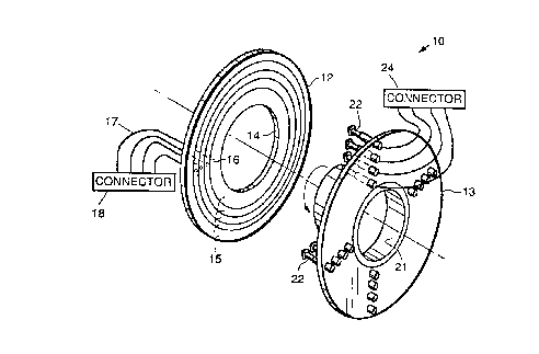
Fig. 1 illustrates an exploded perspective view of a spring loaded rotary
connector in accordance with the principles of the present invention; and

Fig. 2 illustrates a cross sectional side view of the spring loaded rotary
connector of Fig. 1.
DESCRIPTION OF THE PREFERRED EMBODIMENTS
Referring to the drawing figures, Fig. 1 illustrates an exploded perspective
view of a spring-loaded rotary connector 10 in accordance with the principles
of the
present invention. Fig. 2 illustrates a cross sectional side view of the
spring-loaded
rotary connector 10 of Fig. 1. The spring-loaded rotary connector 10 is
illustrated
with reference to its use in a shaft-type application, wherein its rotatable
components
are designed to mate with a shaft 11 that rotates relative to a fixed housing
25 or
member 25 or relative to the second member 13. However, it is to be understood
that
the present connector 10 may be readily used in other applications.
The exemplary rotary connector 10 is comprised of first and second members
12, 13 that are mutually rotatable relative to each other. As shown in Fig. I,
the first
member 12 may be comprised of a copper laminated phenolic ring 12a having an
opening 14 therein for receiving the shaft 11, that is machined (grooved) to
form a
plurality of electrically isolated metallic rings 15. Each of the rings I S
are drilled or
otherwise formed so that each ring 15 has a hole 16 therethrough. The holes 16
are
plated through to permit soldering of insulated electzical wires 17 thereto.
The holes
16 have insulated wire soldered therein on one side thereof (distal from the
second
member 13) and the wires 17 are routed to a connector 18 that provides for
connection to an external electrical signal source or power source (not
shown), for
example.
The second member 13 may comprise a phenolic plate 13a or ring 13a which
may have an opening 21 therein for receiving the shaft 11, and that is
machined to
accept a plurality of sets of spring-loaded individual pogo-stick type
contacts 22
generally mounted at equally spaced locations so that they are positioned to
engage
the plurality of electrically isolated metallic rings 15 of the copper
laminated phenolic
ring 13a or first member 13. Insulated wires 23 are soldered between
respective
bottoms of the pogo-stick type contacts 22 and a connector 24 that may be
connected
to one or more sensors (not shown), for example.

2i s ~~~"~
The pogo-stick type contacts 22 are commercially available, for example, from
Test-X Fixture Products (Riverside, California), part number TX416S2 or
TX4I6S3.
The spring-loaded rotary connector 10 permits relative angular movement
between the shaft 1 I and the housing 25 that secures the second member 13.
The
spring-loaded rotary connector 10 also compensates for movement between the
first
and second members 12, 13 in terms of their separation distance. More
specifically, if
the respective planes of the first and second members 12, 13 are not parallel,
then the
pogo-stick type contacts 22 adjust for the differences in distance
therebetween. This
may be caused by vibration of a vehicle, for example, or relative movement
between
the components that are connected to the shaft 1 l and the housing 25 to which
the
second member 13 is secured. This might be the relative movement between an
axle
and a wheel of a vehicle, for example. The relative motion is compensated for
by the
spring-loaded individual pogo-stick type contacts 22 which operate to keep
electrical
contact with the respective metallic rings I 5 irrespective of the relative
angular
relationship between the first and second members 12, 13.
The rotary connector 10 is shown as comprising flat members 12, 13 that are
designed to engage the shaft 11. However, it is to be understood that
contoured
members 12, 13 such as may be provided by cylindrical or spherical members,
for
example, may be employed as well as fiat members 12, 13. Therefore, the
present
connector 10 is not limited to a configuration that is flat.
The rotary connector 10 has been designed to withstand harsh outdoor
environments such as when it is used in axles of automobiles and trucks, for
example.
The rotary connector 10 may be used to transmit power or signals from a
stationary
object to a moving object. The rotary connector 10 has been developed to
replace
existing slip-ring type connectors currently used in many aircraft and vehicle
applications. The spring loaded rotary connector 10 is very rugged and
performs well
in harsh outdoor environments. Two connectors I O have been built and tested
on an
auto axle, and have performed well. The present invention may be used in cars
trucks
motor homes, motorcycles, and aircraft, wherever rotary electrical connectors
may be
employed.

Thus, an improved spring-loaded rotary connector has been described. It is to
be understood that the above-described embodiment is merely illustrative of
some of
the many specific embodiments which represent applications of the principles
of the
present invention. Clearly, numerous and other arrangements can be readily
devised
by those skilled in the art without departing from the scope of the invention.

Representative Drawing
A single figure which represents the drawing illustrating the invention.
Administrative Status

2024-08-01:As part of the Next Generation Patents (NGP) transition, the Canadian Patents Database (CPD) now contains a more detailed Event History, which replicates the Event Log of our new back-office solution.

Please note that "Inactive:" events refers to events no longer in use in our new back-office solution.

For a clearer understanding of the status of the application/patent presented on this page, the site Disclaimer , as well as the definitions for Patent , Event History , Maintenance Fee  and Payment History  should be consulted.

Event History

Description Date
Time Limit for Reversal Expired 2007-05-08
Letter Sent 2006-05-08
Inactive: IPC from MCD 2006-03-12
Grant by Issuance 2000-04-11
Inactive: Cover page published 2000-04-10
Pre-grant 2000-01-17
Inactive: Final fee received 2000-01-17
Letter Sent 1999-12-16
Amendment After Allowance Requirements Determined Compliant 1999-12-16
Inactive: Amendment after Allowance Fee Processed 1999-11-10
Amendment After Allowance (AAA) Received 1999-11-10
Notice of Allowance is Issued 1999-07-26
Letter Sent 1999-07-26
Notice of Allowance is Issued 1999-07-26
Inactive: Approved for allowance (AFA) 1999-06-23
Inactive: Status info is complete as of Log entry date 1998-04-20
Inactive: Application prosecuted on TS as of Log entry date 1998-04-20
Application Published (Open to Public Inspection) 1996-11-23
Request for Examination Requirements Determined Compliant 1996-05-08
All Requirements for Examination Determined Compliant 1996-05-08

Abandonment History

There is no abandonment history.

Maintenance Fee

The last payment was received on 1999-04-29

Note : If the full payment has not been received on or before the date indicated, a further fee may be required which may be one of the following

  • the reinstatement fee;
  • the late payment fee; or
  • additional fee to reverse deemed expiry.

Patent fees are adjusted on the 1st of January every year. The amounts above are the current amounts if received by December 31 of the current year.
Please refer to the CIPO Patent Fees web page to see all current fee amounts.

Fee History

Fee Type Anniversary Year Due Date Paid Date
Registration of a document 1996-05-08
Request for examination - standard 1996-05-08
MF (application, 2nd anniv.) - standard 02 1998-05-08 1998-04-20
Registration of a document 1998-09-09
MF (application, 3rd anniv.) - standard 03 1999-05-10 1999-04-29
1999-11-10
Final fee - standard 2000-01-17
MF (patent, 4th anniv.) - standard 2000-05-08 2000-04-25
MF (patent, 5th anniv.) - standard 2001-05-08 2001-04-17
MF (patent, 6th anniv.) - standard 2002-05-08 2002-04-16
MF (patent, 7th anniv.) - standard 2003-05-08 2003-04-16
MF (patent, 8th anniv.) - standard 2004-05-10 2004-04-13
MF (patent, 9th anniv.) - standard 2005-05-09 2005-04-13
Owners on Record

Note: Records showing the ownership history in alphabetical order.

Current Owners on Record
HE HOLDINGS, INC. D/B/A HUGHES ELECTRONICS
RAYTHEON COMPANY
Past Owners on Record
MOHI SOBHANI
Past Owners that do not appear in the "Owners on Record" listing will appear in other documentation within the application.
Documents

To view selected files, please enter reCAPTCHA code :


To view images, click a link in the Document Description column. To download the documents, select one or more checkboxes in the first column and then click the "Download Selected in PDF format (Zip Archive)" or the "Download Selected as Single PDF" button.

List of published and non-published patent-specific documents on the CPD .

If you have any difficulty accessing content, you can call the Client Service Centre at 1-866-997-1936 or send them an e-mail at CIPO Client Service Centre.


Document
Description 
Date
(yyyy-mm-dd) 
Number of pages   Size of Image (KB) 
Abstract 1996-08-15 1 13
Description 1996-08-15 5 180
Claims 1996-08-15 2 46
Drawings 1996-08-15 1 26
Representative drawing 1998-08-18 1 15
Representative drawing 2000-03-01 1 13
Description 1999-11-09 6 209
Claims 1999-11-09 2 45
Reminder of maintenance fee due 1998-01-20 1 111
Courtesy - Certificate of registration (related document(s)) 1998-07-02 1 140
Commissioner's Notice - Application Found Allowable 1999-07-25 1 163
Maintenance Fee Notice 2006-07-03 1 172
Correspondence 2000-01-16 1 49
Correspondence 1999-12-15 1 6