Sélection de la langue

Search

Sommaire du brevet 2176047 

Énoncé de désistement de responsabilité concernant l'information provenant de tiers

Une partie des informations de ce site Web a été fournie par des sources externes. Le gouvernement du Canada n'assume aucune responsabilité concernant la précision, l'actualité ou la fiabilité des informations fournies par les sources externes. Les utilisateurs qui désirent employer cette information devraient consulter directement la source des informations. Le contenu fourni par les sources externes n'est pas assujetti aux exigences sur les langues officielles, la protection des renseignements personnels et l'accessibilité.

Disponibilité de l'Abrégé et des Revendications

L'apparition de différences dans le texte et l'image des Revendications et de l'Abrégé dépend du moment auquel le document est publié. Les textes des Revendications et de l'Abrégé sont affichés :

  • lorsque la demande peut être examinée par le public;
  • lorsque le brevet est émis (délivrance).
(12) Brevet: (11) CA 2176047
(54) Titre français: RACCORD ROTATIF A RESSORT DE RAPPEL
(54) Titre anglais: SPRING LOADED ROTARY CONNECTOR
Statut: Périmé et au-delà du délai pour l’annulation
Données bibliographiques
(51) Classification internationale des brevets (CIB):
  • H01R 39/26 (2006.01)
  • H01R 13/24 (2006.01)
  • H01R 39/64 (2006.01)
(72) Inventeurs :
  • SOBHANI, MOHI (Etats-Unis d'Amérique)
(73) Titulaires :
  • HE HOLDINGS, INC. D/B/A HUGHES ELECTRONICS
  • RAYTHEON COMPANY
(71) Demandeurs :
  • HE HOLDINGS, INC. D/B/A HUGHES ELECTRONICS (Etats-Unis d'Amérique)
  • RAYTHEON COMPANY (Etats-Unis d'Amérique)
(74) Agent: MARKS & CLERK
(74) Co-agent:
(45) Délivré: 2000-04-11
(22) Date de dépôt: 1996-05-08
(41) Mise à la disponibilité du public: 1996-11-23
Requête d'examen: 1996-05-08
Licence disponible: S.O.
Cédé au domaine public: S.O.
(25) Langue des documents déposés: Anglais

Traité de coopération en matière de brevets (PCT): Non

(30) Données de priorité de la demande:
Numéro de la demande Pays / territoire Date
08/445,519 (Etats-Unis d'Amérique) 1995-05-22

Abrégés

Abrégé anglais


A rotary connector (10) comprising first and second printed wiring boards (12.
13) that rotate relative to each other and that are electrically interconnected using spring
loaded pogo-stick type contacts (22). The spring loaded contacts are used to transfer
electrical signals or power to metallized rings (15) or contacts formed on the first
printed wiring board (11). The spring-loaded pogo-stick type contacts (22) are very
rugged and provide for a rotary connector (10) having long life.

Revendications

Note : Les revendications sont présentées dans la langue officielle dans laquelle elles ont été soumises.


6
CLAIMS
What is claimed is:
1. A rotary connector comprising:
a first member having one surface thereof that has a plurality of
electrically isolated metallic rings formed thereon and wherein each ring has
a hole
disposed therethrough;
a plurality of electrical wires individually soldered to the plurality of
electrically isolated metallic rings;
a second member disposed adjacent to the first member and that is
mutually rotatable relative to the first member and that comprises a plurality
of
spring-loaded contacts disposed to engage the plurality of electrically
isolated metallic
rings of the first member; and
a plurality of electrical wires soldered to respective spring-loaded
contacts;
and wherein the spring-loaded rotary connector permits relative
angular movement between the first and second members, and compensates for
relative separational distances therebetween.
2. The rotary connector of Claim 1 wherein the first member comprises a
copper laminated phenolic ring.
3. The rotary connector of Claim 2 wherein the first member has an
opening therein for receiving a shaft.
4. The rotary connector of Claim 1 wherein the holes are plated.
5. The rotary connector of Claim 1 wherein the wires are routed to a
connector.
6. The rotary connector of Claim 1 wherein the second member
comprises a phenolic member.
7. The rotary connector of Claim 1 wherein the second member has an
opening therein for receiving a shaft.

7
8. The rotary connector of Claim 6 wherein the plurality of electrical
wires are soldered to the respective spring-loaded contacts.
9. The rotary connector of Claim 8 wherein the plurality of electrical
wires are soldered to a connector.
10. The rotary connector of Claim 1 wherein the second member
comprises a plurality of sets of spring-loaded contacts.

Description

Note : Les descriptions sont présentées dans la langue officielle dans laquelle elles ont été soumises.

~1'~604'~
SPRING LOADED ROTARY CONNECTOR
BACKGROUND OF THE INVENTION
The present invention generally relates to rotary connectors, and more
particularly, to an improved spring loaded connector comprising rotatable
printed
wiring boards electrically interconnected by spring loaded contacts.
The purpose of a rotary connector is to transmit power or signals from a
stationary object to a moving or rotating object. A conventional slip ring
connector is
a very fragile device. Conventional slip rings are impractical and very
wlnerable to
road hazards for use in automobile and transportation vehicles. In harsh
environments,
such as those encountered in aircraft and vehicular use, such slip ring
connectors often
fail due to the fragile nature of brushes and rings used therein.
Therefore, it is an objective of the present invention to provide for an
improved
rotary connector comprising rotatable printed wiring boards electrically
interconnected
by spring loaded contacts.

.. ° CA 02176047 1999-11-10
2
SUMMARY OF THE INVENTION
In order to meet the above and other objectives, the present invention
provides
for a spring loaded connector the uses printed wiring boards that rotate
relative to
each other that are electrically interconnected using a plurality of sets of
spring loaded
pogo-stick type contacts. In the present invention, the spring-loaded rotary
connector
pogo-stick type contacts are used to transfer electrical signals or power
between two
sets of metallized contacts formed on printed wiring boards, for example. The
spring-
loaded rotary connector pogo-stick type contacts are very rugged and provide
for a
rotary connector having long life.
Accordingly, in one aspect of the present invention there is provided a rotary
connector comprising:
a first member having one surface thereof that has a plurality of electrically
isolated metallic rings formed thereon and wherein each ring has a hole
disposed
therethrough;
a plurality of electrical wires individually soldered to the plurality of
electrically isolated metallic rings;
a second member disposed adjacent to the first member and that is mutually
rotatable relative to the first member and that comprises a plurality of
spring-loaded
contacts disposed to engage the plurality of electrically isolated metallic
rings of the
first member; and
a plurality of electrical wires soldered to respective spring-loaded contacts;
and wherein the spring-loaded rotary connector permits relative angular
movement between the first and second members, and compensates for relative
separational distances therebetween.
The present rotary connector can withstand harsh outdoor environments such
as when it is used in axles of automobiles and trucks, for example. The
present rotary
connector is designed and fabricated using spring-loaded pogo stick-type
contacts and
insulative material. The pogo-stick type contacts of the rotary connector are
sandwiched between two printed wiring boards and can withstand harsh road or
highway environment.
The present rotary connector may be used to transmit power or signals from a
stationary object to a moving object. The present rotary connector can replace

- '- CA 02176047 1999-11-10
2a
existing slip-ring type connectors currently used in many aircraft and vehicle
applications. The spring loaded rotary connector is very rugged and performs
well in
harsh outdoor environments. Two connectors have been built and tested on an
auto
axle and have met all expectations. The present invention may be used in cars
trucks
motor homes, motorcycles, and aircraft, wherever rotary electrical connectors
may be
employed.
BRIEF DESCRIPTION OF THE DRAWINGS
The various features and advantages of the present invention may be more
readily understood with reference to the following detailed description taken
in
conjunction with the accompanying drawings, wherein like reference numerals
designate like structural elements, and in which:
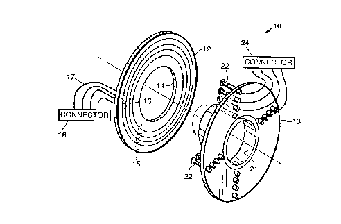
Fig. 1 illustrates an exploded perspective view of a spring loaded rotary
connector in accordance with the principles of the present invention; and

Fig. 2 illustrates a cross sectional side view of the spring loaded rotary
connector of Fig. 1.
DESCRIPTION OF THE PREFERRED EMBODIMENTS
Referring to the drawing figures, Fig. 1 illustrates an exploded perspective
view of a spring-loaded rotary connector 10 in accordance with the principles
of the
present invention. Fig. 2 illustrates a cross sectional side view of the
spring-loaded
rotary connector 10 of Fig. 1. The spring-loaded rotary connector 10 is
illustrated
with reference to its use in a shaft-type application, wherein its rotatable
components
are designed to mate with a shaft 11 that rotates relative to a fixed housing
25 or
member 25 or relative to the second member 13. However, it is to be understood
that
the present connector 10 may be readily used in other applications.
The exemplary rotary connector 10 is comprised of first and second members
12, 13 that are mutually rotatable relative to each other. As shown in Fig. I,
the first
member 12 may be comprised of a copper laminated phenolic ring 12a having an
opening 14 therein for receiving the shaft 11, that is machined (grooved) to
form a
plurality of electrically isolated metallic rings 15. Each of the rings I S
are drilled or
otherwise formed so that each ring 15 has a hole 16 therethrough. The holes 16
are
plated through to permit soldering of insulated electzical wires 17 thereto.
The holes
16 have insulated wire soldered therein on one side thereof (distal from the
second
member 13) and the wires 17 are routed to a connector 18 that provides for
connection to an external electrical signal source or power source (not
shown), for
example.
The second member 13 may comprise a phenolic plate 13a or ring 13a which
may have an opening 21 therein for receiving the shaft 11, and that is
machined to
accept a plurality of sets of spring-loaded individual pogo-stick type
contacts 22
generally mounted at equally spaced locations so that they are positioned to
engage
the plurality of electrically isolated metallic rings 15 of the copper
laminated phenolic
ring 13a or first member 13. Insulated wires 23 are soldered between
respective
bottoms of the pogo-stick type contacts 22 and a connector 24 that may be
connected
to one or more sensors (not shown), for example.

2i s ~~~"~
The pogo-stick type contacts 22 are commercially available, for example, from
Test-X Fixture Products (Riverside, California), part number TX416S2 or
TX4I6S3.
The spring-loaded rotary connector 10 permits relative angular movement
between the shaft 1 I and the housing 25 that secures the second member 13.
The
spring-loaded rotary connector 10 also compensates for movement between the
first
and second members 12, 13 in terms of their separation distance. More
specifically, if
the respective planes of the first and second members 12, 13 are not parallel,
then the
pogo-stick type contacts 22 adjust for the differences in distance
therebetween. This
may be caused by vibration of a vehicle, for example, or relative movement
between
the components that are connected to the shaft 1 l and the housing 25 to which
the
second member 13 is secured. This might be the relative movement between an
axle
and a wheel of a vehicle, for example. The relative motion is compensated for
by the
spring-loaded individual pogo-stick type contacts 22 which operate to keep
electrical
contact with the respective metallic rings I 5 irrespective of the relative
angular
relationship between the first and second members 12, 13.
The rotary connector 10 is shown as comprising flat members 12, 13 that are
designed to engage the shaft 11. However, it is to be understood that
contoured
members 12, 13 such as may be provided by cylindrical or spherical members,
for
example, may be employed as well as fiat members 12, 13. Therefore, the
present
connector 10 is not limited to a configuration that is flat.
The rotary connector 10 has been designed to withstand harsh outdoor
environments such as when it is used in axles of automobiles and trucks, for
example.
The rotary connector 10 may be used to transmit power or signals from a
stationary
object to a moving object. The rotary connector 10 has been developed to
replace
existing slip-ring type connectors currently used in many aircraft and vehicle
applications. The spring loaded rotary connector 10 is very rugged and
performs well
in harsh outdoor environments. Two connectors I O have been built and tested
on an
auto axle, and have performed well. The present invention may be used in cars
trucks
motor homes, motorcycles, and aircraft, wherever rotary electrical connectors
may be
employed.

Thus, an improved spring-loaded rotary connector has been described. It is to
be understood that the above-described embodiment is merely illustrative of
some of
the many specific embodiments which represent applications of the principles
of the
present invention. Clearly, numerous and other arrangements can be readily
devised
by those skilled in the art without departing from the scope of the invention.

Dessin représentatif
Une figure unique qui représente un dessin illustrant l'invention.
États administratifs

2024-08-01 : Dans le cadre de la transition vers les Brevets de nouvelle génération (BNG), la base de données sur les brevets canadiens (BDBC) contient désormais un Historique d'événement plus détaillé, qui reproduit le Journal des événements de notre nouvelle solution interne.

Veuillez noter que les événements débutant par « Inactive : » se réfèrent à des événements qui ne sont plus utilisés dans notre nouvelle solution interne.

Pour une meilleure compréhension de l'état de la demande ou brevet qui figure sur cette page, la rubrique Mise en garde , et les descriptions de Brevet , Historique d'événement , Taxes périodiques et Historique des paiements devraient être consultées.

Historique d'événement

Description Date
Le délai pour l'annulation est expiré 2007-05-08
Lettre envoyée 2006-05-08
Inactive : CIB de MCD 2006-03-12
Accordé par délivrance 2000-04-11
Inactive : Page couverture publiée 2000-04-10
Préoctroi 2000-01-17
Inactive : Taxe finale reçue 2000-01-17
Lettre envoyée 1999-12-16
Exigences de modification après acceptation - jugée conforme 1999-12-16
Inactive : Taxe de modif. après accept. traitée 1999-11-10
Modification après acceptation reçue 1999-11-10
Un avis d'acceptation est envoyé 1999-07-26
Lettre envoyée 1999-07-26
Un avis d'acceptation est envoyé 1999-07-26
Inactive : Approuvée aux fins d'acceptation (AFA) 1999-06-23
Inactive : Renseign. sur l'état - Complets dès date d'ent. journ. 1998-04-20
Inactive : Dem. traitée sur TS dès date d'ent. journal 1998-04-20
Demande publiée (accessible au public) 1996-11-23
Exigences pour une requête d'examen - jugée conforme 1996-05-08
Toutes les exigences pour l'examen - jugée conforme 1996-05-08

Historique d'abandonnement

Il n'y a pas d'historique d'abandonnement

Taxes périodiques

Le dernier paiement a été reçu le 1999-04-29

Avis : Si le paiement en totalité n'a pas été reçu au plus tard à la date indiquée, une taxe supplémentaire peut être imposée, soit une des taxes suivantes :

  • taxe de rétablissement ;
  • taxe pour paiement en souffrance ; ou
  • taxe additionnelle pour le renversement d'une péremption réputée.

Les taxes sur les brevets sont ajustées au 1er janvier de chaque année. Les montants ci-dessus sont les montants actuels s'ils sont reçus au plus tard le 31 décembre de l'année en cours.
Veuillez vous référer à la page web des taxes sur les brevets de l'OPIC pour voir tous les montants actuels des taxes.

Historique des taxes

Type de taxes Anniversaire Échéance Date payée
Enregistrement d'un document 1996-05-08
Requête d'examen - générale 1996-05-08
TM (demande, 2e anniv.) - générale 02 1998-05-08 1998-04-20
Enregistrement d'un document 1998-09-09
TM (demande, 3e anniv.) - générale 03 1999-05-10 1999-04-29
1999-11-10
Taxe finale - générale 2000-01-17
TM (brevet, 4e anniv.) - générale 2000-05-08 2000-04-25
TM (brevet, 5e anniv.) - générale 2001-05-08 2001-04-17
TM (brevet, 6e anniv.) - générale 2002-05-08 2002-04-16
TM (brevet, 7e anniv.) - générale 2003-05-08 2003-04-16
TM (brevet, 8e anniv.) - générale 2004-05-10 2004-04-13
TM (brevet, 9e anniv.) - générale 2005-05-09 2005-04-13
Titulaires au dossier

Les titulaires actuels et antérieures au dossier sont affichés en ordre alphabétique.

Titulaires actuels au dossier
HE HOLDINGS, INC. D/B/A HUGHES ELECTRONICS
RAYTHEON COMPANY
Titulaires antérieures au dossier
MOHI SOBHANI
Les propriétaires antérieurs qui ne figurent pas dans la liste des « Propriétaires au dossier » apparaîtront dans d'autres documents au dossier.
Documents

Pour visionner les fichiers sélectionnés, entrer le code reCAPTCHA :


Pour visualiser une image, cliquer sur un lien dans la colonne description du document. Pour télécharger l'image (les images), cliquer l'une ou plusieurs cases à cocher dans la première colonne et ensuite cliquer sur le bouton "Télécharger sélection en format PDF (archive Zip)" ou le bouton "Télécharger sélection (en un fichier PDF fusionné)".

Liste des documents de brevet publiés et non publiés sur la BDBC .

Si vous avez des difficultés à accéder au contenu, veuillez communiquer avec le Centre de services à la clientèle au 1-866-997-1936, ou envoyer un courriel au Centre de service à la clientèle de l'OPIC.


Description du
Document 
Date
(aaaa-mm-jj) 
Nombre de pages   Taille de l'image (Ko) 
Abrégé 1996-08-15 1 13
Description 1996-08-15 5 180
Revendications 1996-08-15 2 46
Dessins 1996-08-15 1 26
Dessin représentatif 1998-08-18 1 15
Dessin représentatif 2000-03-01 1 13
Description 1999-11-09 6 209
Revendications 1999-11-09 2 45
Rappel de taxe de maintien due 1998-01-20 1 111
Courtoisie - Certificat d'enregistrement (document(s) connexe(s)) 1998-07-02 1 140
Avis du commissaire - Demande jugée acceptable 1999-07-25 1 163
Avis concernant la taxe de maintien 2006-07-03 1 172
Correspondance 2000-01-16 1 49
Correspondance 1999-12-15 1 6