Language selection

Search

Patent 2176158 Summary

Third-party information liability

Some of the information on this Web page has been provided by external sources. The Government of Canada is not responsible for the accuracy, reliability or currency of the information supplied by external sources. Users wishing to rely upon this information should consult directly with the source of the information. Content provided by external sources is not subject to official languages, privacy and accessibility requirements.

Claims and Abstract availability

Any discrepancies in the text and image of the Claims and Abstract are due to differing posting times. Text of the Claims and Abstract are posted:

  • At the time the application is open to public inspection;
  • At the time of issue of the patent (grant).
(12) Patent: (11) CA 2176158
(54) English Title: GAS SENSING SYSTEM
(54) French Title: DISPOSITIF DE DETECTION DE GAZ DELETERES
Status: Term Expired - Post Grant Beyond Limit
Bibliographic Data
(51) International Patent Classification (IPC):
  • G01N 1/24 (2006.01)
  • G01M 3/16 (2006.01)
  • G01N 1/26 (2006.01)
(72) Inventors :
  • CULLEN, WILLIAM LEE (Canada)
(73) Owners :
  • WILLIAM LEE CULLEN
(71) Applicants :
  • WILLIAM LEE CULLEN (Canada)
(74) Agent: SANDER R. GELSINGGELSING, SANDER R.
(74) Associate agent:
(45) Issued: 2005-10-11
(22) Filed Date: 1996-05-09
(41) Open to Public Inspection: 1997-11-10
Examination requested: 2003-02-28
Availability of licence: N/A
Dedicated to the Public: N/A
(25) Language of filing: English

Patent Cooperation Treaty (PCT): No

(30) Application Priority Data: None

Abstracts

English Abstract

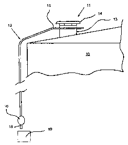
The invention relates to apparatus used for the detection of hazardous vapours or gases and includes a length of tubing, a first portion of the tubing provided with a number of spaced apart orifices, that first part of the tubing being located adjacent to or associated with a source of, for example, H2S gas. The tubing is connected to a pump which is associated with gas detection apparatus.


French Abstract

L'invention concerne un appareil servant à détecter les vapeurs ou gaz nocifs et qui comprend une longueur de conduite, une première partie de la conduite étant pourvue d'un certain nombre d'orifices espacés, ladite première partie de la conduite étant située adjacente à une source de gaz, par exemple du H2S, ou bien étant associée à cette source. La conduite est raccordée à une pompe qui est associée à l'appareil de détection de gaz.

Claims

Note: Claims are shown in the official language in which they were submitted.


THE EMBODIMENTS OF THE INVENTION IN WHICH AN EXCLUSIVE
PROPERTY OR PRIVILEGE IS CLAIMED ARE DEFINED AS FOLLOWS:
1. Leak detection apparatus comprising a length of tubing, having a first
section, a
second section and an internal diameter, each section being attached one to
the other by
connector means, said first section being provided with a number of spaced
apart orifices
having a combined diameter; said second section being provided, at its end
remote from
said first section with pump means, and wherein said pump means is associated
with
detector means and the combined diameter of said orifices do not exceeding
said internal
diameter.
2. The apparatus according to claim 1 wherein said first section is arranged
in a
circular configuration and is adapted to be held adjacent to and to surround a
hatch on an
oil tank from which toxic gas may leak.
3. The apparatus according to claim 1 wherein said pump means is an aspirator
bulb-
type pump.
4. The apparatus according to claim 1 wherein said detector means is a hand
held
H2S detector.
5. The apparatus according to claim 4 wherein said detector means is attached
to
said pump means.
-9-

6. The apparatus according to claim 1 wherein said detector is held in close
proximity to an outlet of said pump and not connected thereto.
7. The apparatus according to claim 1 wherein said first section of said
tubing is
substantially straight, and adapted to be utilized within an enclosure and to
be attached to
a structural component of said enclosure.
8. The apparatus according to claim 7 wherein said structural component is the
floor
of said enclosure.
9. The apparatus according to claim 7 wherein said second section of said
tubing
extends through a wall of said enclosure and said pump is attached to said
second section
externally of said enclosure.
10. The apparatus according to claim 1 wherein said first section is
structurally
incorporated within a hatch on an oil tank from which toxic gas may leak.
11. The apparatus according to claims 3 wherein said aspirator bulb-type pump
further comprises an outlet and wherein said outlet is associated with the
detector means.
-10-

Description

Note: Descriptions are shown in the official language in which they were submitted.


2176158
The invention relates in general to the detection of
hazardous vapours or gases, and more particularly
relates to apparatus to detect leakage of such vapours,
for example, hydrogen sulfide gas (H2S) from tanks in a
oil battery, or in buildings or enclosures which are
associated with a sour gas well and related equipment.
As is known, oil battery tanks are normally
pressurized to enable poisonous hydrogen sulfide gas to
be removed and piped from each tank to a location where
the gas is burned off, in, for example, a flare stack.
These tanks, are equipped with hatches, generally on the
roof which have built-in pressure relief valves, the
purpose of which is to relieve excess pressure within
the tank under emergency conditions, or provide a means
by which the contents of the tank may be sampled.
Should the seals or gaskets of these valves
breakdown, leakage of poisonous H2S gas may occur,
which, in the immediate vicinity of the tank can be
extremely dangerous to workers, but also, excess
quantities of such gases entering the atmosphere can be
environmentally unacceptable.
These hatches must therefore be inspected on a
regular basis and generally, to effect Such an
inspection, an operator would have to don a self-
contained breathing apparatus, ascend the tank and with
- 2 -

2116158
a portable H2S detector manually check for leaks around
each hatch cover. A second operative, is generally
situation on the ground, and who will continuously
monitor the operator on the tank, keeping a check on the
operator's air supply and ensuring that no malfunctions
in equipment can result in the operator being subject to
be overcome by poisonous gases.
Also, it is common in the oil industry to enclosure
a sour gas well or equipment for use on such well in a
building or enclosure. In such situations it is
important that the air in the building be monitored,
since operators have to enter these buildings on a
regular basis to do maintenance on equipment or take
instrumental readings. Since such buildings may be
isolated and in many cases have no permanent electrical
supply, the conventional electronic H2S detectors are
not usable. Operators therefore have to depend on their
personal hand-held H2S detectors to let them know if it
is safe to enter the building. Normally, while holding
his or her breath, the operator opens the door, enters
the monitor into the building and if it appears Safe to
do so, enters his or herself. Obviously, the danger of
the operator being overcome by gas while determining
whether it is safe to enter the building, is a very real
problem.
- 3 -

2176158
C.:
Notwithstanding the fact that this problem of H2S
detection has been around for many years, no
satisfactory solution has been forthcoming, to ensure
the safety of operators.
It is therefore an object of the invention to
provide a simple apparatus for detecting the presence of
hazardous or noxious vapours such as H2S, from a
location remote from the source of potential leakage,
without placing the operator in a dangerous situation.
Accordingly the invention comprises in a length of
tubing, a first section of which tubing is adapted to be
located adjacent an area of potential leakage, this
section is provided with plurality of spaced apart
orifices. A second section of tubing attached to said
first section by connection means, extends to a position
remote from said first section wherein it is connected
to a pump. The pump is associated with and/or used in
conjunction with a conventional H2S detector.
The invention will now be described by way of
example only, reference being had to the accompanying
drawings in which:
Figure 1 is a side view of an oil tank provided with
a hatch, an apparatus of the present invention installed
in proximity thereto;
Figure 2 is a perspective view of the apparatus
- 4 -

2116158
according to the invention of Figure 1;
Figure 3 is a perspective view of a second
embodiment of the present invention, as to be used
within an enclosed space.
Referring specifically to the drawings, Figure 1
shows schematically a conventional tank 10 which
contains sour gas (H2S), and/or oil. These type of
tanks are well known in the oil industry and therefore
no detailed description is provided herewith.
On the roof of the tank is shown a hatch 11, again
these hatches are conventional, a particular type of
hatch may be referred to as a "thief hatch" manufactured
by Enardo Manufacturing Company of Tulsa, Oklahoma
U.S.A. under model number 660.
These hatches are used on both low pressure steel
and fibreglass tanks, and include a pressure relief
valve arranged such that it can be actuated in emergency
situations to relieve pressure, and also these valves
are designed to enable operators to sample or gauge the
contents of the tank.
Bearing in mind that the fact that no mechanical
device is foolproof, these hatches and their attendant
valves are susceptible to leakage, and it is a
regulatory requirement that inspections be carried out
in view of the obvious danger should toxic gases be
- 5 -

217b158
related to atmosphere.
The general procedure carried out to inspect these
hatches has been described above, and, the basis of the
present invention is to provide apparatus that can be
used by an operator, from the ground, safely, which
apparatus can also be used in connection with enclosures
or buildings, as again previously mentioned, within
which a sour gas well and related equipment is
positioned, and could possibly be subjected to leakage.
The apparatus as used in the arrangement according
to Figure 1 is shown more specifically in Figure 2, and
comprises a tube 12, which may be looped around the
hatch base 13 adjacent to the cover 14. The looped
tubing 12 is connected to a T-connection 15
(conventional) from which it extends to the ground where
it is attached to an air pump 16, in this case being a
rubber aspirator bulb 17. The outlet 18 of the bulb is
attached to or held close to a conventional hand held
H2S detector 19.
Referring back to the looped portion of tube 12,
that portion is provided with a number or orifices 20
located in spaced-apart relation around the loop. The
size and number of orifices 20 is not critical except
that the combined diameters of orifices 20 must not
exceed the internal diameter of the tube 12.
- 6 -

2116158
(:
In operation, the aspirator bulb 17 is squeezed by
the operator to cause the air to be drawn around the
hatch 11, through the orifices 20 to the ground where it
(the air> is sensed by the detector 19. If H2S gas is
present the monitor will send an alarm and the operator
will be able to don the necessary protective equipment
and clothing to proceed to effect such repair as is
necessary to the hatch and related valve assembly.
Since only one operator is necessary not only time is
saved but considerable expense. Also, as will be
appreciated the safety factor is also much increased.
A second embodiment of the invention is shown in
Figure 3. The basic apparatus is the same as described
above, the difference being that this arrangement is for
use in sensing the presence of toxic vapours within an
enclosed space or building.
Operators or workers, must enter these buildings on
a daily basis to check equipment or take instrumental
readings. They obviously cannot be certain that it is
safe to do so.
The structure according to Figure 3 therefore
comprises a length of tubing 12 which is located within
the building, for example, on the floor or attached to
an internal wall. That section indicated at 21 is
provided as per the first embodiment with orifices 20.

2176158
The tube 12, is then passed through the external
wall (not shown) of the enclosure and is as previously
described, attached to an aspirator bulb 17.
The operation of this arrangement is as previously
described, if no toxic gas is detected, the operator can
safely enter the building or enclosure.
If gas is detected, then the operator as before can
don such protective equipment as is necessary to effect
repair.
It will be appreciated that various modifications
may be made to the invention as heretofore described,
without departing from the scope of the claims as
appended hereto.For example, in connection with the
first embodiment, the tube 12 shown looped around the
hatch base 13 could be incorporated within the confines
of the hatch as a permanent structure.
Furthermore, while the in the first embodiment has
been described in connection with a single tank, it will
be appreciated that in a battery of tanks, air from the
vicinity of each hatch could be piped to a single
monitor thorugh an automatic switching manifold and a
continuously running air pump, thus providing continuous
readouts.
_ g _

Representative Drawing
A single figure which represents the drawing illustrating the invention.
Administrative Status

2024-08-01:As part of the Next Generation Patents (NGP) transition, the Canadian Patents Database (CPD) now contains a more detailed Event History, which replicates the Event Log of our new back-office solution.

Please note that "Inactive:" events refers to events no longer in use in our new back-office solution.

For a clearer understanding of the status of the application/patent presented on this page, the site Disclaimer , as well as the definitions for Patent , Event History , Maintenance Fee  and Payment History  should be consulted.

Event History

Description Date
Inactive: Expired (new Act pat) 2016-05-09
Small Entity Declaration Request Received 2008-04-24
Small Entity Declaration Determined Compliant 2008-04-24
Grant by Issuance 2005-10-11
Inactive: Cover page published 2005-10-10
Pre-grant 2005-08-02
Inactive: Final fee received 2005-08-02
Notice of Allowance is Issued 2005-07-08
Letter Sent 2005-07-08
Notice of Allowance is Issued 2005-07-08
Inactive: Approved for allowance (AFA) 2005-06-30
Revocation of Agent Requirements Determined Compliant 2005-05-17
Inactive: Office letter 2005-05-17
Appointment of Agent Requirements Determined Compliant 2005-05-17
Amendment Received - Voluntary Amendment 2005-05-10
Revocation of Agent Request 2005-05-06
Appointment of Agent Request 2005-05-06
Inactive: S.30(2) Rules - Examiner requisition 2005-03-01
Letter Sent 2004-12-23
Inactive: Office letter 2004-11-10
Inactive: Applicant deleted 2004-11-10
Appointment of Agent Requirements Determined Compliant 2004-11-10
Revocation of Agent Requirements Determined Compliant 2004-11-10
Inactive: Office letter 2004-11-10
Reinstatement Request Received 2004-11-05
Reinstatement Requirements Deemed Compliant for All Abandonment Reasons 2004-11-05
Amendment Received - Voluntary Amendment 2004-11-05
Revocation of Agent Request 2004-11-05
Appointment of Agent Request 2004-11-05
Inactive: Abandoned - No reply to s.30(2) Rules requisition 2003-11-05
Inactive: S.30(2) Rules - Examiner requisition 2003-05-05
Inactive: Status info is complete as of Log entry date 2003-03-24
Letter Sent 2003-03-24
Letter sent 2003-03-24
Advanced Examination Determined Compliant - paragraph 84(1)(a) of the Patent Rules 2003-03-24
Inactive: Application prosecuted on TS as of Log entry date 2003-03-24
Inactive: Advanced examination (SO) fee processed 2003-02-28
Request for Examination Requirements Determined Compliant 2003-02-28
All Requirements for Examination Determined Compliant 2003-02-28
Inactive: Delete abandonment 1999-06-10
Deemed Abandoned - Failure to Respond to Maintenance Fee Notice 1999-05-10
Inactive: Inventor deleted 1998-04-14
Application Published (Open to Public Inspection) 1997-11-10

Abandonment History

Abandonment Date Reason Reinstatement Date
2004-11-05
1999-05-10

Maintenance Fee

The last payment was received on 2005-05-06

Note : If the full payment has not been received on or before the date indicated, a further fee may be required which may be one of the following

  • the reinstatement fee;
  • the late payment fee; or
  • additional fee to reverse deemed expiry.

Please refer to the CIPO Patent Fees web page to see all current fee amounts.

Fee History

Fee Type Anniversary Year Due Date Paid Date
MF (application, 2nd anniv.) - small 02 1998-05-11 1998-03-30
MF (application, 3rd anniv.) - small 03 1999-05-10 1999-05-10
MF (application, 4th anniv.) - small 04 2000-05-09 2000-03-13
MF (application, 5th anniv.) - small 05 2001-05-09 2001-03-05
MF (application, 6th anniv.) - small 06 2002-05-09 2002-03-18
MF (application, 7th anniv.) - small 07 2003-05-09 2003-02-28
Request for examination - small 2003-02-28
Advanced Examination 2003-02-28
MF (application, 8th anniv.) - small 08 2004-05-10 2004-03-19
Reinstatement 2004-11-05
MF (application, 9th anniv.) - small 09 2005-05-09 2005-05-06
Final fee - small 2005-08-02
MF (patent, 10th anniv.) - small 2006-05-09 2006-04-03
MF (patent, 11th anniv.) - small 2007-05-09 2007-05-07
MF (patent, 12th anniv.) - small 2008-05-09 2008-04-24
MF (patent, 13th anniv.) - small 2009-05-11 2009-04-20
MF (patent, 17th anniv.) - small 2013-05-09 2010-05-10
MF (patent, 14th anniv.) - small 2010-05-10 2010-05-10
MF (patent, 16th anniv.) - small 2012-05-09 2010-05-10
MF (patent, 15th anniv.) - small 2011-05-09 2010-05-10
MF (patent, 19th anniv.) - small 2015-05-11 2010-05-10
MF (patent, 18th anniv.) - small 2014-05-09 2010-05-10
Owners on Record

Note: Records showing the ownership history in alphabetical order.

Current Owners on Record
WILLIAM LEE CULLEN
Past Owners on Record
None
Past Owners that do not appear in the "Owners on Record" listing will appear in other documentation within the application.
Documents

To view selected files, please enter reCAPTCHA code :


To view images, click a link in the Document Description column. To download the documents, select one or more checkboxes in the first column and then click the "Download Selected in PDF format (Zip Archive)" or the "Download Selected as Single PDF" button.

List of published and non-published patent-specific documents on the CPD .

If you have any difficulty accessing content, you can call the Client Service Centre at 1-866-997-1936 or send them an e-mail at CIPO Client Service Centre.


Document
Description 
Date
(yyyy-mm-dd) 
Number of pages   Size of Image (KB) 
Representative drawing 1997-11-13 1 4
Cover Page 1997-11-13 1 31
Cover Page 1998-08-24 1 31
Cover Page 1996-08-19 1 14
Abstract 1996-08-19 1 11
Description 1996-08-19 7 223
Claims 1996-08-19 2 49
Drawings 1996-08-19 3 41
Claims 2004-11-05 4 83
Drawings 2004-11-05 3 22
Claims 2005-05-10 2 50
Representative drawing 2005-06-30 1 4
Cover Page 2005-09-15 1 27
Notice: Maintenance Fee Reminder 1998-02-10 1 120
Notice: Maintenance Fee Reminder 1999-02-10 1 118
Notice: Maintenance Fee Reminder 2000-02-10 1 121
Notice: Maintenance Fee Reminder 2001-02-12 1 120
Notice: Maintenance Fee Reminder 2002-02-12 1 119
Reminder - Request for Examination 2003-01-13 1 112
Notice: Maintenance Fee Reminder 2003-02-11 1 115
Acknowledgement of Request for Examination 2003-03-24 1 185
Notice: Maintenance Fee Reminder 2004-02-10 1 116
Courtesy - Abandonment Letter (R30(2)) 2004-01-14 1 168
Notice of Reinstatement 2004-12-23 1 170
Commissioner's Notice - Application Found Allowable 2005-07-08 1 160
Fees 2003-02-28 3 104
Correspondence 2003-03-24 1 10
Correspondence 1997-01-09 3 63
Fees 2002-03-18 1 80
Fees 1998-03-30 2 130
Fees 2000-03-13 2 89
Fees 1999-05-10 2 72
Fees 2001-03-05 1 45
Fees 2004-03-19 1 64
Correspondence 2004-11-05 2 50
Correspondence 2004-11-10 1 15
Correspondence 2004-11-10 1 20
Fees 2005-05-06 2 222
Correspondence 2005-05-06 4 283
Correspondence 2005-05-17 1 14
Correspondence 2005-05-17 1 17
Correspondence 2005-08-02 1 41
Fees 2006-04-03 1 39
Fees 2007-05-07 2 45
Correspondence 2008-04-24 2 56
Fees 2008-04-24 2 56
Fees 2009-04-20 1 42
Fees 2010-05-10 1 48