Note: Descriptions are shown in the official language in which they were submitted.
2176426
1
Our Reference: AHAN4361 (ITT-267-A) PATENT
SEAT TRACR APPARATUS
FIELD OF THE INVENTION
The present invention relates to a seat track apparatus for a
vehicle, and in particular, to a seat track apparatus that maintains the
position of a slide member between a lower seat track and an upper seat
track of a seat track assembly of a motor vehicle.
BACKGROUND OF THE INVENTION
Seat adjusters, both manual and powered, are provided on most
automotive vehicles. One of the most common seat adjustments is fore
and aft movement of the seat with respect to the vehicle. To provide
such fore and aft seat adjustment, the seat assembly is typically
mounted on first and second spaced seat track assemblies. Each seat
track assembly is formed by a lower seat track anchored to the vehicle
floor, and an upper seat track connected to an upper support frame or
bottom of a seat assembly wherein the upper seat track is slidably
mounted to the lower seat track. To allow the upper seat track to slide
with respect to the lower seat track and provide the fore and aft seat
adjustment, a bearing or low-friction sliding surface is commonly
provided between the metallic surfaces of the upper and lower seat
tracks.
Plastic members called "slides" are commonly utilized as low-
friction surfaces to reduce the friction between the upper and lower
seat tracks of the seat track assembly and provide the fore and aft
adjustment of the upper seat track with respect to the lower seat track.
Typically, the slides have a shape complementary to both the lower seat
track and the upper seat track so as to mate and complement the
configuration between the upper and lower seat tracks.
Besides the complementary shape of the slides, the slides are
often tenuously held in place within the seat track assembly by a type
of retaining feature. One known retaining feature provides cylindrical
pins which extend outwardly from the slides and are inserted through
corresponding apertures within the side wall of the lower seat track of
2176426
2
the seat track assembly. Thus, the cylindrical pins prohibit movement
in a plane normal to the longitudinal axis of the pins which includes
fore and aft movement of the slide with respect to the lower seat track
of the seat track assembly. Linear movement along the longitudinal axis
of the cylindrical pins of the slide is generally restrained by the
complementary structure of the slide and the upper seat track of the
seat track assembly. ,
It would be desirable to provide a seat track apparatus that
retains the slide within the seat track assembly during all phases of
the assembly process as well as during all modes of operation. It would
also be desirable to provide a seat track apparatus that retains the
slide and is inexpensive, does not require additional parts, and does
not considerably increase assembly time.
SUMMARY OF THE INVENTION
The present invention provides a seat track apparatus that
retains a slide member within the seat track assembly of a vehicle. The
seat track apparatus provides a channel defining means having at least
one longitudinally extending contact surface. A low-friction slide
member, having a shape complementary to the channel means, is disposed
within the channel defining means and has at least one contact surface
in contact with the contact surface of the channel defining means. A
self-locking means for maintaining contact between the contact surface
of the slide member and the contact surface of the channel defining
means is provided to retain the slide member within the seat track
assembly.
In the preferred embodiment, the self-locking means for
maintaining contact between the contact surfaces of the slide member and
the channel defining means provides the slide member with at least one
projection extending from a bottom wall of the slide member. The
channel defining means also provides a bottom wall having at least one
aperture for receiving the projections of the slide member so as to
maintain contact between the contact surfaces of the slide member and
the channel defining means.
217642b
3
In an additional embodiment, the self-locking means for
maintaining contact between the contact surfaces of the slide member and
the channel defining means provides a bottom wall of the channel
def fining means with at least one raised portion adj acent the bottom wall
of the slide member so as to maintain contact between the contact
surfaces of the slide member and the contact surfaces of the channel
deffining means. Preferably,,the raised portions of the bottom wall of
the channel defining means are formed by punching lanced upsets into the
floor of the channel defining means so as to retain the slide member
within the seat track assembly.
The present invention also provides the slide member with at
least one cylindrical pin integral with and extending from the side wall
of the slide member. The channel defining means provides at least one
aperture within its side wall for receiving the cylindrical pin of the
slide member for aligning and retaining the slide member within a plane
normal to the longitudinal axis of the pin.
The present invention may be utilized with a plurality of
slide members wherein the slide members are longitudinally spaced along
the channel defining means. The present invention may also be utilized
to form a lower seat track having a pair of opposing channel defining
means with a plurality of slides longitudinally spaced and disposed
within said opposing channel defining means wherein a common bottom wall
is utilized to form an integral, unitary lower track.
To this end, the objects of the present invention are to
provide a new and improved seat track apparatus for maintaining the
position of a slide member within a seat track assembly without the use
of additional parts or additional assembly time.
BRIEF DESCRIPTION OF THE DRAWINGS
The various features, advantages and other uses of the present
invention will become more apparent by referring to the following
detailed description and drawings which:
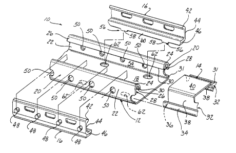
Figure 1 is an exploded view showing the lower seat track,
upper seat track and slide member of the seat track apparatus and
2176426
4
showing the preferred embodiment of the self-locking means for
maintaining the position of the slide member within the seat track
assembly.
Figure 2 is a sectional view showing the projections in the
bottom wall of the slide member extending into the apertures provided in
the bottom wall of the lower seat track for maintaining the position of
the slide member within the seat track assembly.
Figure 3 is a sectional view showing the lanced upsets in the
bottom wall of the lower seat track for maintaining the position of the
slide member within the seat track assembly.
Figure 4 is a sectional view of the prior art showing the
cylindrical pins extending from the side wall of the slide member and
extending through the corresponding apertures in the side wall of the
lower seat track.
DESCRIPTION OF THE PREFERRED EMBODIMENT
Figure 1 is an exploded view showing a seat track apparatus 10
for a vehicle (not shown). A lower seat track 12 is fixedly mounted to
a motor vehicle floor (not shown), and an upper seat track 14 is
connected to an upper vehicle support bracket (not shown) or directly to
the bottom of a vehicle seat (not shown). A low friction, plastic slide
member 16 is disposed between the upper seat track 14 and the lower seat
track 12 of the seat track apparatus 10 to provide low-friction fore and
aft sliding of the upper seat track 14 with respect to the lower seat
track 12.
As seen in Figures 1-4, the lower seat track 12 may be formed
of an integral, one piece member having a substantially planar bottom
wall 18 and a pair of similarly formed side walls 20 extending upwardly
from opposite sides of the bottom wall 18. Each of the_side walls 20
includes a vertically extending, outer planar side wall 22, a top wall
24 and an inwardly disposed lip or inner wall 26 which extends
substantially vertically downward from the top wall 24 and is spaced
from the outer side wall 22. The outer side wall 22, the top wall 24
and the inner wall 26 are formed in an inverted J-shape defining a
z ~ ~6~z~
longitudinally extending channel 28. A lower edge 30 of the inner wall
26 is spaced from the bottom wall 18 of the lower seat track 12 to form
an elongated slot 31.
At least one slide member 16 is disposed in each channel 28 of
5 the lower seat track 12 wherein a pair of the channels 28 are opposed
and joined by the bottom wall 18 to form the lower seat track 12. Each
slide member 16 is substantially C-shaped and is complementary to the
shape of the channel 28 in the lower seat track 12. The C-shape of the
slide member 16 is defined by a top wall 42, a side wall 44 and a bottom
wall 46. The slide member 16 is fabricated of a suitable plastic
material to provide a smooth sliding surface for the upper seat track 14
which is slidingly disposed within the slide member 16.
The upper seat track 14 provides side walls 32 that are formed
in a channel-like configuration complementary to the shape of the
channels 28 in the lower seat track 12 so as to enable the upper seat
track 14 to be slidably disposed within the lower seat track 12 in
sliding contact with the slide member 16. Thus, each side wall 32 of
the upper seat track 14 is formed with a substantially J-shaped
configuration formed of an outer side wall 34, a lower bottom wall 36
and an inner side wall 38 which extends to a central raised portion 40
of the upper seat track 14. The same channel-like configuration is also
provided for the opposite longitudinal side wall 32 of the upper seat
track 14.
In order to align and retain the position of the slide member
16 in a limited plane with respect to the lower seat track 12, the slide
member 16 provides a plurality of outwardly extending cylindrical pins
48 formed on and extending outwardly from the side wall 44 of the slide
member 16. The pins 48 are received by a plurality of apertures 50
formed in the outer side walls 22 of the lower seat track 12. The pins
48 engage and extend through the apertures 50 in the outer side walls 22
of the lower seat track 12 to align and position the slide member 16
within the lower seat track 12. When the pins 48 are extended through
the apertures 50 of the outer side wall 22 of the lower seat track 12,
~ ~ 7~4~~6
6
the slide member 16 is restrained from moving within the plane defined
by the outer side wall 22 of the lower seat track 12 or within a plane
normal to a longitudinal axis 52 of the pins 48. Thus, the side wall 44
of the slide member 16 provides a planar contact surface in contact with
a planar contact surface formed by the inner surface 54 of the outer
side wall 22 of the lower seat track 12. In addition, the bottom wall
46 of the slide member 16 forms a planar contact surface in contact with
a planar contact surface formed by the central bottom wall 18 of the
lower seat track 12.
To prevent the contact surfaces of the slide member 16 and the
lower seat track 12 from separating due to loads applied by the upper
seat track 14 or random forces and vibration from miscellaneous assembly
operations and material handling processes, a self-locking means for
maintaining contact between the aforementioned contact surfaces is
provided, as seen in Figure 2. In the preferred embodiment, a pair of
similar projections 56 are integral with and extend downwardly from the
bottom wall 46 of the slide member 16. Each projection 56 ramps
downwardly at an acute angle wherein an end face or shoulder 58 is
formed continuously with an end face 60 of the bottom wall 18 of the
slide member 16. The projections 56 extending from the bottom wall 46
of the slide member 16 are received by oval shaped apertures 62
extending through the bottom wall 18 of the lower seat track 12. The
projections 56 of the slide member 16 may only be deep enough to extend
through a portion of the aperture 62 so that the projections 56 do not
interfere with any mounting surfaces (not shown) that may lye beneath
the lower seat track 12. Thus, the projections 56 may abut any portion
of the lower seat track 12 def fining the apertures 62 to maintain the
position of the slide member 16 between the lower seat track 12 and the
upper seat track 14 of the seat track apparatus 10. The projections 56
of the slide member 16 within the apertures 62 of the lower seat track
12 in combination with the outwardly extending pins 48 of the slide
member 16 received by the apertures 56 of the outer side wall 22 of the
lower seat track 12 and the complementary shape of the top wall 42 of
217626
the slide member 16 disposed within the channel 28 of the lower seat
track 12 ensures that the slide member 16 is retained within the seat
track apparatus 10.
As seen in Figure 3 , a second embodiment provides self-locking
means for maintaining contact between contact surfaces of the slide
member 16 and the lower seat track 12 wherein a plurality of raised
portions 64 are provided on the bottom wall 18 of the lower seat track
12 adjacent the end face 60 of the bottom wall 46 of the slide member
16. The raised portions 64 of the bottom wall 18 of the lower seat
track 12 may be formed by punching lanced upsets into the bottom wall 18
of the lower seat track 12. The lanced upsets provide a cornered edge
66 for retaining the bottom wall 46 of the slide member 16 and
prohibiting the end face 60 of the bottom wall 46 of the slide member 16
from moving past the raised portion 64 of the bottom wall 18 of the
lower seat track 12 and away from the side wall 20 of the lower seat
track 12. Thus, the end face 60 of the bottom wall 46 of the slide
member 16 may abut the cornered edge 66 of the lanced upset of the
raised portion 64 of the bottom wall 18 of the lower seat track 12 in
order to retain the slide member 16 in the proper position within the
seat track apparatus 10.
In operation, the slide member 16 is inserted into the lower
seat track 12 of the seat track apparatus 10 by pivoting the top wall 42
of the slide member 16 into the upper portion of the channel 28 of the
lower seat track 12. The cylindrical pins 48 extending from the side
walls 44 of the slide member 16 are aligned with the apertures 50
provided in the outer side wall 22 of the lower seat track 12, and the
slide member 16 is continually pivoted so that the cylindrical pins 48
extend through the apertures 50 in the outer side walls 22 of the lower
seat track 12. In the preferred embodiment, the slide member 16 is
continually pivoted rearward until the projections 56 extending from the
bottom wall 46 of the slide member 16 engage the apertures 62 in the
bottom wall 18 of the lower seat track 12. The projections 56 on the
slide member 16 may provide a snap fit within the apertures 62 in the
2176426
8
bottom wall 18 of the lower seat track 12 such that the slide member 16
is snugly disposed within the lower seat track 12. The upper seat track
14 may then be slidingly inserted into the slide member 16 of the seat
track apparatus 10.
In the second embodiment, the top wall 42 of the slide member
16 is similarly pivoted into the upper portion of the channel 28 of the
lower seat track 12, and the,cylindrical pins 48 of the slide member 16
are aligned and inserted into the apertures 50 provided in the outer
side wall 22 of the lower seat track 12. To pivot the bottom wall 46 of
the slide member 16 over the lanced upsets 64 in the bottom wall 18 of
the lower seat track 12, an interference fit may be provided such that
the bottom wall 46 of the slide member 16 may deform slightly when
pivoting the bottom wall 46 of the slide member 16 over the lanced
upsets 64 in the bottom wall 18 of the lower seat track 12. Since the
slide member 16 may be fabricated from a plastic material, the slide
member 16 may bend under sufficient force when the slide member 16 is
pivoted over the lanced upsets 64, and the slide member 16 flexes back
to its original relaxed condition once the bottom wall 46 of the slide
member 16 has passed over the lanced upsets 64 in the bottom wall 18 of
the lower seat track 12. The upper seat track 14 may then be slidingly
inserted into the slide member 16 of the seat track apparatus 10.
While the invention has been described in connection with what
is presently considered to be the most practical and preferred
embodiment, it is to be understood that the invention is not to be
limited to the disclosed embodiments but, on the contrary, is intended
to cover various modifications and equivalent arrangements included
within the spirit and scope of the appended claims, which scope is to be
accorded the broadest interpretation so as to encompass all such
modifications and equivalent structures as is permitted under the law.