Note: Descriptions are shown in the official language in which they were submitted.
2~ 76497
.
I8665WO-NF/1s~1
"lM~Kuv~L~L, IN OR R~!T.~ _ TO A MOISTURE-SENSING
APPARAT'aS"
T~E P}cESENT lNV~l~LlUN relates to a moi2,Lu,-- __.,sing
apparatus and more particularly relates to à moisture-
sensing apparatus adapted to sense the moisture of a
flowable material, such as grzin, pulses or manufactured
material of a granular or " f lowable" nature . The sensor
may be used to sense the moisture content o~ almost any
granular, flowable material.
It has been proposed previously to provide a
moisture-sensing apparatus for sensing the moisture content
of a material such zs grain, the apparatus comprising ~n
elongate spear having, at one end, a reading "head". The
spear may be plunged into a pile of grain or the like so
that the "head" is fully embedded within the grain. The
moisture content of the grain is measured using variations
in temperature compensated electric f ield strength . An
~mh~ 0~ this particular type of moisture-sensor which
is suitable for use with agricultural grains such as wheat,
barley, oats, etc., is described in full in British Patent
Specif ication No . 2, 222, 683A.
An article entitled "Valuation Sensors of
Agricultural Products" published in "Sensors and
Actuators B Chemical", B16 (1/3 o~ October 1993)
(pages 275-278) discloses a moisture-sensing apparatus, for
sensing the moisture content of a flowable material, such
as grain. The apparatus comprises a moisture-sensing
arrangement, which is contained within a housing. The
housing has, at its upper end, an inlet for the flowable
material and the housing has, at its lower end, means
AMENDE~ SHEFI`
2 1 7~97
-lA-
defining an outward flow path for material within the
housing. In the illustrated arrangement, the housing is
provided with deflector plates at the upper end to prevent
the direct downward flow of material into the housing, and
is provided with a shutter at the lower end, to control the
rate of flow of material from the housing.
GB-A-360,544 discloses a similar moisture-sensing
apparatus, with- a ~housing containing a molaLu.. e_..sing
element. Horizontally slidable shutters are provided at
the top and at the bottom of the housing to control the
flow of material through the housing.
Database WPI, week 8303 (Derwent Publications
Limited, London GB) AN83-89576~C ~03) of 2nd March 1983
comprises an abstract relating to a moi~uL. ~u~ent sensor
for use with bulk materials. A measuring chamber has a
central spigot which co-operates with the body wall of the
measuring chamber to form a capacitative sensor. An upper
shutter is provided to control the flow of material into
the ohamber.
This particular sensor operates well with a pile of
grain or the like, but is not practicable for use when the
moisture content of a f low of grain or the like is to be
determined .
There are many situations when it is desirable to
be able to ~ t~rmin~ the moisture content of a flow of
grain or the like.
For example, when agricultural grain is being
harvested using a combine harvester, it is desirable to be
able to determine the moisture content of the grain as it
is harvested. There are two reasons for this. Firstly, in
many cases a farmer is anxious to know the moisture content
of the grùin, so as to be able to determine whether it is
A~ ENDE~ SHEET
21 76497
.
-1B- ==
economic to harvest the grain. If grain is harvested which
is very moist, it is necessary to dry the grain after
harvesting before the grain can be stored or sold. This
drying ~ eduL 2 is time consuming and expensive. A farmer
may, therefore, prefer not to harvest grain when the
moisture content is too high, but instead may choose to
leave the grain standing in the f ield until the sun has
dried the grain to a lower moisture content Secondly, it
is to be noted that many combine harvesters have a "yield
per acre" meter which dc~tDrm~nDc the quantity of grain
being harvested as the combine harvester advances through
the crop, providing an instantaneous read-out as to the
~uantity of grain measured on a "tonnes per hectare" basis.
The combine harvester can, of course, only measure the
weight of the grain and if the grain has a high moisture
content, then the grain "weighs heavy" and may ~ive an
over-optimistic reading in terms of tonnes per hectare.
Alternatively, if the grain has a very low moisture content
it will "weigh light" and may give a pessimistic reading in
tonnes per hectare. However, if it were possible to
r~DtDrm;nD substantially instantaneously the moisture
content of the grain, then the reading provided could be
corrected for the moisture content, and could provide a
"tonnes per hectare" reading corrected to a predetermined
moisture level .
AMENDED SHEET
W095114228 2 1 ~ ~ ~ 9 7 ~
--2--
There are many situations when it is desirable to
be able to determine the moisture content of a flow of
grain or the like.
For eYample, when agricultural grain is being
harvested using a combine harvester, it i8 ~ c;ri~hl~ to be
able to ~at~rminp the moisture content of the grain as it
is hdLv- sLed. There are two reasons for this. Firstly, in
many cases a farmer is anYious to know the moisture content
of the grain, 80 as to be able to determine whether it is
e~-- ic to harvest the grain. If grain is harvested which
is very moist, it is n~r~cc:~ry to dry the grain after
harvesting before the grain can be stored or sold. This
drying ~o~ u~ is time rnnc~-ning and expensive. A farmer
may, therefore, prefer not to harvest grain when the
moisture content is too high, but instead may choose to
leave the grain standing in the f ield until the sun has
dried the grain to a lower moisture content. Secondly, it
is to be noted that many combine harvesters have a "yield
per acre" meter which ~ot~rm; n~c the quantity of grain
being harvested as the combine harvester advances through
the crop, providing an instantaneous read-out as to the
guantity of grain measured on a "tonnes per hectare" basis.
The combine harvester can, of course, only measure the
weight of the grain and if the grain has a high moisture
content, then the grain "weighs heavy" and may give an
ov~L-~,yLimistic reading in terms of tonnes per hectare.
Alternatively, if the grain has a very low moisture content
it will "weigh light" and may give a pessimistic reading in
tonnes per hectare. However, if it were pocsihle to
detPrmin~ substantially instant~ o~Cly the moisture
content of the grain, then the reading provided could be
corrected for the moisture content, and could provide a
"tonnes per hectare" reading corrected to a predetermined
moisture ievel.
WO 9~114228 2 ~ 7 ~ 4 9 i7 ~ c~;
--3--
It is envisaged that further situations may well
exist where it i8 desirable to be able to measure
substantially instantaneously the moisture content of a
flow of grain. For example, in a re-circulating
agricultural grain dryer moist grain is circulated
cont- i n~ A l y through a drying chamber . In order to
t~min~ the moisture content of grain within a dryer it
is presently n~c~Cc::~ry to withdraw a sample of grain for
moisture mea:,u. L. I~ it were possible, however, to
measure the moisture of the grain which is recycling within
the dryer substantially instantaneously, the dryer could be
operated until a predetermined moisture level is detected,
and then the dryer could be automatically stopped, or an
d~JL U~L iate indicator could be activated .
There are many other potential applications for a
device which can measure the moisture content of a stream
of material. For example, reference may be made to food
products such as rice, pasta, processed cereal ~?L ~ L:.,
animal feed, dried vegetables and the like.
It has been f ound that whilst the spear of British
Patent sp~ if ication No. 2,222,683A operates satiAf~ct~rily
when plunged into a pile of agricultural grain, a spear of
this type does not operate in a reliable manner when
inserted into a stream of f lowing material . The spear
requires substantially stationary material adjacent the
operative parts of the spear in order to provide a reliable
reading. It has been found also that if such a spear is
located with the operative part of the spear in the lower
region of the grain-storing hopper present on a combine
harvester, the reading that is provided is again erratic
since, as the quantity of grain within the hopper
increases, the packing density of the grain adjacent the
operative part of the spear increases due to the increased
; ', ' ! ' ' .,, ' ' ! ,. i ' ~ . - ,',
~.. . .
97
--4--
pressure within the grain. Thus a f luctuating reading is
provided, the fluctuations being dependent upon the
quantity of grain within the grain storage hopper.
The present invention seeks to provide an improved
moisture-sensing apparatus.
. . _ , . . . _ , _ _ _ _ _
According to one aspect of this invention there is
provided a moisture-sensing apparatus, for sensing the
moisture content of a granular flowable material, the
apparatus comprising a moi,,LuL, s=l.sing element, a housing
containing the moisture-sensing element, the housing
having, at its upper end, an inlet for flowable material,
the housing having, at its lower end, means de~ining an
outward f low path for material within the housing, the
housing forming part of a means to control the packing
density of said flowable material within the housing,
wherein the said means to control packing density comprise
an upper element provided with means which prevent material
from flowing verticAlly downwardly into the housing and
which define one or more apertures, each aperture lying in
a substantially vertlcal plane to permit material to flow
into the housing.
Conveniently the means to control packing density
additionally comprise an open topped funnel to direct a
f low of said f lowable material to said inlet .
According to another aspect of this invention there
is provided a moisture-sensing apparatus, for sensing the
moisture content of a granular flowable material the
apparatus comprising A moisture-sensing element, a housing
containing a moisture-sensing element, the housing having,
at its upper end, an inlet for flowable material associated
with an upper element provided with means which prevent
mAterial
AMEND~D SHEET
W095/14228 ~ 97 P~ A?~C
from flowing vertically downwardly into the housing and
which def ine one or more ~Ipe~ Lu, as, each aperture lying in
a substantially vertical plane to permit material to f low
into the housing, the housing having, at its lower end,
means r3~f;ning an outward flow path for material within the
housing .
Advantageously the upper element of the housing
comprises means defining a horizontal upper wall and a
ron~l; n~ side wall, there being one or more of said
apertures in the side wall.
Conveniently each aperture is of elongate oval
f orm .
Preferably each a.E~ L Lu~;' extendfi substantially
horizontally peripherally around said side wall.
In an alternative ~mho~ i L to the invention the
upper element of the housing comprises a plurality of
baffles, an upper baffle being provided adapted to
substantially overlap a lower baffle.
Conveniently each baffle comprises a substantially
planar plate ;n~ linPd at a pr~ t~rmin~d angle to the
horizontal angle, the said aperture being defined between
the overlapping regions of the two baffles.
Preferably sensor means are provided adapted to
sense when the housing is full of the material whose
moisture content is to be sensed.
Conveniently the means defining the outward flow
path comprises means to adjust the size of outlet flow path
f rom the hous ing .
W095/14228 2 1 i76~ ~7 r~ ;7
--6--
Preferably the means defining the outward flow path
comprises a ~ipider de~ining a plurality of apeL LuLes and a
co ~eL~Iting shutter disc defining a aULL.~ n~
plurality of apeL ~uLas, means being provided to move the
shutter disc relative to the spider to adjust the degree of
overlap between the elpeL Lu- èS in the spider and the
~eL LuLes in the shutter disc.
Conveniently the upper part of the housing is
provided with a funnel adapted to direct grain towards thê
6aid one or more i~eL LuLès formed in the upper element of
the housing.
Adva1.Laueuusly the funnel is provided with a mesh
or guard to prevent straw or the like entering the ~unnel.
In one ' ' i - L of the invention the means to
control packing density comprise an upper shutter operable
to control the f low of material into the housing .
Conveniently the housing is also provided with a lower
shutter operable to control the flow of material out of the
housing .
An apparatus as described above may be "LL~ ged to
sense the moisture content of material flowing along a pipe
or conduit.
Advanta~ol~cly means are provided to mount the
housing within the grain-carrying hopper of a combine
harvester .
Conveniently the said mounting means comprise a
shoe, adjustable means to locate the housing relatlve to
the shoe, and a plurality of magnets carried by the shoe
Wo95114228 E~1~_ ~'A?C~C
~ 2~ 7~97
,
adapted to mount the shoe in position on the sloping part
of the grain-containing hopper of a combine harvester.
The invention also relates to a combine harvester
provided with an apparatus as described above to sense the
moisture content of grain or the like harvested by the
combine harvester.
In order that the invention may be more readily
understood, and so that further features thereof may be
appreciated, the invention will now be described, by way of
example, with ref erence to the A '' ~ ying drawings in
which
FIGURE 1 is a perspective view of one I ~ho~lir of
an apparatus in ac-_oI ~ nc a with the invention with parts
thereof cut away for the sake of clarity of illustration,
FIGI~RE 2 is a p-~LD~e. Live view with parts thereof
cut away, of an alternative top part for the apparatus of
Figure l,
FIGllRE 3 is a perspective view with parts thereof
cut away, of an alternative ` ~ of the invention,
FIGURE 4 is an enlarged view o~ part of the
apparatus of Figure 3, again partially cut away for the
sake of clarity of illustration,
FIGURE 5 is a view, partly cut away, of another
'--';r L of the invention, and
FIGI~RE 6 shows the ~;- L of Figure 5
incoL~uL~ltt:d in an arrangement to sense the moisture
content of material flowing along a pipe or conduit.
WO 95/14228 r~ 5 l ~
2~ 7~97
--8--
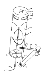
Referring initially to Figure 1 of the ~ _ ~nying
drawings, a moisture-sensing apparatus is illustrated
adapted to be mounted within the grain hopper of a combine
harvester. The illustrated apparatus includes a support
shoe 1 carrying spaced apart magnets 2, 3 intended to be
used to mount the support shoe on a sloping part of the
grain-carrying hopper of a combine harvester. The support
shoe may also be cnnn-~ct~ to a chain (not shown) which is
hooked to an ~yuL ~I~L iate anchorage point above the
illustrated ~ ~dLt~LUS within the harvester, to prevent the
p~aLc~Lus falling into the auger of the combine haLV~LeI
if the magnets should become ~7ic~ J~g~ d from the side of
the hopper. Pivotally connected to the support shoe 1 by
a tightenable bolt 4 is an upright arm 5 carrying a wing
nut 6 on a stud which i5 receivable in a slot 7 formed in
a subs~nti~lly horizontal arm 8. The arm 8 has one end
pivotally connected, by means of a pivot 9, to an upper
part of the shoe 1. By appropriately adjusting the
position of the stud carrying the wing nut 6 within the
slot 7 and by subsequently tiqht~ninq the wing nut the arm
S may be retained in a vertical position.
The arm 5 supports a vertical tubular housing 10.
The upper part of the tubular housing 10 is provided with
an upper end cover 11. The upper end cover 11 has a
subst~nti~lly horizontal transverse end wall 12, and a
rlc.r~nrsin~ tubular side wall 13 provided with a plurality of
oval inlet apeL LUL~=S 14 formed therein. The inlet
LLUL~S extend CiL..UIIEc:L~..Lially and have a length which
is greater than their width . Each ~IpeL LUL " may be
cnnci~lP~ed to lie in a substantially vertical (but curved
plane) .
Contained within the housing 10 is a spear 15 of
the type described in British Patent Sp~i f ~ e.tion No.
W095/14228 P~ 7C~
~ 2~7~97
_9_
2, 222, 683A. The spear extends vertically upwardly within
the housing and is retained in position by an appropriate
spider 16 shown in phantom, located adjacent the open
bottom of the housing 10. The spider has radially
extending arms, with open spaces between the arms.
The lower end of the spear 15 projects below the
open bottom of the housing 10 and a cable 17 emerges from
the lower end of the spear.
The described apparatus may be mounted in position
within the grain-containing hopper of a combine harvester,
preferably at a position which is not directly under the
input auger, so that grain entering the hopper does not
actually fall directly on to the described apparatus.
As the grain-containing hopper fills with grain,
the level of grain will rise, and the level of grain will
e the lower part of the housing 10, thus effectively
closing the spaces def ined between the arms of the
spider 16. As the level of grain cont;n~ c to rise, grain
will eventually start to enter the housing through the oval
CI~JC:L ~ULeS 14 . The Clp~:L LUL~:S 14 are .1 i ~ d to permit
the ready ingress of grain into the housing, but to prevent
the ingress of straw or other material entrained with the
grain as it enters the hopper of the combine harvester.
Grain will enter the housing 10 through the
a~t:L LULeSS 14 until the housing lO is full. Once the
housing 10 is completely full, the housing 10 and the
cover 11 having the horizontal upper wall 12 and the
pPn~lin7 ci~ w~l 1 13 will serve to prevent the packinq
density within the housing 10 from increasing further, even
if the level of grain within the hopper rises to a
conci~rable level above the top of the housing 10. Thus,
W0 95/14228 2 1 7 6 ~ 9 7 r~
--10--
the housing and the upper end cover serve to control the
packing density of grain within the housing adjacent the
spear. The '- - d ~L~ I''' generated in the grain is
effectively prevented from increasing the packing density
within the hou6ing 10 by virtue of the presence of the
horizontal upper wall 12 . Since the oval apeL Lu~es 14 lie
in vertical (but curved) planes the downward p~ eS~uLè
generated by the weight to the grain above the described
apparatus is not transferred to the grain inside the
housing 10 .
A sen60r 18 may be provided on the underside of the
horizontal upper wall 12 to sense when the housing 10 is
full of grain. The sensor may comprise a Piezo electric
tr~n~:cl~ o~ or may comprise some sonic or optical sensor
means. When the sensor provides a signal confirming that
the housing is full of grain a reading may be taken l~rom
the moi~Lu,~ E_..sing spear 15 thus determining the moisture
content of the grain in the housing 10.
The output from the spear may be supplied to a
display and/or printer in the cab of the combine harvester
to provide a substantially instantaneous read out of
moisture content, and/or may be supplied to a yield monitor
in the cab to provide a yield rate which is "corrected" for
the actual moisture content. The output from the spear may
also be used in other ways, and may be fed to a computer
controlling various f~lnl-eionc of the combine harvester.
If no sensor 18 is provided it is poF~;hlP to
monitor the output reading from the spear 15 to ~ rmin~
when the housing is full. The output will fluctuate as the
housing fills, and will then s~hi 1 i ~e when the housing is
~ -t~ly ~ull.
WO 95/14228 2 J ;~ ~ ~ 9 7 r~ CtC
When the hopper of the combine harvester i5 emptied
of grain, the level of grain within the hopper will fall
until the level of grain i8 below the level of the bottom
of the housing 10. Grain within the hou5ing 10 will then
flow out of the housing through the spaces defined between
the arms of the spider 16. The cycle of operation
described above may then be repeated.
It is to be noted that the output of the spear will
fluctuate as the housing 10 is emptied of grain. This
f luctuation can be monitored to ensure that the housing 10
empties when the grain hopper of the combine harvester is
emptied .
Referring now to Figure 2 of the A _ ,~nying
drawings, an alternative top part 11' for the housing 10 is
illustrated. This top part is not provided with a
horizontal upper wall and ap~LLuL~=s in a 11~p~-n-lin7 side
wall, but instead is an open topped tubular element
provided with two ;nnl ;nc~d baffles. The upper baffle 19 is
formed from a planar plate which is ; n~ n~ at an angle
greater than the repose angle of grain or other flowable
material which is to be utilised in conjunction with this
~ ; r L of the invention . The repose angle of a
flowable material is the angle formed by the sides of a
pile of the material generated by simply pouring the
material downwards on to a horizontal surface. Because the
baffle 19 is ;nnlin~l at an angle which is greater than the
repose angle, none of the material will tend to Al 1 Ate
on the ba~fle when a ~low is es~hl; chl~l through the
housing 10. The upper baffle 19 extends more than half-way
across the diameter of the upper part 11 ' of the
housing 10 .
W095114228 2 1 7~ 97 -12- ~ I l
The upper baf f le l9 is located above a lower
baffle 20 which is also formed from an ln~-1 {n~-A planar
plate. The lower baffle 20 is ;~c1 inP~A in the opposite
direction to the upper baffle l9, and is again inr 11n~A at
an angle which is greater than the repose angle of the
material to be utilised in conjunction with this: ~'i
of the invention. The lower baffle 20 extends
subst~nti~11y half-way across the ~1;; of the upper
part ll ' of the housing lO, so that in the region 21 there
is a degree of overlap Or the baffles l9.
Effectively the baffles define an inlet ap~L~UL~
which extends between the overlapped regions of the baffle,
lying in a substantially vertical plane.
The ~mhoA;~ ~ illustrated in Figure 2 will operate
in a very similar manner to that of the rl~nhoA;- ~ of
Flgure l. It is to be appreciated, however, that the
housing lO will not begin to fill with grain until the
level of grain within the hopper reaches the top of the
upper part ll' of the housing lO. The grain will then fall
over the top of the upper part ll' of the housing and flow
down across the top of the upper baffle l9, then being
directed to flow across the top of the lower baffle 20
entering the interior of the housing lO through the
aperture effectively defined between the two baffles.
When the housing is full of grain, the ~ sel~ce of
the baffles ~L~V~::II-S an increase in ~JL~5~U~ arising within
the housing lO when the level of grain above the top of the
housing lO increases. Thus the housing and the baffles
again provide means for controlling the packing density of
grain within the housing lO.
WO 95/14228 2 1 7 ~ 4 9 7 ~ A7~c
Figure 3 and 4 illustrate a modif ied c ' ';- of
the invention for use in sampling a flow of material.
The e~mhotl;~ ~ of Figures 3 and 4 comprises a
housing 10 with an upper part 11 having oval i~eL LUL~S 14
generally as described with reference to Figure 1.
However, in this illustrated ~ho~l;r t the spider 16 tas
can be seen more clearly in Figure 4 ), which supports the
shaft of the spear 15, is provided with a plurality of
op~n;nqC 22. A shutter disc 23 i8 provided located
adjacent the spider 16. The shutter disc 23 is also
provided with a plurality of apertures 24 which COL~ U~Id
with the opC-n;n~C 22. Nhilst, in one ~ho~; L means may
be provided for moving the shutter disc 23 manually, in
this e~mho~;r L the shutter disc 23 has a toothed exterior
25 which engages a gear wheel 26 through an access window
27 formed in the side of the housing 10. The gear wheel 26
is driven by means of a shaft 28 and an appropriate motor
(not shown). The motor and the gear wheel 26 are located
within a housing 29 mounted on the exterior of the housing
10. The shutter disc 23 may be positioned relative to the
spider 16 so that the openings 22 and 24 are aligned, or so
that op~n; n~c are off-set, or may be moved to an
in~ te position.
SuL~ ~ ul~ding the upper part of the housing 10 is a
conical funnel 30 having an open top 31. The open top is
provided with a substantially conical mesh or grid 32.
It is envisaged that the ~yal~.Lus of Figure 3 will
be located directly under a falling stream of grain or the
like. The conical mesh 32 has ap~,. LuLas therein
dimensioned to permit grain to pass through the ape:. LuLe:s
;snd fall into the funnel 30, but provides the function of
WO95/~4tt8 21 7~4 97 r ~ C
--14--
minimising the amount of straw or other mzterial present
within the grain from entering the funnel 30.
As grain enters the funnel 30, the funnel will
fill, and ir the funnel i5 completely full grain will 3pill
over the upper lip def lning the open upper mouth of the
f unnel 3 0 .
The grain within the funnel 3 0 will pass through
the apertures 14 into the housing 10. The shutter disc 23
may be moved to such a position relative to the spider 16
that the ~IpeLLuLt:6 24 are in a predetPrminpd hit-and-mis6
relati-~n~hi~ with regard to the <lpeLLUL~S 22 in the
spider 16 50 that the effective flow path through the
combination of the spider 16 and the shutter disc 23 is
adjusted to provide a prpd~tprm;np~ flow rate for grain.
Grain will thus leave the bottom part of the housing lO at
a predetermined rate and if grain is present in the
$unnel 30 grain will enter the top part of the housing 10,
through the a~=LLUL~S 14, at a CUrL.~ 1;n~ PredetPrm;nPC~
rate. The amount of grain within the housing 10 will be
substantially constant over a period of time, and the flow
rate of grain will be so slow through the housing that the
grain adjacent the operative parts of the spear 15 will be
substantially stationary thus PnAhl ;n~ the spear to provide
an accurate output. However, it will be appreciated that
since the housing 10 is continually being emptied, and
continually being re-filled from material from the
funnel 31, the spear provides an almost "instantaneous"
output relating to the moisture content of grain present
within the stream of grain being directed towards the open
mouth 31 of the funnel 30.
It is to be appreciated that the combination of the
housing and the funnel will control the packing density of
Wo 9~/14228 ~ 1 7 ~ ~ 9 7 P~
--15--
grain within the housing, since only a certain
predet~rminpd maximum amount of grain can be present in the
combination of the funnel and the housing. It is
preferred, however, for the housing to be of the design of
Figure l and Figure 2 with the top element or with the
ba f f les .
It is envisaged that instead of the described "hit-
and-miss" shutter arr~ I_ of Figure 4 an adjustable
iris could be utilised. The iris may be manually adjusted
or may be motor-driven.
Means may be provided automatically to pre-select
the size for the flow passage through the lower part of the
housing lO in ~ r~ntl~nre upon the nature of the grain to be
utilised in conjunction with the apparatus. For example,
for grain of a small size, such as oil seed rape, the flow
passage would be small, whereas for a more bulky grain,
such as wheat, the flow passage would be larger. If the
described apparatus is mounted in a combine harvester, an
~yy. ~y iate pre-s~lec~or may be provided in the cab of the
combine harvester to enable the operator to select the size
of the f low passage in accordance with the crop being
harvested .
It is envisaged that since moist grain is more
likely to "clog" than dry grain, means may be provided to
control the size of the flow passage through the housing lO
in L~ ,..se to the measured moisture content of grain
within the housing lO. Thus, if moist grain, having a
moisture content in exce3s of a predett~rmin~-d limit, is
present within the housing, the size of the flow passage
through the housing may be increased, in order to minimif:e
the risk clogging or hlor~kin~ of the flow path, whereas if
"dry" grain having a moisture content less than a
WO 95/14228 ~ 4 9 7 P l~ I ï 71~c
--16--
predefPrminPd moisture content is present within the
housing, the size of the flow path through the lower part
of the housing may be reduced in order to prevent grain
flowing through the housing too quickly.
The apparatus of Figures 3 and 4 may be associated
with a grain dryer, and if the grain has been "cleaned"
before it is dried the mesh 32 may be omitted. The signal
from the spear may be sllrpliPA to a central drLai.yl L
which automatically stops the dryer when a predetp7~ninp~l
moisture level has been reached, or which activates an
indicator, such as a flashing light or a buzzer, to
indicate that the grain is "dry".
It is thus to be appreciated that the apparatus
described may be inserted directly within a pipe or conduit
through which a mater$;~1 is flowing, when the moisture
content of that material i5 to be mea5ured- The dU~L'-L~5
may in~.U-~VLc~te the entire LVSS section of the pipe or
conduit or may pref erably incu. VUL ~ Le less than the entire
~:-v:,s-seuLion of pipe or conduit. Thus if the housing of
the apparatus described above becomes full of material, and
further material is f lowing the through the pipe or
conduit, then that further material may flow past the
housing .
Figure 5 illustrates a modif ied Pmi~oA i L of the
invention intended primarily for use in measuring the
moisture content of a material f lowing along a pipe or
conduit. Such material may comprise grain, such as
agricultural grain, but may also include any other
particular material such as manufactured food stuffs
inrlll~lin~ rice, pasta, dried vegetables and the like, or
other granular-type materials.
WO 95114228 2 1 7 ~ ~ 9 7 r~ A7~;7~
--17--
Referring to Figure 5, a vertical pipe or
conduit 40 is provided through which material is intended
to flow in a downward direction. An upper shutter
aLL_, t 41 is provided, which is associated with the
pipe 40, the shutter aLL~I J --~t 41 ;n~ ;n~ a shutter
blade 42 defining a through aperture 43 and a driving
---hAn;~ 44. The driving-.r- -n;~ is adapted to move the
shutter between open and closed positions. The upper
shutter 41 is shown in the "closed" position. The shutter
41, when in the open position permits material within the
pipe or conduit 40 to flow into a housing 45 defined
beneath the shutter 41. The housing 45 contains a spear 46
of the type described above which is supported by a spider
47 located in the lower part of the housing 45.
A sensor 48 is provided adapted to sense the level
of material within the housing 45. The sensor 48 may be of
any a~L~I,Liate design and may thus, for example, comprise
an optical sensor.
At the lower end of the housing 45 a second or
lower shutter aLL_,s ~ 48 is provided which is of the
same design as the upper shutter arrA, L 41. The lower
shutter arrAr ~ 48 is provided with a shutter blade 49
which defines a through O.~ L-ULe, that through aperture not
being visible in Figure 5, but instead being aligned with
the axis of the housing 45. The shutter 48 is provided
with a drive - -h~ni~-n 50. A pipe portion 51 extends from
beneath the second shutter 48 so that material within the
housing may flow ~ Ldly out of the housing 45 when the
second shutter ~8 is in the open position.
A electric lead 52 is directed out ~rom the
housing 45 carrying signals from the spear 46.
W095/14228 ~ ~ 7~ 7 E~
--18--
It is to be appreciated that in use of the
arr~ illustrated in Figure 5, initially the upper
shutter 41 will be in the open position and the lower
shutter 48 will be in the closed position. I~aterial
flowing through the pipe 40 will thus ~ te within the
interior of the housing 45. When the sensor 48 senses that
the housing 45 is substantially full the upper shutter 41
i8 moved to the closed po6ition. Thus the packing density
of the material present within the housing 45 is limited.
p~ r~5 may then be taken from the moisture
sensinq spear 46 to ~atpr~;np the moisture content of
material present within the housing 45. Subsequently, the
shutter 48 may be opened, permitting material within the
housing 45 to flow downwardly and outwardly away from the
housing through the pipe 51. The entire cycle of operation
may then be repeated.
It i8 to be appreciated that the cycle of operation
may be modif ied, with the lower shutter 48 always being
partly open, so that there is a continuous, but relatively
810w, flow of material out of the housing 45. The upper
shutter 41 may then be actuated simply to maintain an
a~ riate quantity of material within the housing at all
times .
Ref errlng now to Figure 6, the arrAr~ t of
Figure 5 i5 illustrated in conjunction with a principal,
subst~ntii-l ly vertical pipe or conduit 60. It is to be
seen that the pipe 40 terminates within the main pipe or
conduit 60 with an open upwardly directly mouth 61 adapted
to catch material moving vertically down the main
conduit 60. The conduit 51 returns material discharged
from the housing 45 into the main conduit 60.
Wo 95/14228 2 ~ 7 6 ~ 9 7 F~~ c
--19--
It is to be appreciated that in use of an
aLL~1, as shown in Figure 6, there is no risk of the
main conduit 60 be - i n~ blocked.
-
In many situations, the flow of material along aconduit, such as the conduit 60, will be erratic. From
time-to-time there will be very substantial f lows, but
during the intervening period the f low may be very
sp~l - 'ic. The described apparatus can be used to measure,
subs~nti~lly instantaneously, the moisture content of
material flowing through the conduit 60. The measured
moisture content may be used to control a manufacturing
process, or may be displayed. For example, if the moisture
content is too high, then the time material being
manufactured spends in a dryer may be increased.
Alternatively, if the moisture content it too low, a
procedure may be activated to add moisture to the material
at a subsequent point in the manufacturing plant.
Whilst the invention has been described with
reference to ~mho~l;r--~s in which a spear as described in
British Patent Specification No. 2,222,683A is used as the
operative moisture-sensing means, alternative moisture
sensing means may be used within the housing lO.
Whilst the apparatus ha6 been described with
specific reference to the mea~uL --t of moisture present
in grain, it is to be clearly understood that the apparatus
may be used f or measuring the moisture content of other
f lowable materials such as pulses, rape or even
manuf actured items .