Note: Descriptions are shown in the official language in which they were submitted.
WO95/13745 2 1 7 6 5 ~ 2 PCT~S94/12S46
.
l~S~KU~V IR T~MO~TER
The present invention generally relates to infrared
thermometers of the type used to measure body temperature by
collecting IR emissions from a patient's tympanic membrane,
and more specifically, a novel light wave guide packaging
system for higher accuracy and greater durability.
BACRGROUND OF T~E lNv~lON
IR thermometers are fast becoming a staple item in
health care operations and have revolutionized routine care
procedures by eliminating or dramatically reducing the lag
time associated with temperature determination in diagnosis.
As opposed to prior temperature measuring devices such as
conventional mercury thermometers, an IR thermometer is a
sophisticated optical - electronic assembly with precision
designed and assembled components requiring tightly
toleranced and exacting specifica-tions for proper operation.
Attention is directed to the teachings of U.S. Patent No.
4,797,840 entitled "Infrared Electronic Thermometer And
Method For Measuring Temperature" by Jacob Fraden, for a
general description of IR thermometer design and operative
characteristics. The teaching of the above-iden-tified
patent is incorporated by reference.
A critical aspect of IR thermometer operation is the
positional arrangement of the wave guide and the sensor
inside the body of the device. From a functional standpoint,
the wave guide acts to collect the radiation emanating from
the tympanic membrane of the patient's ear and accurately
guide this radia-tion to the sensor with ri n; ~1 external
influences. The sensor receives the guided radiation and
generates a temperature read-ing as characterized by the
quantum of radiation sensed. The accuracy of the resulting
reading depends in part on the purity of the IR radiation
W095/13745 PCT~S94/12546
21-~50~ ~
passed to the sensor by the wave guide. The performance of
the thermometer will therefore depend in great measure on the
design of the wave guide and its relationship with the other
components of the thermometer.
Another important consideration in system design is the
durability of the precisely arranged components. A system
that leaves the factory with acutely sensitive settings that
are quickly lost within the first few days of use has
significantly reduced value to the consumer. Indeed,
thermometers that become inaccurate through the normal
bumping and shaking encountered in daily use are of limited
value regardless of the initial accuracy from the factory.
It has, therefore, become a critical aspect of thermometer
design to devise an arrangement of opera-tive elements that
incorporates a ruggedness and durability sufficient to
withstand daily abuse in practice without signifi-cant loss
of performance.
To attain these objectives, much progress has been made
in packaging the electronics and electro-mechanical
components to withstand typical daily rigors of use. These
are important advancements that allow greater use of the
product at less cost and concern about abuse.
Notwithstanding this progress, IR thermometers remain prone
to loss of fidelity due to normal bumps. This fidelity loss
is often traced to the optics dis-cussed above, wherein heavy
handed use causes slight but signal disruptive misalignment
of the wave guide. Significant mis-alignment of the optics
will dramatically curtail the IR thermometers accuracy.
It was with this understanding of the problems
associated with prior optic system design that led to the
present inven-tion.
OBJECTS AND SUMMP.RY OF THE PRESEN~ lNV15~. ~ lON
It is an object of the present invention to provide an
apparatus for protecting the positional integrity of an optic
system used in conjunction with an IR thermometer.
=
WO95/13745 ~1 ~ 6 S 0 2 PCT~S94/12546
It is another object of the present invention to provide
a packaging arrangement that provides shock resistance to
optical elements arranged in an IR thermometer.
It is a further object of the present invention to
provide an arrangement of concentric elements and
specifically deline-ated spaces between the elements to
create a low impact resist-ant optical instrument.
It is yet another object of the present invention to
pro-vide a shock resistant wave guide that is economical to
manufac-ture and inexpensive to assemble.
The above and other objects are realized in a wave guide
system that combines precision optics with an external rigid
protective sheath. The outer sheath is positioned concentri-
cally around the wave guide but spaced therefrom, creating
a precisely ~ ioned gap between the wave guide and the
outer sheath. Within this annular gap, a semi-rigid spacer
is placed establishing line contact with both the outer
sheath and the inner wave guide. The line contact with the
inner wave guide is radially offset from the line contact
with the outer sheath thus creating a matrix of perpendicular
bending moments at regular intervals within the spacing
structure.
In accordance with the varying aspects of the present
invention, a continuous sleeve is positioned in the annular
space between the wave guide and the outer sheath, wherein
the sleeve has plural tabs extending therefrom, selectively
posi-tioned to permit slight deformation in response to
external forces, bumps or rough handling.
The foregoing features of the present invention may be
more fully appreciated in the context of a specific
illustrative example thereof presented in conjunction with
accompanying draw-ing of which:
pESCRIPTION OF THE FIGURE8
Figure 1 is a perspective view of an illustrative
sheathing arrangement in accordance with the present
WO95/13745 PCT~S94tl2546
~ 1 76SQ~ --
invention;
Figure 2A is a cross-sectional view of the embodiment
depicted in Figure l;
Figure 2B is a segment view of forces acting on a
portion of spacer 20;
Figure 3A is a second cross-sectional view of the
embodi-ment of Figure 1, under the influence of stress;
Figure 3B is a segment view of the spacer of 3A;
Figure 4 is a second embo~;r?nt, shown in cross-section
view;
Figure 5A is a third embodiment, shown in perspective
view; Figure sB is a further embodiment; and
Figure 6 is a depiction of an extrusion process for
making the embodiment of Figure 5A.
DESCRIPTION OF THB PRESENT lNv~N~l~lON
The present invention generally provides a shock
absorbing spacer to prevent physical distortions and damage
to the light trAn~;ssion medium in light-based analytic
instruments such as IR thermometers. The spacer is
positioned and configured within an annular gap between the
transmission medium and an outer sheath to form a series of
contact points that are radially off-set. By positioning the
supporting contact points in offset orientation, the
impingement of external forces on the trans-mission medium
are translated into bending moments along the perimeter of
the spacer -- thereby dissipating the force without
distortion to the transmission medium.
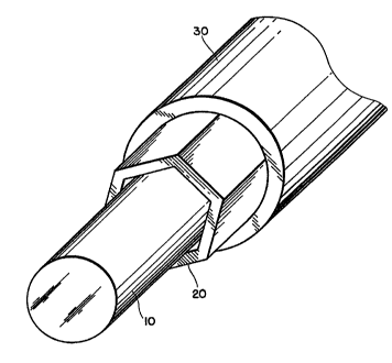
Turning now to the Drawing, Fig. 1 depicts the layered
arrangement of the transmission medium (wave guide or other,
depending on application), spacer and outer sheath. Specifi-
cally, a light transmission medium 10 having a generally
cylindrical shape is encased by a protective sheath 30 having
a generally circular inner diameter that is greater than the
outer diameter of the transmission medium forming an annular
gap therebetween. The spacer 20 is positioned in a snug fit
WO95/13745 2 ~ 7 6 5 ~ 2 PCT~S94/12S46
.
in this annular gap, wherein the spacer has a cross-sectional
shape that departs from both the outer surface of the
transmission medium and the inner surface of the protective
sheath. In this way, open areas are created between the
spacer 20, the protective sheath 30 and the transmission
medium.
The arrangement of Fig. 1 is depicted in cross-section
in Fig. 2A. As shown in cross-section, the spacer 20 is a
hexagon accurately held in place between outer sheath 30 and
the inner tr~n~ sion medium 10. This positioning
establishes contact points between the spacer and the
protective sheath at 23; and between the spacer and
transmission medium at 24. With this arrangement, open areas
are formed around the perimeter of the transmission medium,
e.g., 25 (between the spacer and sheath) and 26 (between the
spacer and transmission medium). The loca-tion of open areas
vis-a-vis the points of contact create moment arms along the
spacer as depicted in Fig. 2B. It is the ~o~nt arms thereby
created that act to absorb induced shock to the assembly by
partial deflection of the semi-rigid spacer 20. In Fig. 2B,
F(t) is the force vector imparted by the transmission medium
and F(s) is the counteracting force vector imparted by the
sheath.
Representative dimensions for the components depend on
the actual implementation of the system. For use in a IR
thermom-eter, the transmission medium will typically have a
diameter of 0.123/0.118 inches. The outer sheath will have
an inner diam-eter of approximately 0.158/0.154 inches.
Finally, in such an arrangement, the spacer will have an
"effective" diameter of 0.140 inches, a thickness of 0.008
inches and is preferably formed by extrusion using
polyurethane or nylon.
Turning now to Fig. 3A, the arrangement of Fig. 2 is
shown, but now undergoing an external force F(l) representing
a shock or bump to the assembly. This force acts to distort
the outer protective sheath from the circular cross-section
WO95/13745 ~ 5 a ~ PCT~S94112546
to a cross-section of generally elliptical shape. The
application of this force is, however, not translated to the
inner transmission medium. To the contrary, this medium
remains circular, as the external force is absorbed by the
counter balancing distortion of the spacer, and,
particularly, the deflection of the semi-rigid moment arms
within the spacer. This can be clearly seen in Fig. 3B
depicting a portion of spacer 20 undergoing force induced
deflection, via force vectors F(s) and F(t).
Turning now to Fig. 4, a second inventive arrangement
is shown, wherein the spacer 20 is completely contiguous with
the transmission medium lO, but spaced from the outer sheath
by acutely angled tabs 33. In this arrangement, induced
forces are absorbed by the deflection of the angled tabs.
Although only four tabs 33 are shown, the use of more tabs,
distributed around the perimeter of the spacer 20 is
contemplated.
In Fig. 5A, a ~urther inventive arrangement is shown,
one that can be assembled through the use of extrusion
techniques. In this arrangement, the spacer has an exterior
surface with a star-shaped cross-section and an interior
surface shaped to fit snugly over the transmission medium
without open areas. In this form, the absorption of forces
is accomplished via the flexible and/or compressible nature
of the material used to form spacer 20. Alternatively, the
spacer may have an interior surface with a cross-section
identical to that of its exterior ~i.e., star shaped) thereby
establishing open areas between the transmission medium lO
and the spacer 20 as depicted in Fig. 5B. In both
arrangements of Fig. 5, the outer sheath has a generally
cylindrical inner surface.
In Fig. 6, an extrusion molding technique for making the
foregoing arrangement of Fig. 5A is shown. In this process,
the transmission medium lO is passed through a first die 70
having an opening shaped to correspond to the outer shape of
the spacer. Thereafter, the extruded spacer 20 is fitted
WO9Stl3745 ~1~ 6 5~2 PCT~S94/12546
.
into a cylindrical sheath, thus forming the open areas
between the spacer 20 and the sheath (not shown).
The above descriptions are illustrative of the inventive
concepts and many modifications and adaptations thereof will
be readily apparent to those skilled in this art without
departing from the scope and spirit of the invention.