Note: Descriptions are shown in the official language in which they were submitted.
WO95/14913 ~ 7 6 5 ~ 4 PCT~S9~/12509
IMPROVED TYMPANIC T~RM~ .,~K
The present invention relates to temperature
measurement devices used in diagnostic and therapeutic
treatment. More par-ticularly, the present invention
relates to the use of special-ized sensor geometries to
create multiple viewing angles that enhance the accuracy
and repeatability of temperature readings taken from the
IR emissions radiating from the tympanic membrane of the
ear.
BACRGROUND TO THE lNv~ilON
Recent progress has been made in developing systems
for tympanic membrane temperature measurement. By way of
back-ground, mammalian temperature has long been of keen
interest to doctors and others involved in diagnosis and
lS treatment of patient pathologies. On the other hand,
accurate temperature measurement, accomplished in a quick,
unintrusive and inexpen-sive manner has remained a
considerable task. Measuring the temperature of the
tympanic membrane of the ear has been found to provide a
highly accurate body temperature reading. By collecting
the infrared emissions from the tympanic membrane, an
accurate temperature reading can be ascertained in an
unintru-sive procedure.
As stated above, many systems have been proposed for
tem-perature measurement based on tympanic IR emissions.
Exemplary patents in this field include U.S. Patent No.
4,895,164 to Wood, 4,797,840 to Jacob Fraden, Ph.D. and
U.S. Patent No. 5,199,436 to Pompei, et al.; the contents
of these patents are incorporated herein by reference.
These systems vary in both accuracy and complexity, but in
large have been found to be very useful for their intended
purposes, and are now enjoying commercial popularity.
Notwithstanding these past successes, a common and
WO95/1~913 2 ~ ~ 6 5 0 4 PCT~S9U12509 ~
significant handicap resides with even the most expensive
of these systems. This handicap relates to the accuracy
and repeatability of the readings obtained.
It has been found that the typical IR thermometer
will give a reading that varies in significant amounts
depending on the angle and depth of placement of the tip
vis-a-vis the ear canal. This variation is caused by
changes in the sensor position rela-tive to the wave
guide, the ear canal and tympanic membrane. More
particularly, the geometric relationship between the
sensor and the tympanic membrane will influence the
ultimate reading by the sensor in operation. As this
geometry changes, the sensor will encounter reading
fluctuations independent of actual mem-brane temperature.
These problems can be better visualized by reference
to the prior art probe design and its placement in a
typical ear canal-- see, e.g., Figures l and 2. In Figure
l, a simplified diagram depicts the general elements of an
IR type thermometer and its physical relationship with a
human ear. In this use, the ther-mometer develops a field
of view of the ear canal and tympanic membrane of the ear
as depicted in Figure 2. As can be appreci-ated, the
field of view of the thermometer will depend on the
position in terms of depth and angle as applied by the
user of the device.
In this regard, an angular displacement from
perpendicular will afford greater influence to the ear
canal wall, while a deeper placement of the probe into the
ear canal will lessen the influence of the ear canal vis-
a-vis the tympanic membrane. Ac-cordingly, different
readings will result from the same patient solely as a
function of thermometer placement in the ear. Of course,
ear canal dimensions will also differ amongst individ-
uals, adding an additional variance. The impact of these
vari-ances on typical temperature readings is illustrated
in Table I below - which delineates temperature reading as
WO95/14913 2 ~ ~ ~ 5 0i PCT~S94/12509
a function of probe position.
TABLE I
~nqle DePth Temperature
0 96
0 l mm 97O
20 0 95~
As noted above, this phenomenon is intimately related
to the field of view of the sensor system. This field of
view is influenced by several design aspects, chief of
these being the relative position of the sensor to the
wave guide. Other things being equal, a large diameter
wave guide positioned close to a small sensor will exhibit
a relatively wide field of view, while a narrow wave guide
positioned at a relatively greater distance from a larger
sensor (in terms of radiation impingement surface area)
exhibits a narrow field of view.
The impact of the field of view for the sensor system
can be expressed in the following way. Sensors with a
narrow field of view afford accurate readings relatively
independent of dis-tance from the target (depth of probe
in the ear) - but fluctu-ate to a greater degree in
temperature reading (and accuracy) when angle
2S displacements are introduced in sensor placement vis-a-vis
the ear. Alternatively, a sensor with a wide field of
view provides reciprocal properties. The wide field of
view sensor gives a reading relatively insensitive to
angle of probe placement--but is more sensitive to probe
depth. These princi-ples may be better visualized by
inspection of the graphs in Figures 3 and 4.
Although the above-noted dichotomy between narrow and
wide views provides a useful illustrative tool, it should
be noted that two sensors having the same viewing width
may, however, exhibit different views, as the angle of
view may be altered. The implication of these properties
WO9511~913 ~ ~ PCT~S9~/12~09
is that the various geometric sensor arrangements found in
prior art IR thermometers are prone to position dependent
reading variations.
OBJECTS AND 8UMMARY OF THE PRESENT l~v~llON
It is, therefore, an object of the present invention
to provide an IR thermometer having a sensor system that
compen-sates for probe placement and provides a repeatably
accurate temperature reading.
It is another object of the present invention to
provide an IR thermometer having a sensor system that
combines wide and narrow field of view readings thereby
compensating for differing angle and depth probe placement
in temperature measurement.
It is a further object of the present invention to
provide a sensor system and controlling logic that
incorporates multiple sensors having varying fields of
view to produce multiple read-ings for processing into a
depth and angle position independent accurate measurement
of body temperature.
It is yet another object of the present invention to
pro-vide a sensor system with controlling logic wherein
sensor data is correlated to compensate for angle and
depth position signal incongruence by system logic to
provide a singular temperature measurement.
The above and other objects of the present invention
are realized in a novel infrared thermometer employing a
partitioned sensor system for the development of at least
two signals relat-ing to differing fields of view of the
tympanic membrane of the ear. The sensor system includes
two or more separate sensors or IR receivers positioned to
collect different proportions of IR radiation from the
tympanic membrane. The multiple sensors have a varying
field of vision, e.g., ranging from wide to narrow, with
the level of variance specifically known and pre-selected.
The sensors are connected to a pre-programmed logic
W095/1~913 ~ 76~0~ PCT~S9~/12S09
, ,
device. The information is then correlated in a manner
that takes into ac-count the known difference in the field
of view for each sensor to arrive at a me~n;ngful
measurement of IR-source temperature.
In accordance with the varying aspects of the present
invention, the signal processor analyzes differences
between the readings from each of the separate sensors.
These differences are then used to select correction
values from a memory resident storage (e.g., look-up
table) or via separate determination us-ing an appropriate
processing algorithm. The corrective values are then
applied in generating an accurate and repeatable body
temperature reading for use in diagnosis and therapeutic
treat-ment of the patient.
The foregoing features of the present invention may
be more fully appreciated in the specific illustrative
embodiment as described hereinbelow in conjunction with
the following drawings of which:
DESCRIPTION OF THE FIGURES
Figures l and 2 depict the problems associated with
the prior art;
Figures 3 and 4 depict graphically the impact on
tempera-ture readings for wide and narrow field of view
designs;
Figure 5 presents a simplified structure of an IR
thermom-eter made in accordance with the present
invention;
Figure 6 provides a bimodal sensor geometry capable
of pro-ducing both wide and narrow fields of view within
the same wave guide;
Figure 7 illustrates the output for the bimodal
sensor de-sign of Figure 6;
Figure 8 depicts a bimodal sensor design for use with
a specific sensor system; and
Figure 9 provides an alternate sensor geometry.
WO9~/14913 2 1 ~ ~ ~ 0 4 PCT~S9~/12509
.
DESCRIP~ION OF THE PRESENT lNV~N~ ON
First, briefly in overview, the present invention is
di-rected to a sensor system that compensates for
different ear canal placement geometries by creating an IR
signal collected via both wide and narrow fields of view.
By using IR informa-tion that is responsive to a wide
field of view in conjunction with information from a
narrow field of view, the errors in temperature reading
occasioned by the vagaries in probe posi-tioning in the
ear can be compensated by appropriately pro-grammed signal
adjustment. Specifically, the signal processor integrated
with the sensor, weighs the input from both sources and
using a look-up table, applies corrective values to give
an accurate and repeatable temperature measurement.
With the foregoing overview in mind, attention is
directed to Figure 5 which provides a simplified diagram
of the salient elements in an IR thermometer. In this
illustrative diagram, the thermometer device provides a
housing 10 for containment of the operative elements of
the device. Specifically, the housing has an IR receiving
opening 15 at a terminus end thereof, posi-tioned to feed
incoming radiation to a wave guide 20. There are a
variety of possible wave guides available for use that
offer different performance characteristics in terms of
distortion and price, ranging from smooth gold-plated
tubes to fiber optic bun-dles. In functional terms, the
wave guide is designed to col-lect and pass incoming
radiation undisturbed, to IR sensor 30. Again, there are
several choices in sensor systems, including thermopile
types and pyroelectric elements. For purposes of this
presentation, the sensor of choice is the pyroelectric
sensor, which requires "matched pairs" to cancel out
signal contributions intrinsic with the pyroelectric
elements.
Continuing with Figure 5, the sensor 30 is connected
to processor 40 for converting the IR data into a high
WO95/14913 PCT~S9~/12509
~ 1 7~5~1~
quality temperature reading as will be described in more
detail below. In the context of the present invention,
the sensor design has been modified to create signals for
both wide and narrow fields of view. This is accomplished
by creating two or more sensors, each reporting separately
to the processor information on radi-ation.
The sensor geometry capable of this is depicted in
Figure 6. More specifically, the sensor 30 of Figure 5
is, in fact, two separate sensors, 32 and 34, each
connected to the processor 40. The first sensor 32 is
relatively smaller and concentric to the center line of
the wave guide 20, thus providing a narrow field of view.
The outer sensor 34, on the other hand, is some-what
larger and positioned outside the perimeter of the wave
guide - thereby providing a relatively wider field of
view.
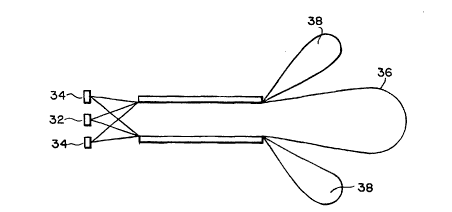
The above-noted outputs are illustrated in detail in
Figure 7, a cross-sectional view of the wave guide and
sensors. Spe-cifically, sensor 32 has a field of view
depicted by region 36, and sensor 34 has a field of view
depicted by region 38. These respective regions are
delineated by the relative position of the sensors and the
wave guide 20. As can be readily seen, wide and narrow IR
signal contributions can be developed by modifying the
geometry and placement of these sensors in the system.
Turning now to Figure 8, the above-noted sensor
geometry is depicted for a system of pyroelectric sensors-
-specifically, Figure 8A provides a frontal view of the
corresponding sensor design with sensors 32 and 34; Figure
8B likewise provides the same design as viewed from the
back, wherein the connectors to the processor are located.
The foregoing discussion has focused on multiple
fields of views as generated by independent sensors having
differing view "widths" (i.e., narrow or wide). The
principles of the inven-tion are also applicable to
independent sensors having differing fields of view
_
WO95/14913 ~ 0~ pcT~ss~/l25
wherein the difference is angular, not width. This
difference may be generated by the sensor design depicted
in Figure 9, which depicts a sensor assembly with four
separate IR receiving areas, lOl - 104.
Moreover, different fields of view may be generated
by the same sensor at different times. This can be
accomplished by shutter mechanisms, rotating lens or other
means of time modu-lating the radiation path between the
sensor and the tympanic membrane.
Correspanding to each geometry, the sensor is
connected to the processor for quantifying incoming IR
data and generating corrective values to properly align
the temperature measurement. In the above examples, the
multiple sensors reside in the same plane relative to the
wave guide. An alternative method for creating differing
fields of view involves changing the planer relationship
between the wave guide and one or more of the sensors.
However the arrangement is implemented, the system logic
is pre-programmed to adjust readings corresponding to the
geometry selected.
In this regard, the determination of corrective
values for processing of the IR data from two or more
sensors can be accom-plished by several techniques. For
example, assuming the two sensor system of Figure 8A, a
simplified look-up table can be generated and stored on-
board system memory. In this example, the temperature
from IR sensor 32 is subtracted from sensor 34 to give a
Delta sensor value. This value is then used to pull out
from the table a corrective value, Q, to add to the
tempera-ture reading from sensor 34 resulting in the final
displayed temperature reading, T. This relationship can
be expressed as an algorithm or in table form - as in
Table II below:
~ W095/14913 2 1 ~ ~ 5~4 PCT~S94/12509
TABLE II
T~34) - T(32) Q
>2.5 0
2 0.2
l 0.5
O 1.0
-l 2.5
-2 5.0
The above-described arrangement is merely
illustrative of the principles of the present invention.
For example, the above system is described in the context
of measuring incoming IR radiation. The approach
delineated above is also applicable to active sensor
designs wherein the sensor broadcasts an IR signal toward
the tympanic membrane corresponding, in part, to the
tympanic temperature. (See, Fraden, Patent No.
4,797,840). Similarly, this arrangement may be used for a
null net IR thermometer, wherein sensor and membrane
temperature are equilibrated. Numerous modifications and
adaptations thereof will be readily apparent to those
skilled in this art without departing from the spirit and
scope of the present invention.