Note: Descriptions are shown in the official language in which they were submitted.
21 76636
Tensioning and sealing apparatus for strapping an
object with a band
The invention relates to a tension and sealing
apparatus for strapping an object with a band according
to the preamble of the Patent Claim 1.
Such an apparatus is known from German Patent
Specification DE 32 29 870 C2. This document gives the
description of a band strapping apparatus in which a
single drive motor is provided for alternatively
driving the tensioning wheel and the sealing device,
which drive motor, together with a reduction gear
mechanism in a gear-mechanism housing can be positioned
as a structural unit on the housing of the band
strapping apparatus and can be connected thereto, with
the result that the drive device can be exchanged. The
drive motor and the reduction gear mechanism are
arranged parallel to one another and also parallel to
the tensioning shaft and are connected to one another
via gear wheels.
Further known apparatuses make use of angularly
arranged motors with worm gear mechanisms or so-called
Spiroid gear mechanism.
The object of the invention is to provide a tensioning
and sealing apparatus of the generic type in the case
of which the drive of the tensioning wheel is of a
simple construction and has a high efficiency.
Said object is achieved according to the invention in
that the tensioning wheel is driven with the aid of a
drive motor which is arranged coaxially with the
tensioning wheel and is connected to the tensioning
wheel via a gear mechanism arranged coaxially with the
tensioning wheel. This means that less friction losses
occur, with the result that a high overall efficiency
of the tensioning-wheel drive is achieved. In
addition, construction is simple and compact.
- 21 76636
- 2
Advantageous developments of the invention are given in
the subclaims.
According to one embodiment of the invention, the
tensioning wheel exhibits an inner cutout, at least
part of the gear mechanism being accommodated in the
cutout of the tensioning wheel. This means that a
large amount of space is saved.
According to a further embodiment of the invention, the
apparatus is provided with a separate drive motor for
the sealing device. Each motor can be adapted
optimally to the respective requirements.
According to a further embodiment of the invention, the
two drive motors can be fed by means of an accumulator.
The high efficiency of the tensioning-wheel drive
according to the invention permits cost-effective
accumulator operation.
An exemplary embodiment of the invention is explained
in more detail hereinbelow with reference to the
drawings, in which
Fig. 1 shows a perspective view of the apparatus
according to the invention,
Fig. 2 shows a sectional view of the apparatus
according to Fig. 1, and
Fig. 3 shows an exploded view, in perspective, of a
part of the apparatus of Fig. 1.
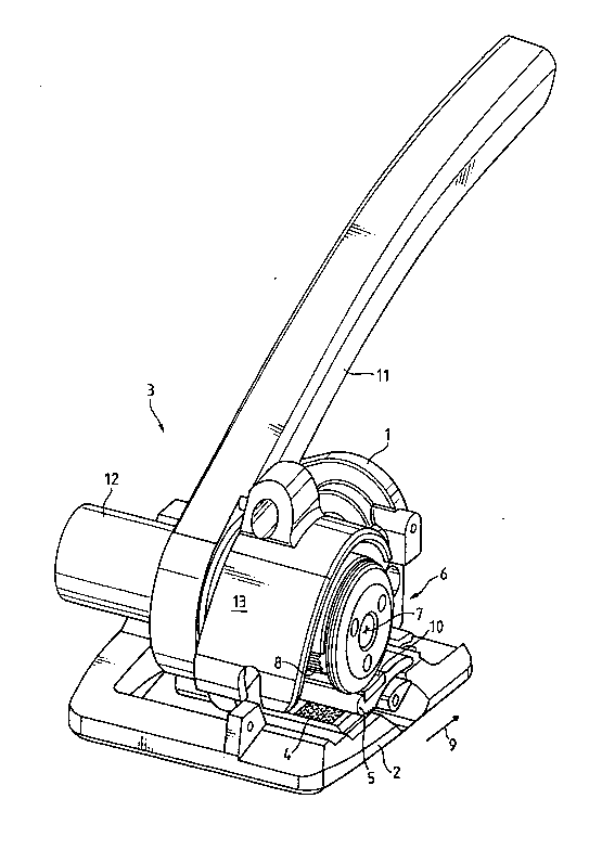
The tensioning and sealing apparatus according to the
invention is represented schematically in a perspective
view in Figure 1. It comprises a housing 1 with a base
plate 2 on which there are fastened a tensioning unit 3
and a sealing unit (not shown) which is known per se.
21 76636
,
-- 3
During use, the apparatus is positioned with the base
plate 2 on an object which is to be strapped with a,
for example, thermoplastic band. The band is laid
around the object, and two of its ends which are to be
sealed are retained by the tensioning unit 3. The
sealing unit is suitable for connecting, in a manner
known per se, the two mutually overlapping ends, for
example by friction welding, once the band has been
tensioned. If the band is unwound from a supply reel,
a severing device (not shown) of the tensioning unit 3
may be arranged downstream in order to sever the
required band section from the supply reel.
The tensioning unit 3 exhibits a fixed toothed plate 4
for bearing the lower band end which is to be sealed.
A movable tensioning shoe 5 is toothed on the underside
for interaction with the toothed plate 4. The upper
side of the tensioning shoe 5 exhibits a bearing
surface 10 which is suitable for bearing the upper band
end which is to be sealed. Furthermore, provision is
made for a pivotable rocker 6 with a toothed, drivable
tension wheel 8 which can be rotated about a tensioning
axis 7 and is intended for pressing the upper end of
the band against the tension shoe 5 and for gripping
the upper end upon rotation of the tension wheel 8,
with the result that the band is tensioned in the
tensioning direction 9 in a manner known per se.
In the exemplary embodiment shown, the axis of rotation
of the pivotable rocker 6 is arranged approximately
between the tensioning shoe 5 and the base plate 2 and
downstream of the bearing surface 10 of the tensioning
shoe 5, as seen in the tensioning direction 9.
Consequently, the rocker 6 with its tensioning wheel 8
can be raised again, without a large amount of force
being expended, in each use position of the apparatus,
in particular when the band is tensioned. However,
this arrangement of the rocker 6 is not fundamental to
the invention.
21 76636
_ - 4
The rocker 6 with the tensioning wheel 8 can be pivoted
by means of the actuation of a lever 11. When it is
pivoted rearwards in the tensioning direction 9, the
tensioning shoe 5 can be raised from the toothed plate
4, with the result that the lower band end which is to
be sealed can be introduced between the toothed plate 4
and the tensioning shoe 5. The lower band end is then
clamped in, and the tensioning wheel 8 is retained at a
distance from the tensioning shoe 5, with the result
that the upper band end which is to be sealed can be
introduced between the tensioning shoe 5 and the
tensioning wheel 8. If the rocker 6 is pivoted
forwards in the tensioni~g direction 9, the tensioning
wheel 8 is pressed against the bearing surface of the
tensioning shoe 5 and clamps in the upper band end,
with the result that the tensioning operation can be
carried out by the tensioning wheel 8 being rotated.
For tensioning the band when the tensioning wheel 8 is
bearing on the tension shoe 5, the tensioning wheel 8
is driven by means of a motor 12 which is arranged
coaxially with the tensioning wheel 8 and is connected
to the tensioning wheel 8 via a gear mechanism which is
likewise arranged coaxially with the tensioning wheel 8
and is known per se, for example a planet gear
mechanism. The rotational speed of the drive motor 12
is reduced to the desired amount with the aid of the
planet gear mechanism, which is mounted coaxially with
the tensioning axis 7 beneath the rocker cover 13.
This arrangement permits a very compact construction
and a high overall efficiency of the tensioning drive.
This is fundamental in the case of a tensioning unit
with accumulator operation.
Both the sealing unit and the tensioning unit 3 are
driven by motor, it being possible for the drive motor
12 of the tensioning device and also the motor of the
sealing device to be fed by an accumulator.
21 76636
_ -- 5
During the tensioning operation, the tensioning wheel
8, which is likewise mounted coaxially with the
tensioning axis 7, is driven by means of the motor 12,
with the result that it is rotated in the anticlockwise
direction and tensions the band in the tensioning
direction 9. A non-return lock (not shown) ensures
that the tensioning wheel 8 can be rotated only in the
tensioning direction 9. A sealing button (not shown)
is used, after the tensioning operation, to activate
the sealing unit for the friction welding of the ends
of the tensioned band. Since the sealing unit is
arranged downstream of the tensioning wheel 8, as seen
in the tensioning direct~on 9, the upper band end is
not tensioned in the sealing unit. This is
advantageous for the friction welding of the two
mutually overlapping ends of the band, since it is
easier to make a non-tensioned band section vibrate
than a tensioned one.
An electric motor or a compressed-air motor may be
used, for example, as drive motor 12. A brushless DC
motor, which can be actuated with the direct current of
the accumulator, is advantageously selected. The
torque of the drive motor 12 of the tensioning wheel 8
- can be adjusted, with the result that it is possible to
set corresponding band-tensioning ranges for different
objects which are to be strapped.
Figure 2 shows a sectional view of the apparatus
according to the invention. The drive motor 12 is, for
example, a brushless DC motor which is arranged
coaxially with the tensioning wheel 8 and with the gear
mechanism. In the embodiment shown, the gear mechanism
is a two-stage planet gear mechanism which is known per
se. The motor pinion 14 of the drive motor 12
interacts with the planet wheel 15 of the first
reduction stage. The planet wheels 15 of the first
stage are mounted on the planet wheel carrier 16 of the
21 76636
- 6 --
first stage. The rotational speed of the drive motor
12 is further reduced to the desired amount, and the
tensioning wheel 8 is driven, by means of the planet
wheel carrier 17 of the second reduction stage, the
pinion 18 of the second stage and the planet wheels 19
of the second stage.
The tensioning wheel 8 advantageously exhibits an inner
cutout, and part of the planet gear mechanism is
accommodated in a space-saving manner in said cutout.
For this reason, the tensioning wheel 8 is designed,
for example, as the lateral surface of a cylinder or in
the form of a ring or as a cylindrical ring, the inside
being configured in a toothed manner. The rocker 6 is
closed off by means of a cover 20.
The apparatus is provided with a separate drive motor
(not shown) known per se for the sealing device. As a
result, each motor can be adapted optimally to the
respective requirements. The two drive motors can be
fed by means of a single accumulator (not shown) which
is likewise known per se. Cost-effective accumulator
operation is permitted by the high efficiency of the
tensioning-wheel drive according to the invention.
An exploded view, in perspective, of the tensioning
drive of the apparatus is represented in Figure 3. The
planet wheels 15 and the planet wheel carrier 16 form
the first reduction stage. The planet wheel carrier 17
and the planet wheels 19 form the second reduction
stage. Of course, use may also be made of a different
gear mechanism, for example a harmonic drive.