Sélection de la langue

Search

Sommaire du brevet 2176636 

Énoncé de désistement de responsabilité concernant l'information provenant de tiers

Une partie des informations de ce site Web a été fournie par des sources externes. Le gouvernement du Canada n'assume aucune responsabilité concernant la précision, l'actualité ou la fiabilité des informations fournies par les sources externes. Les utilisateurs qui désirent employer cette information devraient consulter directement la source des informations. Le contenu fourni par les sources externes n'est pas assujetti aux exigences sur les langues officielles, la protection des renseignements personnels et l'accessibilité.

Disponibilité de l'Abrégé et des Revendications

L'apparition de différences dans le texte et l'image des Revendications et de l'Abrégé dépend du moment auquel le document est publié. Les textes des Revendications et de l'Abrégé sont affichés :

  • lorsque la demande peut être examinée par le public;
  • lorsque le brevet est émis (délivrance).
(12) Demande de brevet: (11) CA 2176636
(54) Titre français: APAPREIL DE MISE EN TENSION ET DE SCELLEMENT POUR L'ENRUBANNAGE D'UN OBJET
(54) Titre anglais: TENSIONING AND SEALING APPARATUS FOR STRAPPING AN OBJECT WITH A BAND
Statut: Réputée abandonnée et au-delà du délai pour le rétablissement - en attente de la réponse à l’avis de communication rejetée
Données bibliographiques
(51) Classification internationale des brevets (CIB):
  • B65B 13/02 (2006.01)
  • B65B 13/18 (2006.01)
  • B65B 13/22 (2006.01)
(72) Inventeurs :
  • STAMM, NIKOLAUS (Suisse)
  • FINZO, FLAVIO (Suisse)
(73) Titulaires :
  • ORGAPACK AG
(71) Demandeurs :
  • ORGAPACK AG (Suisse)
(74) Agent: MARKS & CLERK
(74) Co-agent:
(45) Délivré:
(22) Date de dépôt: 1996-05-15
(41) Mise à la disponibilité du public: 1996-11-27
Requête d'examen: 2001-11-23
Licence disponible: S.O.
Cédé au domaine public: S.O.
(25) Langue des documents déposés: Anglais

Traité de coopération en matière de brevets (PCT): Non

(30) Données de priorité de la demande:
Numéro de la demande Pays / territoire Date
01571/95-2 (Suisse) 1995-05-26

Abrégés

Abrégé anglais


A tensioning and sealing apparatus for strapping an
object with a band exhibits a tensioning unit (3) for
retaining and tensioning two ends of the band which are
to be sealed as well as a sealing unit for connecting
the two mutually overlapping ends. The tensioning unit
(3) has a motor drive (12) and comprises a tensioning
shoe (5) and a drivable tensioning wheel (8) which is
fastened on a pivotable rocker (6) and is intended for
pressing the band against the tensioning shoe (5) and
for gripping the same upon rotation. In order to
achieve a high overall efficiency of the tensioning
drive, the drive motor (12) of the tensioning wheel (8)
is arranged coaxially with the tensioning wheel (8) and
is connected to the tensioning wheel (8) via a gear
mechanism arranged coaxially with the tensioning wheel
(8).

Revendications

Note : Les revendications sont présentées dans la langue officielle dans laquelle elles ont été soumises.


- 7 -
Claims
1. Tensioning and sealing apparatus for strapping an
object with a band, which apparatus comprises a housing
(1) having a tensioning unit (3) for retaining two ends
of the bands which are to be sealed and for tensioning
the same and having a sealing unit for connecting the
two mutually overlapping ends, the tensioning unit (3)
exhibiting a tensioning shoe (5) and a drivable
tensioning wheel (8) which is fastened on a pivotable
rocker (6) and is intended for pressing the band
against the tensioning shoe (5) and for gripping the
same upon rotation, characterized in that the
tensioning wheel (8) is driven with the aid of a drive
motor (12) which is arranged coaxially with the
tensioning wheel (8) and is connected to the tensioning
wheel (8) via a gear mechanism arranged coaxially with
the tensioning wheel (8).
2. Apparatus according to Claim 1, characterized in
that the drive motor (12) for the tensioning wheel (8)
is an electric motor or a compressed-air motor.
3. Apparatus according to Claim 1 or 2, characterized
in that the tensioning wheel (8) exhibits an inner
cutout, and at least part of the gear mechanism is
accommodated in the cutout of the tensioning wheel (8).
4. Apparatus according to Claim 3, characterized in
that the tensioning wheel (8) is designed as a
cylindrical ring, the inner side being configured in a
toothed manner.
5. Apparatus according to one of Claims 1 to 4,
characterized in that the gear mechanism is a planet
gear mechanism (14, 15, 16, 17, 18, 19).
6. Apparatus according to one of Claims 1 to 5,
characterized in that the apparatus is provided with a

- 8 -
separate drive motor for the sealing device.
7. Apparatus according to Claim 6, characterized in
that the two drive motors can be fed by means of an
accumulator.
8. Apparatus according to one of Claims 1 to 7,
characterized in that the torque of the drive motor
(12) of the tensioning wheel (8) can be adjusted.

Description

Note : Les descriptions sont présentées dans la langue officielle dans laquelle elles ont été soumises.

21 76636
Tensioning and sealing apparatus for strapping an
object with a band
The invention relates to a tension and sealing
apparatus for strapping an object with a band according
to the preamble of the Patent Claim 1.
Such an apparatus is known from German Patent
Specification DE 32 29 870 C2. This document gives the
description of a band strapping apparatus in which a
single drive motor is provided for alternatively
driving the tensioning wheel and the sealing device,
which drive motor, together with a reduction gear
mechanism in a gear-mechanism housing can be positioned
as a structural unit on the housing of the band
strapping apparatus and can be connected thereto, with
the result that the drive device can be exchanged. The
drive motor and the reduction gear mechanism are
arranged parallel to one another and also parallel to
the tensioning shaft and are connected to one another
via gear wheels.
Further known apparatuses make use of angularly
arranged motors with worm gear mechanisms or so-called
Spiroid gear mechanism.
The object of the invention is to provide a tensioning
and sealing apparatus of the generic type in the case
of which the drive of the tensioning wheel is of a
simple construction and has a high efficiency.
Said object is achieved according to the invention in
that the tensioning wheel is driven with the aid of a
drive motor which is arranged coaxially with the
tensioning wheel and is connected to the tensioning
wheel via a gear mechanism arranged coaxially with the
tensioning wheel. This means that less friction losses
occur, with the result that a high overall efficiency
of the tensioning-wheel drive is achieved. In
addition, construction is simple and compact.

- 21 76636
- 2
Advantageous developments of the invention are given in
the subclaims.
According to one embodiment of the invention, the
tensioning wheel exhibits an inner cutout, at least
part of the gear mechanism being accommodated in the
cutout of the tensioning wheel. This means that a
large amount of space is saved.
According to a further embodiment of the invention, the
apparatus is provided with a separate drive motor for
the sealing device. Each motor can be adapted
optimally to the respective requirements.
According to a further embodiment of the invention, the
two drive motors can be fed by means of an accumulator.
The high efficiency of the tensioning-wheel drive
according to the invention permits cost-effective
accumulator operation.
An exemplary embodiment of the invention is explained
in more detail hereinbelow with reference to the
drawings, in which
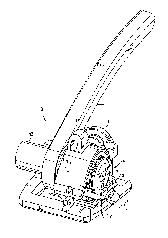
Fig. 1 shows a perspective view of the apparatus
according to the invention,
Fig. 2 shows a sectional view of the apparatus
according to Fig. 1, and
Fig. 3 shows an exploded view, in perspective, of a
part of the apparatus of Fig. 1.
The tensioning and sealing apparatus according to the
invention is represented schematically in a perspective
view in Figure 1. It comprises a housing 1 with a base
plate 2 on which there are fastened a tensioning unit 3
and a sealing unit (not shown) which is known per se.

21 76636
,
-- 3
During use, the apparatus is positioned with the base
plate 2 on an object which is to be strapped with a,
for example, thermoplastic band. The band is laid
around the object, and two of its ends which are to be
sealed are retained by the tensioning unit 3. The
sealing unit is suitable for connecting, in a manner
known per se, the two mutually overlapping ends, for
example by friction welding, once the band has been
tensioned. If the band is unwound from a supply reel,
a severing device (not shown) of the tensioning unit 3
may be arranged downstream in order to sever the
required band section from the supply reel.
The tensioning unit 3 exhibits a fixed toothed plate 4
for bearing the lower band end which is to be sealed.
A movable tensioning shoe 5 is toothed on the underside
for interaction with the toothed plate 4. The upper
side of the tensioning shoe 5 exhibits a bearing
surface 10 which is suitable for bearing the upper band
end which is to be sealed. Furthermore, provision is
made for a pivotable rocker 6 with a toothed, drivable
tension wheel 8 which can be rotated about a tensioning
axis 7 and is intended for pressing the upper end of
the band against the tension shoe 5 and for gripping
the upper end upon rotation of the tension wheel 8,
with the result that the band is tensioned in the
tensioning direction 9 in a manner known per se.
In the exemplary embodiment shown, the axis of rotation
of the pivotable rocker 6 is arranged approximately
between the tensioning shoe 5 and the base plate 2 and
downstream of the bearing surface 10 of the tensioning
shoe 5, as seen in the tensioning direction 9.
Consequently, the rocker 6 with its tensioning wheel 8
can be raised again, without a large amount of force
being expended, in each use position of the apparatus,
in particular when the band is tensioned. However,
this arrangement of the rocker 6 is not fundamental to
the invention.

21 76636
_ - 4
The rocker 6 with the tensioning wheel 8 can be pivoted
by means of the actuation of a lever 11. When it is
pivoted rearwards in the tensioning direction 9, the
tensioning shoe 5 can be raised from the toothed plate
4, with the result that the lower band end which is to
be sealed can be introduced between the toothed plate 4
and the tensioning shoe 5. The lower band end is then
clamped in, and the tensioning wheel 8 is retained at a
distance from the tensioning shoe 5, with the result
that the upper band end which is to be sealed can be
introduced between the tensioning shoe 5 and the
tensioning wheel 8. If the rocker 6 is pivoted
forwards in the tensioni~g direction 9, the tensioning
wheel 8 is pressed against the bearing surface of the
tensioning shoe 5 and clamps in the upper band end,
with the result that the tensioning operation can be
carried out by the tensioning wheel 8 being rotated.
For tensioning the band when the tensioning wheel 8 is
bearing on the tension shoe 5, the tensioning wheel 8
is driven by means of a motor 12 which is arranged
coaxially with the tensioning wheel 8 and is connected
to the tensioning wheel 8 via a gear mechanism which is
likewise arranged coaxially with the tensioning wheel 8
and is known per se, for example a planet gear
mechanism. The rotational speed of the drive motor 12
is reduced to the desired amount with the aid of the
planet gear mechanism, which is mounted coaxially with
the tensioning axis 7 beneath the rocker cover 13.
This arrangement permits a very compact construction
and a high overall efficiency of the tensioning drive.
This is fundamental in the case of a tensioning unit
with accumulator operation.
Both the sealing unit and the tensioning unit 3 are
driven by motor, it being possible for the drive motor
12 of the tensioning device and also the motor of the
sealing device to be fed by an accumulator.

21 76636
_ -- 5
During the tensioning operation, the tensioning wheel
8, which is likewise mounted coaxially with the
tensioning axis 7, is driven by means of the motor 12,
with the result that it is rotated in the anticlockwise
direction and tensions the band in the tensioning
direction 9. A non-return lock (not shown) ensures
that the tensioning wheel 8 can be rotated only in the
tensioning direction 9. A sealing button (not shown)
is used, after the tensioning operation, to activate
the sealing unit for the friction welding of the ends
of the tensioned band. Since the sealing unit is
arranged downstream of the tensioning wheel 8, as seen
in the tensioning direct~on 9, the upper band end is
not tensioned in the sealing unit. This is
advantageous for the friction welding of the two
mutually overlapping ends of the band, since it is
easier to make a non-tensioned band section vibrate
than a tensioned one.
An electric motor or a compressed-air motor may be
used, for example, as drive motor 12. A brushless DC
motor, which can be actuated with the direct current of
the accumulator, is advantageously selected. The
torque of the drive motor 12 of the tensioning wheel 8
- can be adjusted, with the result that it is possible to
set corresponding band-tensioning ranges for different
objects which are to be strapped.
Figure 2 shows a sectional view of the apparatus
according to the invention. The drive motor 12 is, for
example, a brushless DC motor which is arranged
coaxially with the tensioning wheel 8 and with the gear
mechanism. In the embodiment shown, the gear mechanism
is a two-stage planet gear mechanism which is known per
se. The motor pinion 14 of the drive motor 12
interacts with the planet wheel 15 of the first
reduction stage. The planet wheels 15 of the first
stage are mounted on the planet wheel carrier 16 of the

21 76636
- 6 --
first stage. The rotational speed of the drive motor
12 is further reduced to the desired amount, and the
tensioning wheel 8 is driven, by means of the planet
wheel carrier 17 of the second reduction stage, the
pinion 18 of the second stage and the planet wheels 19
of the second stage.
The tensioning wheel 8 advantageously exhibits an inner
cutout, and part of the planet gear mechanism is
accommodated in a space-saving manner in said cutout.
For this reason, the tensioning wheel 8 is designed,
for example, as the lateral surface of a cylinder or in
the form of a ring or as a cylindrical ring, the inside
being configured in a toothed manner. The rocker 6 is
closed off by means of a cover 20.
The apparatus is provided with a separate drive motor
(not shown) known per se for the sealing device. As a
result, each motor can be adapted optimally to the
respective requirements. The two drive motors can be
fed by means of a single accumulator (not shown) which
is likewise known per se. Cost-effective accumulator
operation is permitted by the high efficiency of the
tensioning-wheel drive according to the invention.
An exploded view, in perspective, of the tensioning
drive of the apparatus is represented in Figure 3. The
planet wheels 15 and the planet wheel carrier 16 form
the first reduction stage. The planet wheel carrier 17
and the planet wheels 19 form the second reduction
stage. Of course, use may also be made of a different
gear mechanism, for example a harmonic drive.

Dessin représentatif
Une figure unique qui représente un dessin illustrant l'invention.
États administratifs

2024-08-01 : Dans le cadre de la transition vers les Brevets de nouvelle génération (BNG), la base de données sur les brevets canadiens (BDBC) contient désormais un Historique d'événement plus détaillé, qui reproduit le Journal des événements de notre nouvelle solution interne.

Veuillez noter que les événements débutant par « Inactive : » se réfèrent à des événements qui ne sont plus utilisés dans notre nouvelle solution interne.

Pour une meilleure compréhension de l'état de la demande ou brevet qui figure sur cette page, la rubrique Mise en garde , et les descriptions de Brevet , Historique d'événement , Taxes périodiques et Historique des paiements devraient être consultées.

Historique d'événement

Description Date
Inactive : CIB de MCD 2006-03-12
Demande non rétablie avant l'échéance 2003-05-15
Le délai pour l'annulation est expiré 2003-05-15
Réputée abandonnée - omission de répondre à un avis sur les taxes pour le maintien en état 2002-05-15
Lettre envoyée 2002-01-11
Inactive : Dem. traitée sur TS dès date d'ent. journal 2002-01-11
Inactive : Renseign. sur l'état - Complets dès date d'ent. journ. 2002-01-11
Exigences pour une requête d'examen - jugée conforme 2001-11-23
Toutes les exigences pour l'examen - jugée conforme 2001-11-23
Demande publiée (accessible au public) 1996-11-27

Historique d'abandonnement

Date d'abandonnement Raison Date de rétablissement
2002-05-15

Taxes périodiques

Le dernier paiement a été reçu le 2001-05-02

Avis : Si le paiement en totalité n'a pas été reçu au plus tard à la date indiquée, une taxe supplémentaire peut être imposée, soit une des taxes suivantes :

  • taxe de rétablissement ;
  • taxe pour paiement en souffrance ; ou
  • taxe additionnelle pour le renversement d'une péremption réputée.

Les taxes sur les brevets sont ajustées au 1er janvier de chaque année. Les montants ci-dessus sont les montants actuels s'ils sont reçus au plus tard le 31 décembre de l'année en cours.
Veuillez vous référer à la page web des taxes sur les brevets de l'OPIC pour voir tous les montants actuels des taxes.

Historique des taxes

Type de taxes Anniversaire Échéance Date payée
TM (demande, 2e anniv.) - générale 02 1998-05-15 1998-05-07
TM (demande, 3e anniv.) - générale 03 1999-05-17 1999-04-28
TM (demande, 4e anniv.) - générale 04 2000-05-15 2000-05-03
TM (demande, 5e anniv.) - générale 05 2001-05-15 2001-05-02
Requête d'examen - générale 2001-11-23
Titulaires au dossier

Les titulaires actuels et antérieures au dossier sont affichés en ordre alphabétique.

Titulaires actuels au dossier
ORGAPACK AG
Titulaires antérieures au dossier
FLAVIO FINZO
NIKOLAUS STAMM
Les propriétaires antérieurs qui ne figurent pas dans la liste des « Propriétaires au dossier » apparaîtront dans d'autres documents au dossier.
Documents

Pour visionner les fichiers sélectionnés, entrer le code reCAPTCHA :


Pour visualiser une image, cliquer sur un lien dans la colonne description du document. Pour télécharger l'image (les images), cliquer l'une ou plusieurs cases à cocher dans la première colonne et ensuite cliquer sur le bouton "Télécharger sélection en format PDF (archive Zip)" ou le bouton "Télécharger sélection (en un fichier PDF fusionné)".

Liste des documents de brevet publiés et non publiés sur la BDBC .

Si vous avez des difficultés à accéder au contenu, veuillez communiquer avec le Centre de services à la clientèle au 1-866-997-1936, ou envoyer un courriel au Centre de service à la clientèle de l'OPIC.


Description du
Document 
Date
(aaaa-mm-jj) 
Nombre de pages   Taille de l'image (Ko) 
Dessin représentatif 1998-05-06 1 28
Abrégé 1996-08-25 1 24
Description 1996-08-25 6 288
Revendications 1996-08-25 2 55
Dessins 1996-08-25 3 118
Rappel de taxe de maintien due 1998-01-20 1 111
Accusé de réception de la requête d'examen 2002-01-10 1 178
Courtoisie - Lettre d'abandon (taxe de maintien en état) 2002-06-11 1 183