Note: Descriptions are shown in the official language in which they were submitted.
~t 767~4
-- WO 95/14839 PCTIUS94112930
PORTABLE SHELTER ASSEMBLIES
- BACKGROUND
This invention relates to portable shelter assemblies and more
particularly, to collapsible and exr~nl1~hle portable shelter assemblies.
In my prior U.S. Patent Nos. 3,968,808, 4,026,313,
5 4,290,244, 4,437,275, Re. 33,710, and 5,230,196 I have disclosed
interconnPctPd pentagonal, hexagonal, rectangular, or square sections or
modules for forming collapsible and expandable portable shelters. The
shelters formed by these modules are light in weight and adapted to be
quickly put up and taken down. The modules and shelters formed from the
10 modules disclosed in, for example, my U.S. Palent Nos. 3,968,808 and Re.
33,710 are self-supporting by virtue of a self-locking action reslllring from
the asymmetrical disposition of certain strut members forming the modules.
W_ile the self-locking aspect of these shelters is highly advantageous in
facilir~ting the fast and simple erection of such shelters, it is desirable to
15 provide a shelter having greater resi.ct~n~e to adverse conditions, such as
wind or snow, which tend to create stresses in the structures.
My U.S. Patent No. 5,230,196 provides a system including
modules formed of pivotably pinned pairs of struts arranged on the sides of
the modules. The strut pairs are pivotably ~tt~-`hP~ to engageable and
20 ~icpng~geable locking devices defining corners of the modules. When the
locking devices are disengaged, the modules are adapted to fold into a
bundle. When the modules are unfolded, the locking devices are m~nn~lly
engaged to form the expanded modules. The expanded modules including
m~nl~lly engaged locking devices exhibit enh~nre~ resistance to stress-
25 inducing conditions.
It is desirable to provide collapsible and e~r~n-l~hle modules
for forming portable shelters that are light in weight, and that exhibit great
resict~n~e to stress-inducing conditions. It is further desirable to provide
e~cran~l~hle and collapsible modules for forming portable shelters that are
21 767(~4
-- WO 95/14839 PCT/US94112930
adapted to be quickly put up at a site without tools, and are adapted to be
put up by workers at ground level, without the need for ladders, or other
similar e4uipl~ . It is further desirable to provide a portable shelter that is
easy to store and L~ OlL. It is further desirable to provide a set of
5 exp~n~ble and collapsible modules that are adapted to be combined in a
variety of ways to form a variety of dirrelcllt types of portable shelters. It is
still further desirable to provide exp~n-l~ble and collapsible modules for
forming self-supporting portable shelters requiring no internal obstructions.
It is still further desirable to provide expandable and collapsible modules of
10 one or more ~ypes that possess sufficient strength to be combined with one
another to form various types and sizes of portable shelters.
SUMMARY
In accordance with one aspect of the present invention, an
15 expandable and collapsible scissor assembly for an expandable and
collapsible structure is provided. The scissor assembly includes a first strut
having a first and a second end, a second strut having a first and a second
end, and means for limitin~ the first and second ends of the first and second
struts to movement in a substantially common plane, the first and second
20 struts overlying each other at a point in the plane. First means are providedfor preventing movelllcllL of the first end of the first strut away from the
second end of the second strut beyond a first exp~n~e~ ~lict~nre. Releasable
means are provided for releasably preventing movement of the second end of
the first strut away from the first end of the second strut beyond a second
25 expanded distance. The releasable means is releasable to permit movement
of the second end of the first strut away from the first end of the second
strut beyond the second expanded ~1ict~nre. First means are provided for
locking the first end of the first strut in a spaced relationship with the firstend of the second strut. Second means are provided for locking the second
_ wo 95/14839 . 2 1 7 6 7 G 4 Pcr/usg4/l293n
end of the first strut in a spaced relationship with the second end of the
second strut.
In accordance with a further aspect of the present invention,
an exr~n-l~hle and collapsible structural module is provided. The module
5 includes four interconn~cr~d strut pairs, each strut pair including a first strut,
the first strut having a first and a second end, and a second strut, the second
strut having a first and a second end. The first end of the first strut of each
strut pair is pivotably i~tt~r.h~d at an outer corner of the module to a second
end of a second strut of a prece~ing strut pair. The first end of the second
10 strut of each strut pair is pivotably att~rll~d at an inner corner of the module
to a second end of a first strut of a preceding strut pair. The strut pairs are
interconnPcte~1 such that first and second struts of each one of the strut pairsoverlie each other in a plane defined by each strut pair. First means are
provided for preventing movement of the first ends of the first struts away
15 from the second ends of the second struts beyond a first expanded distance.
Releasable means are provided for releasably preventing movement of the
second ends of the first struts of a first two non-adjacent ones of the strut
pairs away from the first ends of the second struts of the first two non-
adjacent ones of the strut pairs beyond a second exp~n~rd tli~t~nre. The
20 releasable means is releasable to permit movement of the second ends of the
first struts of the first two non-adjacent ones of the strut pairs away from thefirst ends of the second struts of the first two non-adjacent ones of the strut
pairs beyond tne second exr~n~ed ~i.ct~nre. Second means is provided for
preventing movement of the second ends of the first struts of a second two
25 non-adjacent ones of the strut pairs away from the first ends of the second
struts of the second two non-adjacent ones of the strut pairs beyond a third
expanded ~ist~nre. Means is provided for locking the outer corners in a
spaced relationship with corresponding ones of the inner corners.
21 76704
Wo 95/14839 PC rlUS94112930
In accordance with yet another aspect of the present invention.
an exr~n~l~ble and collapsible shelter is provided and includes a series of
interco.~ , çxp~n~hle and collapsible structural mo-lllles.
5 BRIEF DESCRIPTION OF THE DRAWINGS
The fe~t~l~s and advantages of the present invention are
further understood by reading the following detailed description in
co~ ction with the drawings in which like numerals inrljc~te similar
elçInentc and in which:
10FIGS. lA-lD are sch.om~tic perspec~ive views of shelters
according to embo~liment~ of the present invention;
FIG. 2A is a sch~rn~tic perspective view of the shelter of FIG.
lC in a completely folded condition;
FIG. 2B is a sch~om~tic perspective view of a framework for
15the shelter of FIG. lC in a fully erected condition;
FIG. 2C is a sch~m~tic perspective view of the erected
framework of FIG. 2B ~tt~rh~d to an inner cover;
FIG. 3 is a srh~m~tic front view of the frameworks of the
shelters of FIGS. lA-lD nested relative to one another;
20FIGS. 4A~C are srh~rn~tic front views of dirrerent types of
structural modules according to embo~imPnt~ of the present invention;
FIG. 5 is a pe~eCLi~e view of a structural module according
to an embodiment of the present invention in a folded condition;
FIG. 6 is a side view of a structural module according to an
25embodiment of the present invention in a collapsed and in an erected
condition;
FIG. 7 is a perspective view of a structural module according
to an embodiment of the present invention in an expanded condition;
FIG. 8A is a side view of a hub assembly according to an
30embodiment of the present invention;
WO 95/14839 2 1 7 6 7 0 4 PCI-/US94/12930
FIG. 8B is a side, partially cross-seclional view of the hub
assembly of FIG. 8A, taken at the section 8B-8B of the top view of the hub
assembly shown in FIG. 8E;
FIG. 8C is a side view of a blade housing for use with the hub
assembly of FIG. 8A;
FIG. 8D is a side view of portions of a spring biased blade
assembly for use with the hub assembly of FIG. 8A;
FIG. 8E is a top view of the hub assembly of FIG. 8A;
FIG. 8F is an exploded view of a portion of the hub assembly
of FIG. 8A;
FIG. 8G is a top view of a ring and strut blade for use with
the hub assembly of FIG. 8A;
FIG. 8H is a partially cross-sectional top view of a jacket
assembly, st~ut blade, and strut att~h~kle to the hub assembly of FIG. 8A;
FIG. 8I is an exploded, perspective view of the jacket
assembly, strut blade, and strut shown in FIG. 8H;
FIG. 9A is cross-sectional side view of a portion of a tension
lock means according to an embodiment of the present invention;
FIG. 9B is a partially cross-sectional view of the tension lock
20 means of FIG. 9A taken at section 9B-9B;
FIGS. 10A-lOF are srh~m~ti~ views of stages in the erection
of a shelter according to an embodiment of the present invention.
DETAILED DESCRIPTION
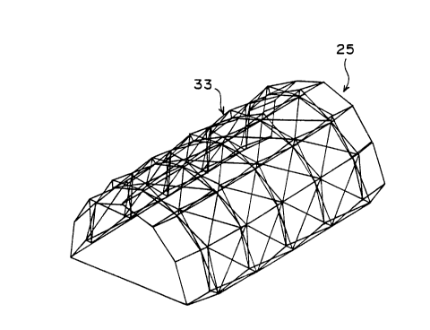
Expandable and collapsible modular shelters 21, 23, 25, and
27 according to embodiments of the present invention are seen in FIGS. lA-
lD, respectively. Using the shelter 25 of FIG. lC as an example, certain
- individual features common to all of the shelters are shown in FIGS. 2A-2C.
Each shelter 21, 23, 25, and 27 includes an expandable and collapsible
30 framework, 29, 31, 33, and 35, respectively. The &ameworks 29, 31, 33,
WO 9S114839 2 1 7 6 7 0 4 PCT/US9'1112930
and 35 of the shelters 21, 23, 25, and 27 are shown nested irLide of one
another for purposes of comparison in FIG. 3. The framework 33 of the
shelter 25 of FIG. lC is seen in FIG. 2A in its folded state and in FIG. 2B
in its exr~n~ state. An inner cover 37 is ~tt~rh~d inside the framework
5 33, as seen in FIG. 2C, and an outer cover 39 is ~tt~rh~ outside the
frarnework, as seen in FIG. 1C. Inner and outer covers corresponding to the
shapes of the frameworks 29, 31, and 35 are provided for the shelters 21,
23, and 27, respectively. The irmer and outer covers form a thermal barrier
and are preferably made of a flexible, ~Lc~roof, fire-reci.ct~nt and ultra-
10 violet recict~nt material.
The frameworks 21, 23, 25, and 27 are each formed ofcombinations of one or more of at least three types of structural modules,
namely, a 0 module 41, a 30 module 43, and a 60C module 45, seen
individually in ~IGS. 4A, 4B, and 4C, respectively. The 0 module 41, the
15 30 module 43, and the 60 module 45 are so named because of the angles
formed by horizontal sides of the modules, i.e., those sides of the module
intended to be substantially parallel with the ground. The 0 module 41 has
an exterior side 41' and an interior side 41" that are substantially the same
length between the horizontal sides 47, 49 such that a 0 angle between the
20 exterior corners 47', 49' and a~j~cent ones of the interior corners 47", 49"
of the horizontal sides is formed.
The 30 module 43 includes an exterior side 43' that is longer
than an interior side 43" between the horizontal sides 51, 53 such that a 15
angle between the exterior corners 51', 53' and adjacent ones of the interior
25 corners 51", 53" of the horizontal sides is formed, thereby totalling a 30
angle. The 60 module 45 includes an exterior side 45' that is longer than
an interior side 45" between the horizontal sides 55, 57 such that a 30
angle between the exterior corners 55', 57' and adjacent ones of the interior
corners 55", 57" of the horizontal sides is formed, thereby totalling a 60
30 angle. The vertical sides of the modules 41, 43, and 45 are preferably 0,
_- W095/14839 2 1 76704 PCrlUS94112930
i.e., the c~ ior and interior sides of the modules are suba~ lr;~lly the same
length bci~eell the ver~ical sides such that a 0 angle is formed between
exterior corners and ~ r~n- ones of the interior corners.
As can be seen in FIG. 3, the 0 module 41, the 30 module
5 43, and the 60 mo~llle 45 facilitate the co~l~ueLlon of a wide variety of
frameworlcs. It is understood, however, that additional modules having
holi~ull~l edges forming angles other than 0, 30, and 60 may be
provided to form frarneworks other than those specifically illustrated. For
e~mrle, U.S. Patent No. Re. 33,710, the disclosure of which is hereby
10 incorporated by reference, discloses tr~ncirion:ll modules having holizo~t~l
sides that total 90 angleâ. Moreover, if desired, modules having vertical
sides that form angles b~,iwec~ h~iOl and interior sides of the module may
be provided such as are disclosed in U.S. Patent No. 5,230,196, which is
incorporated by ~crt~ lce.
Each module 41, 43, and 45 preferably includes sub~L~"~ y
the same features. A generic module 61 is shown in a collapsed or folded
condilion in FIG. 5; in its movement between an int~rm~ te~ partially
collapsed condition, and a fully ~n~d condition in FIG. 6 (~tt~rh~d to
another module 21 '); and in a fully esrl~n~d condition in FIG. 7. It is seen
20 from the cn",l.,, ;con of FIGS. 6 and 7 that the modules 61 shown in those
drawings are somewhat dirrcr,~t. Specifir~lly, the module shown in FIG. 6
is a 30 module and the module shown in FIG.7 is a 0 module. It is
understood, however, that the description of the generic module 61 is
generally applicable to each of the prcfell~d types of modules 41, 43, and
25 4~, except where otherwise noted. The dir~clcnces between dle types of
modules 41, 43, and 45 are ~icc~-cse~ above, and are further ~iccllcsed
below.
- With reference to FIG. 7, it is seen that the module 61
inr~ eS four i,llelcolmrcte~l "scissors" or pairs 63, 65, 67, and 69 of struts.
30 The strut pair 63 includes strut 71 and 73; the strut pair 65 includes struts
-4~
WO 95/14839 2 ~ 7 6 7 G 4 pcrlus94ll293n
- 8 -
75 and 77; the strut pair 67 inrllldes struts 79 and 81; and the strut pair 69
inrlnries struts 83 and 85. Strut-c 75 and 77 and struts 83 and 85 of the strut
pairs 65 and 69, lc~ecLively, are preferably pivotably pinned to one another
by mearls 87 such as pins or rivets.
The strut pairs 65 and 69 define hull~o~tal sides of the module
61. For the plcf~ 0 modules 41, 30 modules 43, and 60 modules 45
the pivotable pi~ning means 87 is located at the center of the struts of the
strut pairs 65 and 69. As iicr~lssed below, when the module is fully
erected, the points at which the struts of the strut pairs 63 and 65 overlie or
intersect with one another in a 0 module 41, a 30 module 43, and a 60
module 45 are easily c~icnl~t~
The module 61 further inrll~d~s four hub assemblies 89, 91,
93, and 95 each pivotably ~tr~rh.od or co~ c~ i to two adjacent pairs of the
strut pairs 63, 65, 67, and 69. The hub assemblies 89, 91, 93, and 95 each
include an outer hub assembly 89', 91', 93', and 95' that mates with an
inner hub assembly 89", 91", 93", and 95". The struts 73 and 75 are
pivotably ~tt~rh~l or col~n~led, at sllbst~nti~lly right angles to one another,
to the outer hub assembly 89', and the struts 71 and 77 are pivotably
~tt~rh-od, at subst~nti~lly right angles to one allulller, to the inner hub
assembly 89". In like fashion, the struts 77 and 79 are pivotably att~chP~ to
the outer hub assembly 91', and the struts 75 and 81 are pivotably att~rh~d
to the inner hub assembly 91". The struts 81 and 83 are pivotably att~rhpd
to the outer hub assembly 93', and the struts 79 and 85 are pivotably
att~rhPd to the inner hub assembly 93". The struts 85 and 71 are pivotably
~tt~rhtod to the outer hub assembly 95', and the struts 83 and 73 are
pivotably att~rh~d to the inner hub assembly 95".
The circumscribing struts of the strut pairs 63, 65, 67, and 69
are preferably woven in a parlicular pattern to distribute bending actions on
the struts evenly while ass~lnng that the ir~er and outer hub assemblies are
in spaced registry with each other when the frameworlc is expanded. As
WO 95/14839 2 t 7 6 7 0 4 PCI/US94/12930
seen with rcfelence to FIG. 7, the weaving pattern results in the successive
struts 73, 75, 81, and 83 being disposed, at the point of intersection (i.e.,
where those struts overiie one another) with the corresponding succeccive
struts 71, 77, 79, and 85, le~e~ ely, on the interior of the module 61.
The hub assemblies 89, 91, 93, and 95 are preferably all
subst~nti~lly i~nti~l, such that ~iCc~lcsion of one of the hub assemblies
applies to all of the hub assemblies, except as otherwise in~ir~t~. The
Ç~,dlules of a hub assembly according to a ~lcfell~d embodiment of the
invention are shown with lcfelcnce to FIGS. 8A-8G, using the hub assembly
89 for purposes of discussion.
As seen in FIGS. 8A and 8B, the outer and inner hub
assemblies 89' and 89" include hubs 97 and 99, respectively, secured at a
rlict~n~e from one another at outer ends of outer and inner portions 101 and
103, respectively. The outer and inner portions 101 and 103 form parts of a
compression lock assembly 105 that locks the outer and inner hub assemblies
89' and 89" together when the module 61 is unfolded and tne outer and
inner hub assemblies are coll~ ssed together. The outer and inner portions
101 and 103 are preferably hollow tubular members and are locked together
by a spring biased blade assembly 107 of the compression lock assembly
105.
The blade assembly inrl~lde,c a blade holder 109, seen in FIG.
8C, and a pair of blades 111 and 113, seen in FIG. 8D, pivotably mounted
at first ends 115 and 117 thereof, respectively, by a collar and/or pivot pin
119, in a cavity 121 (shown in FIG. 8C without the blades) formed in the
blade holder. One or more torsion springs 123 are disposed around the pivot
pin 119 to urge second ends 125 and 127 of the blades 111 and 113,
respectively, in opposite directions radially out of the cavity 121 of the bladeholder 109. The blades 111 and 113 are preferably provided with bores or
other means, such as protruding portions 111' and 113', for holdin_ ends of
30 the torsion spring 123. Ends of the torsion spring 123 press ~gainct, for
WO95/14839 ~ ~ 76704 PCT/USg4ll293n
.
- 10 -
example~ the protruding portions 111' and 113' to urge the blades 111 and
113 radially out of the cavity 121. Button portions 129 and 131 are disposed
at, and preferably formed on, the second ends 125 and 127 of the blades 111
and 113, r~l.eiLi~ely.
As seen in FIGS. 8A and 8B, the blade assembly 107 is
secured in an inner end of one of the outer and inner portions 101 and 103
such that the second ends 125 and 127 of the blades 111 and 113 extend a
small ~i~r~n-~e outside of the outer or irmer portion. The blade assembly 107
is preferably secured in the outer or inner portion 101 or 103 by the pivot
10 pin 119 which, if desired, passes through a collar on which the blades 111
and 113 are pivotably mounted. The blade assembly 107 may, however, be
secured in the outer or inner portion 101 or 103 by any other a~lol,liate
means, such as by a separate pin or rivet, by a threaded connection, or by a
colllpl~s~ion fit.
In the hub assembly 89 shown in FIGS. 8A and 8B, the blade
assembly 107 is shown secured inside the outer portion 101. The inner
portion 103 receives a male leading end 133 of the blade holder, along with
the button portions 129 and 131 and the second ends 125 and 127 of the
blades. The button portions 129 and 131 are preferably formed with
chamfered ends 135 and 137 such that, as the second ends 125 and 127 of
the blades, which are normally biased radially o~lLw~dly by the torsion
spring 123, are inserted into the inner portion 103, the second ends of the
blades are retracted into the cavity 121 of the blade holder 109.
The wall 139 of the inner portion 103 is formed with a pair of
opposed apertures 141 and 143. When the leading end 133 of the blade
holder 109 is inserted to a sufficient depth in the inner portion 103, the
button portions 129 and 131 are urged radially outwardly by the torsion
spring 123 into the apertures 141 and 143, respectively, to lock the outer
portion 101 to the inner portion. When it is desired to separate the outer
portion 101 from the inner portion 103, the button portions 129 and 131 are
wo ss/l4s39 2 1 7 6 7 0 4 PCT/USg4ll293n
preferably m~ml~lly compressed into the aperlures 141 and 143 and the outer
portion and the inner portion are drawn axially apart from one another.
The button portions 129 and 131 on the blades 111 and 113
preferably extend out of the outer portion 101 and into the inner portion 103
5 a sufficient ~ict~nre to minimi7e risk of failure of the portion of the wall 139
of the inner portion between the apertures 141 and 143 and the end of the
irmer portion when the locked inner and outer portions are placed in tension.
Further, the male leading end 133 of the blade holder 109 preferably extends
into the inner portion 103 a sufficient ~ict~nre to m~ximi7~ the ability of the
10 locked inner and outer portions to absorb bending forces. Compression lock
assemblies according to the present invention have been observed to
withct~n~ tension forces of up to 600 pounds. The compression lock
assembly 105 facilitates the formation of larger shelters than was previously
practical, in that modules formed with hubs including such compression lock
15 assemblies have sufficient strength to withstand large loads due to forces
such as wind, snow, etc.
As seen in FIGS. 8A and 8B, the hubs 97 and 99 of the hub
assembly 89 are preferably subst~nti~lly identical to one another, except as
otherwise indicated. Hubs adaptable for use in cormection with the present
20 invention are disclosed in U.S. Patent No. 4,280,521, the disclosure of
which is hereby incorporated by ~efelellce. Other hubs adaptable for use in
connection with the present invention are disclosed in U.S. Patents No.
4,838,003, which is also hereby incorporated by reference. As seen in FIG.
8E, referring to the hub 97 for purposes of discussion, the hubs preferably
25 include one or more radial slots 145, preferably eight slots, for pivotably
mounting strut blades 147. The strut blades 147 are seen in FIGS. 8B, 8F,
and 8G.
As seen in FIGS. 8B and 8F, the hub 97 preferably includes a
top half 149 and a bottom half 151, having mating faces 153 and 155,
30 respectively. The mating faces 153 and 155 are each formed with mating,
WO95114839 2 1 76704 PCI/US94/12930
ring-snaped, half-circular grooves 157 and 159, respectively, seen as dashed
lines in FIG. 8E. The top half 149 and t'ne bottom half 151 are each forrned
with portions 145' and 145", l~3pe~;Li~ely, of tne slots 145 so tnat, when tne
top half and the bottom nalf are att~rh~d to one another, t'ne slots in tne hub
97 are formed. Bores 161 are formed in tne strut blades 147 for receiving a
ring 163, as seen in FIGS. 8B, 8F, and 8G. One or more strut blades 147
are provided on each ring 163. The ring 163 is clamped between the mating
faces 153 and 155 in the grooves 157 and 159 with the s~ut blades 147
received in desired ones of tne slots 145. The strut blades 147 pivot in the
slots 145 relative to the hub 97 on the ring 163.
The strut blades 147 are preferably flat members, formed
from a strong material such as sheet metal. An exterior bore 165' and an
interior bore 165" are formed in the strut blades 147 for mounting the
struts. The struts that are mounted on the strut blades 147 are preferably
cylindrical t~lbular members, with cylindrical interior openings. A jacket
assembly 166, seen in FIGS. 8H and 8I, is preferably provided for mounting
tne struts on the strut blades 147 and minimi7ing play between the struts and
the strut blades. The mounting of the strut 79 on a strut blade 147 is shown
by way of illustration in FIGS. 8H and 8I.
Each jacket assembly 166 preferably in~llldes a male end 167
receivable in the interior opening of a strut, the male end extenl1ing from a
flanged end 168 that is not able to enter tne cylindrical opening of the strut.
Each jacket assembly 166 preferably includes a pair of i-lentic~l jacket halves
169, 169 that are placed on opposite flat sides 147A, 147B of a strut blade
147. Each jacket half 169 is further formed with one bore 170 that aligns
witn the exterior bore 165' of a strut blade 147 and one bore 171 that
preferably extends from an inner face 172 of tne jacket half 169 to a
predetermined depth and that aligns wit'n the interior bore 165" in the strut
blade. A pin or rivet 173 is provided and fits in the bores 171 in each of the
woss/l483s 2 1 7 6 7 0 4 Pcr~usg4/l293~)
jacket nalves 169, 169 and through the interior bore 165" in the strut blade
147 to orient the jacket halves relative to the strut blade.
The struts are formed with bores 174 that align with the
exterior bore 165' of tne strut blades and the bores 170 of the jacket halves
5 169, 169. A st.-ut, a jacket, and a strut blade are fixed together by means
175 such as rivets, bolts, pins, etc. A plastic sleeve 176 (not seen in FIG.
8I) naving bores that align witn the bores 170 of the jacket halves 169, 169,
the exterior bore 165' of the strut blade 147, and tne bores 174 of the struts
is preferably inserted in the strut before the male end 167 of the jacket
10 assembly 166 and has an interior diameter subst~nti~lly equal to the exteriordiameter of tne jacket assembly to provide a tight flt. The jacket halves 169,
169 may be for ned from any suitable material, such as a rubber or plastic
material, or a met~llic material. As disclosed in U.S. Patent No. 4,280,521,
the jacket halves 169, 169 may also be formed of a deformable material such
15 that the struts may be att~-h~ to the strut blades 147 by being crimped so
that the jacket material compresses around the strut blades to secure the
struts to the strut blades.
The top half 149 and the bottom half 151 of the hub 97 are
preferably fastened to one another by nuts 177 and bolts 179, seen in FIGS.
20 8B, 8E, and 8F, received in openings 181 and 183, respectively, foImed in
the bottom half and the top half, lcs~ecLively, of the hub. Four sets of nuts
177 and bolts 179 preferably fasten the top half 149 and the bottom half 151
together. As seen in FIGS. 8B and 8F, the opening 183 for receivirlg the
bolts 179 is preferably coullL~l~unk for providing a bearing surface for the
25 bolt head 185. The bolt head 185 is preferably a m~chinlo screw-type head
such as screw-type head or a socket-type head capable of being driven by a
screw driver or an Allen wrench so that the bolt head is able to be turned
- when it is sunk into the opening 183. The nuts 177 preferably include an
internally threaded shank portion 187 for receiving the threaded portions of
30 the bolts 179 and a headed portion 189 disposed at the end of the shank
- _ WO95/14839 21 76704 PCI/US94/1293n
- 14 -
portion for bearing against an outside surface 191 of the bottom half 151.
The headed portion 189 is preferably hexagonal or any other suitable shape
for being held by a conventional wrench.
The hub 97 is secured to the outer porlion 101 of the
S colllpre~,~ion lock assembly 105 when the top half 149 and the bottom half
151 of the hub are f~ct~n~cl together by the nuts 177 and bolts 179. As seen
in FIG. 8F, a bore 193 is formed through the outer portion 101 near an
outer end 195 of the outer portion and a pin 197 is fitted in the bore. The
bottom half 151 and a portion of the top half 149 are formed with
10 substantially central, axial openings 199 and 201, respectively, for receiving
the outer end 195 of the outer portion 101. At least one of the mating faces
153 and 155 of the top half 149 and the bottom half 151 of the hub are
formed with radial grooves 203 (seen in FIG. 8F for the bottom half only)
for receiving the pin 197. When the top half 149 and the bottom half 151
15 are f~ct~n~cl together by the nuts 177 and bolts 179, the hub 97 is secured in
position relative to the outer portion 101 by the pin 197 clamped in the
grooves 203 between the mating faces 153 and 155.
The outer hub assembly 89' and the inner hub assembly 89"
each preferably further include subst~nti~lly i~1entic~1 means 205 for holding
20 the outer cover 39 and the inner cover 37, respectively, in position relative to the hub assembly 89. The inner and outer covers 37 and 39 are
preferably suitable flexible cover materials, and cover holders 209, seen in
FIG. 8B (not showing the inner cover 37), are ~ch~ in applopliate
locations on the inner and outer covers for fastening the covers to the hub
25 assemblies of the framework of the particular shelter type.
As seen in FIG. 8B, the cover holder 209 (shown by dashed
lines attached to the outer cover 39 in a position prior to insertion in the hub97, and in solid lines inserted in the hub, without the outer cover, which is
not shown for clarity of illustration) of the cover holding means 205 includes
30 a male portion 211 extending, at a first end of the male portion, from a
wo ss/14839 2 t 7 6 7 0 4 Pcr/uss4/12s30
flanged portion 213. The flanged portion 213 is preferably secured in
position relative to the cover 39 bclween the cover and a patch 39A having a
central opening 39B throu~h which the male portion 211 extends by heat
sealing the patch to the cover. The male portion 211 includes a substantially
5 T-shaped, radially flared second end 215, having a pair of opposed grips
217. The male portion 211 is preferably subst~nti~lly rectangular, and is
preferably wider in the direction of the grips 217 than in the direction
perpen~lir~ r to the grips.
The hub 97 is formed with a keyed axial opening 219 in a
10 portion of the top half 149, aligned with the opening 201 for receiving the
outer end 195 of the outer portion 101. The keyed opening 219 is formed to
permit the flared second end 215 of the male portion 211 of the cover holder
209 to pass through the keyed opening when the cover holder is oriented in
one direction, but not when the cover holder is oriented in any other
15 direction. When the second end 215 of the cover holder 209 is properly
oriented and is inserted through the keyed opening 219 and into outer end
195 of the outer portion in the opening 201 of the top half 149, and the
cover holder is turned axially, the grips 217 at the second end of the cover
holder are covered by flanged portions 221 of the keyed opening that prevent
20 the cover holder from being axially withdrawn from the hub 97. When the
cover holder 209 is turned so that the grips 217 are not covered by the
flanged portions 221, the cover holder may be axially withdrawn from the
hub 97.
Cover holders 209, preferably equal in number to the number
25 of hub assemblies forming the particular shelter type, are secured to the
inner and outer covers 37 and 39 for attaching the covers to the hub
assemblies. The covers 37 and 39 are preferably sufficiently flexible to
permit the cover holders 209 to be properly oriented by hand for insertion
into the corresponding keyed openings 219. Preferably, upon release of the
30 cover holders 209, after insertion into the correspondin~, keyed openings, the
wo 9S/14839 2 1 7 6 7 0 4 pcrlus94ll293n
- 16 -
normal tension in the covers 37 and 39 causes the covers holders to reorient
themselves such that they are not removable from the keyed openings, e~ccept
on purpose.
In the module 61 shown in FIGS. 5-7, and as in U.S. Patent
5 No. Re. 33,710, the disclosure of wnich is incorporated by l~,f~ ce, the
sum of the ~ t~nres from an inner hub assembly, e.g., inner hub assembly
89", along a strut extending ~ erlo~ll, e.g., strut 77, to the point where the
strut 77 crosses tne strut 75, e.g., at the pivotable pilming means 87, and
back, along the strut 75, to the outer hub assembly 89', is preferably the
10 sarne for all struts fo,~.~ning the module at all times. Ithis feature holds true
even though, for the different modules, i.e., the 0 module 41, the 30
module 43, and the 60 module 45, the intersection points for at least the
vertical sides of those modules, i.e., where the struts of those modules
forming the vertical sides of those modules cross, differ.
As noted above, the pivotable pinning means 87 on the strut
pairs 65 and 69 is preferably located at substantially the mid-point of the
struts 75, 77, 83, and 85. All of the struts 71, 73, 75, 77, 79, 81, 83, and
85 are preferably the same length. When the module 61 is in a fully erected
condition, in a 0 module, the struts 71 and 73 of the s~ut pair 63 and the
20 struts 79 and 81 of the strut pair 67 il~ e-;l at substantially the mid-points
of those struts. In erected 30 43 modules and in 60 modules 45, however,
the struts of the strut pairs 63 and 67 intersect at a ~ict~nre from the outer
hub assemblies 89', 91', 93', and 95' that may be determined according to
the following relationship:
L,=1/2xL(sin[cos~ (Ccos01)/L]~Csin~l))/cos(90-cos~ [(Ccos~l)/L])
25 where:
L, = ~ict~n~e from the outer hub assembly to the point of
intersection;
L = length of strut;
C = lengtn of hub assembly; and
wo gs/l4s3s 2 1 7 6 7 0 4 PCI~/US94/1293~
el = angle at hol-zolltal sides of module (i.e., 15 for 30c
module; 30 for 60C module).
Tension lock means 223 is provided to prevent movement of
- the ends of the struts of the strut pairs 63, 65, 67, and 69 relative to one
S another beyond pre~e~r"~ maximum expanded ~lict~n~es when the
module 61 is unfolded. Means including the hub assemblies 89, 91, 93, and
9S and, if provided, the pivotable pinning means 87 on the strut pairs 65 and
69, Iimit the ends of the struts of the strut pairs 63, 65, 67, and 69 to
movement in planes defined by those strut pairs. However, even when the
inner and outer hub assemblies of the hub assemblies 89, 91, 93, and 95 are
locked together, the ends of the struts of the strut pairs 63, 65, 67, and 69
are able to move in the planes defined by those strut pairs until the tension
lock means 223 prevents movement of the ends of the struts. This is seen
with reference to FIG. 6, in which it is seen that the module 61 is able to
become subst~nti~lly flat (the "up" position) because the tension lock mean~
is not fully locked. The struts 79 and 81 are able to lie subst~nti~lly parallelto one another because the inner hub assemblies 91" and 93" are not
prevented from moving away from one another, except by limits imposed as
a result of the length of the s~uts.
The operation of the tension lock means 223 is described with
lcrt~cllce to the preferred embodiment, in which the struts of the strut pairs
65 and 69 are pivotably pinned by the pivotable pinning means 87. To
facilitate setting up the shelters from ground level, portions of the tension
lock means 223 are preferably so-called "variable" tension lock means 223'.
while the rem~ining portions of the tension lock means are preferably so-
called "fixed" tension lock means 223".
The tension 10CK means 223 includes a pair of diagonal cables
224, preferably stranded wire cables, one cable e~ten~ing between the outer
hub assemblies 89' and 93' and the other cable extending between the outer
hub assemblies 9l' and 9S'. The diagonal cables 224 are preferably
pivotably attached to the outer hub assemblies 89', 91', 93', and 9S' by an
W0 95/14839 2 1 7 6 7 0 4 PCT/US94/1293n
- 18 -
eyelet 228 like the one shown in FIG. 8I mounted on the ring 163 and
pivotable in a slot 145 formed in an outer hub assembly at a 45 angle to the
strut blades pivotably ~tt~r~ling struts to the outer hub assembly. Prior to
locking the outer hub assemblies 89', 91', 93', and 95' to the inner hub
5 assemblies 89", 91", 93", and 95", respectively, the diagonal cables 224
limit the distance that the outer hub assemblies can move apart from one
another. Further, when the outer hub assemblies 89', 91', 93', and 95' are
locked to the inner hub assemblies 89", 91", 93", and 95", respectively,
the diagonal cables 224 constrain the outer hub assemblies and thereby limit
10 the ability of the hub assemblies 89, 91, 93, and 95 to rotate.
The inner hub assemblies 89", 91", 93", and 95", however,
remain subst~nti~ly unconstrained and, even after the outer hub assemblies
89', 91', 93', and 95' are locked to the inner hub assemblies 89", 91",
93", and 95", respectively, the module 61 is able to form substantially any
15 shape between the flat ("up") and expanded ("down") conditions shown in
FIG. 6. To constrain the movement of the inner hub assemblies 89", 91",
93", and 95", the tension lock means 223 preferably further includes scissor
cables 225 arranged, in the case of the fixed tension lock means 223", or, in
the case of the variable tension lock means 223', adapted to be arranged
20 between adjacent ones of the inner hub assemblies for locking at least the
unpinned strut pairs 63 and 67 of the module 61 in the expanded condition.
The pinned strut pairs 65 and 69 are preferably also provided with scissor
cables 225. As discussed below, the scissor cables 225 on the variable
tension lock means 223' are adapted to be disconnected or released, to
25 permit the module 61 to lie flat, and connPcted, to lock the module in the
expanded condition.
The pivotable pinning means 87 limits, to a degree, the
~i~t~nre that the inner hub assembly pairs 89" and 91", and 93" and 95"
on the pinned strut pairs 65 and 69, respectively, can move apart from one
30 another, whether the inner hubs are att~h~d to their les~e~;Li~re outer hubs or
21 7~704
WO 9S/14839 PCI/US94112930
not. The scissor cables 225 on the ul~i~ed stn~t pairs 63 and 67, however,
limit the ~i~t~n~e that the inner hub assembly pairs 95" and 89", and 91"
and 93" on the u~lJi~cd strut pairs 63 and 67 can move apart from one
anoLllc~, whether the inner hubs are ~tt~ d to their corresponding outer
5 hubs or not. Thus, to illustrate the function of the scissor cables 225, by
manipulating the module 61 such that the scissor cables and the diagonal
cables 224 are all in ten~ion, the module is adapted to assume and hold its
erected shape, even though the inner and outer hub assemblies of the hubs
89, 91, 93, and 95 are not engaged. It is not, however, until engagement of
10 the inner and outer hub assemblies of the hubs 89, 91, 93, and 95 that the
module 61 attains sufficient structural integrity for sl~ct~in~1 use under
adverse conditions.
The scissor cable 225 for locking the unpinned strut pair 67 is
described with reference to FIGS. 6 and 7. The scissor cable 225 is
15 preferably fixed at a first end 227 to one of the inner hub assembly 93 " or
to a point near the end of the strut 79 att~chPd to the inner hub assembly.
The first end 227 of the scissor cable 225 is preferably secured to the end of
the strut 79 by an eyelet 228, seen in FIG. 8I, that is fLxed to the strut 79 bythe fLxing means 175 or any other suitable means and that is secured to the
20 fIrst end of the scissor cable by a cnmp. For the fixed tension lock means
223", such as is used in the l~lef~ d embodiment on all pinned strut pairs
and certain unpinned strut pairs in a shelter, as is explained further below, a
second end 229 of the scissor cable 225 is secured to the end of the strut 81
by an eyelet (not shown) in the same manner as the first end 227 of the
25 scissor cable.
For the variable tension lock means 223', the second end 229
of the scissor cable 225 is fixed to a collar 231 (not shown in FIG. 7) having
an axial opening 233 such that the collar, seen in FIGS. 9A-9B, is slidable
along the length of the strut 81, as seen in FIG. 6. The collar 231 is
30 provided with one or more attached members 235 including bores 237
2 1 767~4
wo 95/14839 PcrJuss4ll2s3o
- 20 -
formed therein for receiving the second end 229 of the scissor cable 225.
The second end 229 of the scissor cable 225 is preferably secured to the
collar 231 with a well known cable holder 239.
As seen in FIGS. 9A-9B, the collar 231 is formed with a
5 radial a~c,lulc 241 for locking the collar in position on the strut 81. The
strut 81 is fo~ned with a radial aperture 243 at a predelc~ uled point along
the length of the strut, preferably near the end of the strut pivotably ~tt~rhPdto the inner hub assembly 91". A retractable button assembly 245 is
provided that urges a button 247 radially out of the apc~Lu~c 243 in the strut
10 81. The retractable button assembly 245 preferably includes a spring such as
a plate spring 249 that is disposed inside of the strut 81. The button 247 is
preferably formed on or fastened to an end of the plate spring 249.
The collar 231 is preferably provided with an internally
chamfered leading end 251 for causing the button 247 to autom~ti~lly
15 radially retract into the t~C~ C 243 in the strut 81 as the collar is slid up the strut. When the aperture 241 in the collar 231 is aligned with the
al,cllu~c 243 and the button 247, the plate spring 249 urges the button
radially ouLw~dly through the aperture 241 to lock the collar in position
relative to the strut. A preferred collar 231 is formed from a "T" pipe or
20 conduit fitting, preferably plastic, wherein the aperture 241 may comprise
the opening in the central part of the "T" ~or another opening forrned
opposite the opening in the central part of the "T") and the bores 237 are
formed in the walls of the central part of the "T".
The length of the scissor cable 225 is preferably selected such
25 thal, when the collar 231 is locked in position relative tO the strut 81, the scissor cable is in tension and draws the ends of the struts 79 and 81
att~h~d to the inner hub assemblies 93" and 91", respectively, toward one
another, so that the module 61 is raised from a flattened condition. Thus,
when the collars 231 ~ h~d to the scissor cables 225 around the module 61
30 lock the scissor cables in tension, the abilit~y of the inner hub assemblies
wo ss/14s3s 2 1 7 6 7 0 4 ~ u~s4/12s3n
89", 91", 93", and 95" to rotate is constIained. If the length of the scissor
cables 225 is ~c~llmP-1 to be equal to the center-to-center ~ e b~
~tljace~t inner hub assemblies then, for the particular mor~lll,os 41, 43, and
45, the length of the scissor cable is ~et~min~ accolding to the
5 relationship:
Ls=Lsin[cos~ (Ccos~31)/L]-Csinl3
where:
Ls = length of scissor cable.
Similarly, if the lengths of the diagonal cables 224 are ~ssl-mPd to be equal
to the center-to-center distance between the non-adjacent outer hub
10 assemblies, and all of the struts are the same length, then the length of a
diagonal cable is dete~nin~ according to the relationship:
Ld=~12(Lsin[cos~ (Ccos~l)/L]+Csin~l)2
where:
LD = length of diagonal cable.
As noted above, all of the struts m~king up the modules 41, 43, and 45 are
15 preferably the same length. The length of the diagonal cables 224 and the
scissor cables 225, however, differs between the different modules 41, 43,
and 45. For exarnple, the length of the diagonal cables 224 is greatest for
the 60~ module and smallest for the 0 module, and the length of the scissor
cables 225 on the u~i~led strut pairs is smallest for the 60~ module and is
20 greatest for the 0~ module. Thus, when the scissor cables 225 and the
diagonal cables 224 of a module 61 are in their fully e~p~n~ed conditions, an
angle between the plane defined by the hub assemblies 89 and 91 (or the
strut pair 65) and the hub assemblies 93 and 95 (or the strut pair 69) depends
on the lengths of the scissor cables arranged between the ends of struts
25 forrning the strut pairs 63 and 67 and the diagonal cables arranged between
the outer hub assemblies 89 and 93 and 91 and 95.
WO 9S114839 ~ 1 7 6 7 0 4 PCT/US94112930
When the module 61 is folded, the scissor cables 225 are
preferably retained in an o~ , looped configuration, as seen in FIG. 5,
by cable keepers 253 corresponding to each scissor cable. The cable keepers
253 are preferably in the form of a cable secured at its ends to adjacent ones
5 of the outer hub assemblies 89', 91', 93', and 95', respectively, or near the
ends of the struts ~tt~rh~l tO those outer hub assemblies. The cable keepers
253 are preferably wrapped around the corresponding scissor cables and,
when the scissor cable 225 is placed in tension to urge the ends of the struts
79 and 81 att~r~od to the inner hub assemblies 93" and 91", respectively,
10 toward one another, the mid-points of the cable keepers contact the scissor
cables at substantially the mid-point of the scissor cables. Other cable
keepers suitable for use in col)lR-;lion with the scissor cables 225 are
disclosed, for exarnple, in U.S. Patent No. 5,230,196, which is hereby
incorporated by leferellce. The tension lock means 223 provides flexibility
15 to the frameworks of the shelters, and facilitates allowing the shelters to
yield, without failing, under adverse conditions such as high winds, while
providing structural strength with light-weight elements.
Although the tension lock means 223 has been described in
accordance with the embodiment shown in FIGS. 6-7, it is understood that
20 variations on the tension lock means may be provided. For example, instead
of providing the diagonal cable 224 belweell non-adjacent outer hub
assemblies, cables serving the same purposes, such as limiting the range of
movement of the outer hub assemblies and opposing forces reslllting from
the scissor cables, may be provided between adjacent ones of the outer hub
25 assemblies across at least the unpinned strut pairs 63 and 67. If desired,
such cables may be releasably arranged between adjacent ones of the outer
hub assemblies with a collar device similar to that used with the cable 225.
The diagonal cables 224 may also be provided with means (not shown) such
as hooks for releasably attaching the diagonal cables from between non-
30 adjacent outer hub assemblies to permit substantially unconstrained
21 76704
WO 95/14839 PCI'IUS94112930
movement of the outer hub assemblies in a manner similar to the nldl~er in
which the scissor cable 225 of the variable tension loclc means 223' is
releasable to permit subst~nti~lly unco.l.cll~in~d movement of inner hub
assemblies.
The scissor cables 225 on the strut pairs 65 and 69 that are
pinned to one another may be elimin~t~d Further, if scissor cables 225 are
provided on the pinned strut pairs 65 and 69, the pivotable pinning means 87
may be elimin~t~d Scissor cables 225 provided on the strut pairs 65 and 69
are not oldinalily att~ch~ to the struts with a sliding or releasable collar
arrangement, as on the scissor cables on the strut pairs 63 and 67, because,
in the plefcl.ed embodiment, it is not useful for those pinned strut pairs to
attain a flattened condition. Scissor cables 225 provided on the pinned strut
pairs 65 and 69 are preferably ~ ch~d to the inner hubs 89", 91", 93",
and 95" with eyelets 228, such as are preferably used at the end 227 of the
scissor cable 225 e~t~n~ing between the inner hubs 91" and 93" of the
unpinned strut pair 67, tli~c-lssed above, or are ~tt~t~h~d by other suitable
means to the inner hubs. While, as noted above, it is not n~cec.~ry to
provide scissor cables on pinned strut pairs or pivotable pinning means on
strut pairs provided with scissor cables, it is pl~r~lled to provide both
20 pivotable pi~ g means and scissor cables for optimal structural integrity of
the module.
It is also possible to essPnti~lly reverse the location of the
scissor and diagonal cables, such that the scissor cables are provided between
adjacent outer hub assemblies and the diagonal cables are provided between
25 non-adjacent inner hub assemblies. This embodiment is, however, less
p,efe,led because, when putting up a shelter formed from such modules, it
is somewhat less convenient to gain access to an outer portion of the
- modules to lock the scissor cables in position.
Preferably, the diagonal cables 224 and the scissor cables 225
30 are formed of stranded metal wire cables. Alternatively, however, rigid or
WO 95/14839 2 1 7 6 7 0 4 PCI~/US94/12930
- 24 -
subst~nri~lly rigid members may be used in place of the diagonal cables and
the scissor cables. For example, the diagonal and/or scissor cables may be
replaced with rods that are adapted to be ~ ch~ and ~et~rh~d from one or
more of the irmer or outer hub assemblies in order to set up and fold up,
S ~ e.,~i~ely, the module. If desired, such rods may be hinged in their
centers and/or at their connections to the hub assemblies to avoid the need
for att~rhing and detaching the rods during setting up and taking down of the
shelters.
Shelters according to the present invention are erected as
10 shown in FIGS. lOA-lOF, which illustrate the erection of the shelter 25
shown in FIGS. lC, 2A-2C, and 3. For purposes of clarity, the framework
33 of the shelter 25 is shown in FIGS. lOA-lOF without the inner and outer
covers 37 and 39. Ordinarily, the outer cover 39 is ~tt~chP~ to the
framework 33 prior to erection of the shelter, such as by ~tt~rhment at a
15 m~n~f~ctllring site, and the inner cover 37 is ~tt~h~ at the point of use.
While the inner cover 37 may be att~rh~ to the framework 33
prior to erection of the shelter 25, leaving the inner cover off until the
framework is erected facilitates access to the hub assemblies 89, 91, 93, and
95 for locking the co~ lession lock assemblies 105 and facilitates access to
20 the tension lock me~ns 223. Moreover, leaving the inner cover 37 off until
after the framework 33 is erected facilitates in.ct~lling any electrical wiring,insulation, ventilation, or other equipment between the inner and outer
covers of the shelter. Further, since the outer cover 39 is preferably already
on the framework 33, once the framework is erected, workers or others have
25 shelter while the inner cover 37 is att~rh~d.
While the shelters 21, 23, 25, and 27 may be put up, without
tools, by a single person at ground level, preferably, two or more persons
are available to put up the shelters. FIG. lOA shows the folded shelter 25.
The folded shelter 25 includes a number (preferably 24) of interconnected
30 30 modules 43 which, in a folded condition, appear similar to the folded
WO 95/14~39 2 1 7 6 7 0 4 Pcr/uss4ll2s3n
- 25 -
module 61 seen in FIG. 5. Adjacent ones of the modules 43 are connPct~d
to one another by shared hub assemblies 269. Each hub assembly 269 thus
forms a part of one or more modules 43.
FIG. 10B shows that the framework 33 is easily unfolded in
S s~h~ lly accordion-like fashion. The unfolded framework 33 is shown in
FIG. lOC. The outer and inner hub assemblies 269' and 269" are not yet
locked together by forcing together the inner and outer portions of the
c~ pl~,ssion lock assemblies (not shown) of the hub assemblies 269.
However, upon unfolding the framework 33 and placing the diagonal cables
224 and the scissor cables 225 of the fixed tension lock means 223" in
tension, the framework is caused to assume a partially erected condition.
Recallse the scissor cables 225 of the variable tension lock means 223' on
certain of the modules making up the framework 33 are not yet arranged
between their corresponding inner hub assemblies, however, only an upper
portion of the framework attains the partially erected condition, and the
modules including variable tension lock means are adapted to lie subst~nti~lly
flat. As seen in FIG. 10D, the workers at ground level are easily able to
reach the hub assemblies 269D and 269C to en age the inner and outer hub
assemblies 269D", 269D' and 269C", 269C'.
As seen in FIG. 10E, upon a~ ~g the scissor cables 225 of
the variable tension lock means 223' between the inner hub assemblies of the
hub assemblies 269A and 269B, the framework 33 assumes a more
substantially erected condition. Workers at ground level are, however, still
easily able to reach the inner and outer hub assemblies of the hub assemblies
269A and 269B for the purpose of en~ina the inner and outer hub
assemblies. It will be appreciated that, without the variable tension lock
means 223', upon unfolding a framework provided only with fixed tension
lock means, it would be difficult to engage the inner and outer hub
assemblies of the hub assemblies 269C and 269D as, at least in certain
shelter types according to the present invention, these hub assemblies would
- wo 95/14839 2 ~ 7 6 7 0 ~ PCr/USs4/12930
- 26 -
be at great heights. Upon arranging the scissor cables 225 of the variable
tension lock means 223' between the inner hub assemblies of the hub
assemblies 269A and 269B on both sides of the fi~work 33 and upon
er~aging the inner and outer hub assemblies of all of the hub assemblies of
5 the framework, the framework attains the set up condition shown in FIG.
lOF.
According to the plcfi,~l~d embodiment, struts forming the
modules are approximately 5 feet in length. With lcference to the
embo~im~ntc illustrated in FIG. 3, the interior height of the shelter 21 is
10 approximately seven feet, the interior height of the shelter 23 is
approximately eight feet, the interior height of the shelter 25 is
approximately nine feet, and the interior height of the shelter 27 is
approximately thirteen and one half feet. To facilitate setting up of the
shelters 21, 23, 25, and 27 by workers at ground level, each shelter is
15 provided with a sufficient number of variable tension lock means 223' to
avoid the n~cessiy of ladders or similar means for most worlcers (acsllming
these workers to be of average heights) in setting up the shelters.
As is seen in FIG. 3, all of the frameworks 29, 31, 33, and
35 are comprised of one or more "levels". A first level 271 is at the
20 i~L~lae~;lion of the first set of modules from ground level with a second setof modules, a second level 273 is at the intersection of the second set of
modules with a third, a third level 275 is at the intersection of the third set
of modules with a fourth, a fourth level 277 is at the intersection of the thirdset of modules with a fifth, and so on, depending upon the size of the
25 particular framework. Thus, the peak of the framework 29 is at a second
level, the uppermost module of the framework 31 attaches to lower modules
at a second level, the peak of the framework 33 is at the third level 275, and
the peak of the frarnework 35 is at the fourth level 277.
Because, in the plef~led embodiment, each of the frarneworks
30 29, 31, 33, and 35 have different interior heights, more variable tension lock
- 21 76704
wo gS/l4839 Pcr/uss4/l293n
means 223' are preferably provided on the tallest ones of the frameworks.
For example, the framework 35 is preferably provided with variable tension
lock means 223' on the mo~ 1es eX~ g up to the second level 273. The
r~ vorks 31 and 33 are each preferably provided with variable tension
5 lock means 223' on the modules e~tPntlin~ up to the first level. The
fid~,~ork 29 is preferably provided with variable tension lock means 223'
on modules eX~ ;llg up to the first level, but preferably only on one side of
the framework because the module is suff1ciently low such that, even when
the l~e ll~i";~.g modules, all of which are provided with fLxed tension lock
10 means 223", are in their e~p~n~l~d conditions, a worker at ground level
should be able to conveniently reach all of the hub assemblies on the
module. It is, of course, understood that, if desired, all of the tension locl~
means 223 provided on the modules making up a framework may be variable
tension lock means. Further, it is understood that the foregoing
15 arrangements of modules and tension lock means is merely illustrative of
several plefelled embodiments.
Embollimentc of the shelter 21 shown in FIG. lA provide
approximately 100 ft2 of floor space unobstructed by inner poles or outer
ropes and only weigh approximately 79 lbs. EmbodimeMs of the shelter 23
shown in FIG. lB provide approximately 195 ft2 of unobstructed floor space
and only weigh approximately 142 lbs. Ernbo-lim~mc of the shelter 25
shown in FIG. lC provide approximately 360 ft.2 of unobstructed floor space
and only weigh approximately 218 lbs. Embodiments of the shelter 27
shown in FIG. lD, which is preferably formed of a pair of identical, end-
joined halves, provide, with each half, approxirnately 385 ft.2 ofunobstructed floor space and only weigh approximately 220 lbs.
Accordingly, it can be seen that the shelters according to the present
invention provide great amounts of unobstructed floor space at a minim~l
weight.
W095/14839 2~767~ Pcrluss4ll293o
- 28 -
The shelters 21, 23, 25, and 27 are generally cylindrical in
shape, when erected, and have open ends. The ends of the shelters 21, 23,
25, and 27 may be closed off with suitable coverings, preferably including
doorways, or the shelters may be combined with one another, such as by
5 being joined together at ends or sides of one another with means such as
zipper f~cten.ors or VELCROTM hook and loop fasteners ~tr~chpd to the
covers 37 and 37, to form larger shelters for purposes such as mobile
hospitals. Moreover, the shelters 21, 23, 25, and 27 may be combined in a
similar fashion with other shelters, such as the shelters disclosed in U.S.
10 Patent No. Re. 33,910, which is incorporated by reference.
As noted above, the shelters 21, 23, 25, and 27 are all
preferably formed from one or more of three types of modules 41, 43, and
45. The ability to form a wide variety of shelter types with those three basic
types of modules 41, 43, and 45 facilitates m~nnf~rtl~ring in that it is not
15 n~cess~ry to construct a wide variety of different module types to produce
the wide variety of shelters and the same-sized hol,7oll~l edges of the
individual modules are joined to one another by shared hub assemblies. Of
course, if customization of the shelters is desired, it is understood that
modules in accordance with the present invention other than the 0 module
20 41, the 30 module 43, and the 60 module may be produced as well, such
as modules similar to the cylindrical and spherical modules disclosed in U.S.
Patent No. 5,230,196, or modules similar to the transition modules disclosed
in U.S. Patent No. Re. 33,710, both of which are incorporated by lcfelellce.
It is, of course, possible to embody the invention in specific
25 forms other than those described above without departing from the spirit of
the present invention. The embo~imeIlts described above are merely
illustrative and should not be considered restrictive in any way. The scope
of the invention is given in the appended claims, rather than the prece~ing
description, and all variations and equivalents which fall within the range of
30 the claims are intended to be embraced therein.