Note: Descriptions are shown in the official language in which they were submitted.
~ WO95/15661 217 7 (3 ~ 1 PCT/US94/13286
SYNTHESIZED STEREOSCOPIC IMAGlNG
SYSTEM AND METHOD
Te~lniral Field
The present illvelliliol~ i direcied to a system for syn~hesi7in~ a
three~ nc;on~l image from a two-cli~ -cio~ video image for many uses,
inr.lll~ling use in a m~riic~l setting, and more particularly for con~ ing a
S two-di...--.~iollal video signal by means of digital l,roces~;..e into a realistic
three-~ iollal image. More ~l eçirl~lly, the present ill~c--lioll is directed
to visual ~r~se~ ion to mPrlir~l ~el~ol~,el of an accurate three-dimensional
image from a source such as a single camera. The il~v- nliol~ is particularly
useful where space needs dictate a single small camera, such as an endoscopic
10 camera used in lapar~scopic sulgely.
Background of the Invention
Realistic and highly accurate 3D video is useful in entert~inmen~,
business, industry, and research. R~ tic and highly accurate 3D video is of
15 special importance in the field of minim~lly invasive surgery (e.g., endoscopic
and lapaluscol)ic ~ulge.ies) since surgeons ~elro""ing these procedures are
guided entirely by the images that they view on a video monitor. Accuracy in
industry, research, and medicine is required in order to carry out complex
manipulations such as m~flir~l dissection and suturing procedures and in order
20 to safely navigate within and among tissue and organ structures. Equally
important, the 3D video imagery must be comfortable to view for long periods
of time (8 hours in business, industry, and research, and up to 3-4 hours or
even longer under great stress for some surgical procedures) without having the
viewing system impart stress and eye strain. Further, it is especi~lly desirable25 to enable viewing of 3D displays on one or several color monitors, which can
be viewed by several people or at several positions in (or remote from) the
office, factory floor, laboratory, or the operating theater. Also, it is
advantageous to be able to transmit the 3D signaJ for distant viewing, such as
would be required for teleconferencing, plant supervision, research
SUBST~TUTE SHEET (RUI E 26)
WO 95/15661 PCT/US91/13286 ~
2~7~ 2
collaboration, and for remote expert mPI~ir~l con~ inns or for live viewing
by medical s~l~dPn~c.
Tr~ on~l st, .~ oseol~y has CC)mmOllly employed a binoc~ r system,
e.g., two lenses, or two ca,-lclas, to produce the two d~Jnnrlc of visual
S illrolllldliull; the critical factor that ~uduces depth pel.ieption in these si~t~ .ns
is the spatial pqr~ x brought about by the spatial offset of the two input
ch~nn~l~. "Parallax" refers to the dirl~ ce in spatial orientation and
,e.~L,ecti~, e~lcuullt~ .c~ when the same object or scene is viewed by two lenses
(e.g., our eyes) which are spatially offset from one anoll~er. Many different
10 emborlimPn~ of ~t~ rt:oscopic systems have been developed, including those that
utilize twin-screen displays using "passive" polarized or differently colored
viewing lenses in glasses worn by the viewer, field or frame-multiplexed
systems which utilize a single display screen, head-mounted displays such as
those commonly used in 'virtual reality' systems, where dual liquid-crystal
15 screens or dual CRT's may be built into an assembly worn on the viewer's
head, projection systems, and auto stereoscopic systems not requiring viewing
glasses.
Attempts have also been made to develop systems wllicll convert an
input two--~im~n~ional (2D) video signal into a form suitable for stereoscopic
20 display. These have utilized various mech~nical, electrical, and electro-optical
devices and procedures which act to split the input image into two separate
chamlels of visual information.
To date, the prior art m.otho(~ and systems developed to produce
stereoscopic three-dimensional (3D) video have not proved acceptable for
2~ enterl~inm.on~, for many business, m~mlf~rtllring, an~ sear~;h uses, and in tlle
biom~clic~l area. This situation is in contrast to stereoscopic display. of
computer-generated graphics, wllich has found commercial success, e.g., in the
fiekl of biochen-i.ctry where stereoscopic vi~u~li7~tion of computer graphics
images of complex molecular slluclul~s has beco"~c routine, typically utili7ing
30 software running on advanced wolh~l~lion COlllpu~
T~le reasons for the arole...en~inned lack of acceptance are manifold and
include system complexity, expense, and physiological difficulties experienced
by some viewers of tllese systems.
~TItU~E SHEET (RULE 263
~ WO 95/15661 21 7 7 ~3 ~i 1 PCT/US94/13286
l he key techni~l factor nPces~ry to produce high-quality stereoscopic
video, in systems that employ two lenses for input, is the m~intpn~nre of properalign...P~ of the two ch~ of image data. lhe eY~Prn~l lenses or cameras
of the known syst. ~s must be properly aligned and the signals must ~,;,e. ~e
that precise ~ relationship as they are pr~ s~d by the system
eleclru~;cs or optics. Twin-screen viewing s~t, .lls are known to be
particularly prone to mis-~ligl.l~f--l problems. Twin-screen ~t~ s also tend
to be bulky and .;u",btl~on~e. Single-screen solutions, such as the field/frame
mulli~le~ed methocl, l~in;n~i~f the problems associdl~d with use of dual displaymonitors, yet still rely on ae~;ul~cy of ~ nment of the input CE~IIIe~i.S.
One entert~inmPn~ field i~ )k nPn~tion of multiplexed single-screen
stereo video is the stereo video game ~Y~IeIIIS m~rket~Pr~ recently by the SEGA
Corp. of Japan. These video game systems are based on use of a 60-Hertz
display on co~ nlional analog television monitors. Such sysl~ n.s are prone to
serious flicker since each eye is receiving only 15 video frames per second.
The flicker and jerky motion involved lead to stress and eye stMin and are
unsuitable for use, for example, in business, industry, resca,~, and in the
surgical theatre.
Otller variables that are ~ ellt in the production of high-quality stereo
~0 video include picture resolution, bri~h~nPss an~l color reproduction, lllescllce of
display or processing artifacts, and width and depth of the viewing field.
Autostereoscopic methods, for example, have not yet U~/el~;(imC problems with
resolution and providing a ~ti.cfactory viewing zone for multiple viewers as is
often required in business and mPrlicin.o.
A factor limitin~ the col~ el~;ial success of traditional stereoscopy llas
been adverse physical reactions inrlllding eyestrain, hP~rlarhPs and nausea
experienced by a signific~n~ number of viewers of these systems. lllustration
is provided by the 3D movies that were popular briefly in the 1950's and '60's.
While a limited number of 3D movies continue to be produced today, and are
popular in theme parks and like venues, these movies are typically limited to
less than about 30 mim.tes in length, because the average viewer tolerance for
these media is limited. Viewer-tolerance problems are illtrhlsic to the
methodology of traditional stereoscopy, and result from the inability of these
SU8STITUTE Sl IEET (RULE 26~
WO 95/15661 PCT/US9~/13286 ~
2~7~ 4
systems to re~ r~lly em~ t~- the operation of the human visual system. Such
systems are also limited due to a failure to accounl for the central role of thehuman brain and the neural coopel~t,oll employed therein for effective visual
processing. The rclçvdnc~ of this point to the present invention will be
5 elaborated upon hcl~ h-..rtcl.
The efficient CGh~ iorl system of the present i~ ,ltion can ~ duce
highly realistic, accurate, and visually-comfortable 3D video imagery in
effective real-time from a single camera source. This is advantageous for
several reasons. First, the present il,~nlio~ luces a "synthPsi7P~l"
10 ~ OSCOpiC video p~ lio~ which is not prone to the limitations noted above
&~ociated with tr~ ion~l stereoscopy. Second, Sy~l~."S based on this synthetic
stereo are autom~tic~lly cornr~tible with virtually all e~ inE single camera
video systems as used in business, industry, and research, and especially
existing biomP~lir~l video (i.e., çn~1oscQpy~ micloscopy, and other) systems
15 since they require as their input signal tlle same 2D video input signal that drives the normal 2D display monitor.
Another method of ~y~lhPsi~ a three-dimensional image from a
two-dimensional source includes the "DeepVision" system from Delta Systems
Design, Ltd. and AVS, a division of Avesco, London, F.ngl~nrl. It is believed
20 that this system employs three mrch~ni~m~ for producing a three-dimensional
view from a two-climPn~ional video source: spatial parallax from the spatial
offset of sequenti~l video frames; a "temporal parallax" arising from the
translation of motion-displaced objects from ~ rent frames into spatial
parallax; and a "short-term visual memory" arising from an imposed time delay
25 between successive video ftames.
The ptocessing of video imagery employed by the earliet DeepVision
system stands in contrast to that employed by traditional video stereoscopy.
Traditional stereoscopy, as noted above, has commonly employed a binocular
system, e.g., using two lenses, or two cameras~to produce the two çh~nnels of
30 visual information; the critical factor that produces depth pcl~eption in these
systems is tlle spatial parallax brought about by the spatial offset of the
presentation of the two input ch~nn-ols. While it is evident that binocular
parallax is a s~fflcient condition for producing depth-enh~n-~e-l imagery, the
~TITUTE SHEET (RULE 26)
-
~ WO 95/15661 2 17 7 0 5 1 PCTIUS9~113286
DeepVision procesci~-~ ap~lu&cl1 de..~o~ tes that it is not a nPcess~ry
condition. DeepVision produces depth-enl-~nred imagery from a single,
monoc~ r source, through nl~nirul~tinn of hitherto unappreciated "depth cues. "
In particular, these "depth cues" include motion and ~isual persistence, or
5 "In.,lnol y. " The early DeepVision method d~"~on~ tes the apparent e~i.c~Pnreof neural "lrçh~ "~ in the human eye-brain system, in addition to those
involved in ~lOC~ parallax h~foll~ldtiol~, which are active in depth
per._e~tion.
The quality of video imagery ~lo-l~ced by the early DeepVision system
10 has been obscl~red to differ in some ~s~ecls from binocular stereo video
images. While many observers have'been unable to distinguish bet~.~en the 3D
DeepVision video image derived from a monocular source and a traditional 3D
image from a binocular source, others llave commented that there is an
appearance of less depth in certain scenes, or that tl~e DeepVision images
15 appear eilher on or behind the plane of the display screen, but never in front
of it, as is possible with binocular stereo. These diffele,lccs are again
atlributable to the different m~holc employed in producing 3D imagery in these
two modalities.
'l`he strength of bin~cul~r stereo lies in its ability to produce consi~tent
20 depth enh~l~cel.-. nt within the "zone of conver~ence," i.e., the region defined
by the overlap of the viewing zones of each of lhe two viewing elements (lenses
or cameras). However, unlike human vision which can adapt its binocular
focus rapidly and continuously adjust axially for different viewing depths, the
two camera axes of binocul~r stereovision are fixed, and no such axial
25 adjustment capability is found in these stereovision systems. Thus, objects
viewed outside the conve.~,ellce zone may appear distorted and can pro~uce
eyestrain in the viewer.
Monocular DeepVision video, by contrast, provides no fixed zone of
convergence. While this allows viewer concentr~tiorrto range freely willlin a
30 given scene without eye strain, the perceived sense of depth may not always
appear to be consistent, particularly in those scenes where there are rapid shifts
in the ~ield-of-view or where there is rapid motion.
YUBSTITUTE SHEET (RULE 26
WO 95/15661 PCT/US9 1/13286 ~
2 ~ 7 ~ 6
"Motion artifacts," seen as an urmaturally jerky or disco,llilluous
represen~tion of muv~lllenL in the viewed image, are occasionally observable
when rapid mo~t;lnent occurs bet~ el1 s~lcces~i~e video frame images in the
earlier DeepVision system. Dirrel~ nces in three~ ;ol,al effect may also
5 vary for images of the same scene when viewed in ~ t~ lS impl~ -..P-.~ the
PAL ~ecirication, as co",l~a,~d with ~ t_llls hll~l~-..P~.~i..g the NTSC system. This may be due to a longer i,lte~rl~".c delay in the two s~ s.
A further 1imitation of r~ g video stereo sy~t~_~,s is the absence of
integration of these sy~l~ .ns with m~r3çrn COI~ut~ r technology. These ~y~ s
have been created as "el1h~n~ed" television sy~l~n.s, rather than as fully digital
computer-based Sy~ lS with 3D capability.
Summary of the lnvention
The present invention is based on improvements to the aforementioned
DeepVision video plucçssing system in order to optimize 2D-3D systems for
mission critical applications, such as research and biomedicine and specificallyfor realistic high accuracy fields such as minimqlly invasive surgery. These
sy~l~"~s, while described in the several embodim~n~ herein will be understood
by the person having ordinary skill in the art as offering a r~ .,enlally
different apl,loacl~ to the creation of 3D stereoscopic video output. The present
invention utilizes digital proce~cin~ which transforms the single-channel video
input signal into two ch~nn~ls of processed signal output. These signals may
then be displayed using one of several techniquPs common to the art of
traditional video stereoscopy.
The present invention is based on digital video p~uc~-cin~ whe~.as
traditional stereo video is fu~ n~ lly based on analog video ~locessing while
sometimes employing limited digital methods. The present inverition
contemplates con~l-.lction of an all-digital embodiment of the 3D system. This
preferred embotlim~nf of the invention will be dic~l~c~ed in detail below.
Tlle ability to transform a single-source, two-rlimPncit~nal image into a
three-dimensional image displayed on a color monitor is also highly desirable
in related biomP~ic~l fields, including microscopy, m~dic~l education, medical
teleconferencing, and teleradiology.
SU8SFITIJTE SHEET (Rl 1~ ~ ~6
~ wo 95/15661 2 1 7 7 0 ~ 1 PCTIUS91/1328G
Another advantage of the real-time conversion capability from standard
video sources into 3D made possible by the present invention is the ability to
interface with virtually all conventional video storage media, e.g., VHS
~ideo~l.e, la3~di~1~, and CD/CD-ROM media. The input 2D video signal may
also be cc,ln~ s;3nd, lln~c~ (as by telephone lines) and f~cQ~ s~e~ for
co~ ion, in ~ IY "real-time" mode. Other known ~I. rcosco~ic video
~y~t~ s require coml~leA ele~ ll.)nics to allow record and playl,acl~ with sb~lldard
recording media. This is bccd.lse the traditional stereo ~Dt~ lS are based on
two çh~nnPI~ of video signal i~ &liull; multiplexer and de-m~ lexer
circuitry is therefore required to con~ ss the two ch~nnP!e into a single
channel in order, for eY~mple, to record and playback from a convenliollal VHS
video recorder. By contl~t, no ~d~ition~l electronics is required to plucess thevideo signal from any standard video storage media or comm-lnir~tion device
with the present invention. In b-lsinPs~ and research, a conference or
experiment may be recorded on con~ ntional VCR apparatus. In medical use,
for example, surgeons performing minim~lly invasive surgery may shnply
record the plocedur~ as they would normally using the 2D video signal. This
same 2D video signal is then trans~ormed for live, real-time 3D viewing as the
procedure is con~lurte.l. Following completion of the surgical procedure (or at
any time during the ~oced-lle when desired) mPclir~l personnel may view the
VHS recorded video by merely replaying the video recording on the VCR
rather than receiving a live signal from the video camera. The present
invention also allows playback, conversion, and 3D viewing of all pre-existing
VHS tape media.
Plural embodimenls of the present invention are disclosed, including an
embodiment limited to biornP~ir~l applications and others with broader
application in bushless, industry, and science, for example. Cel-elically, tilese
embodiments are described in terms of three main functional compollell~s:
(a) a module for high resolution digital acqui~ition of a
(standard) video input signal,
(b) a digital l~rocessor module for transforming the
digitized input signals for subsequent display as
3D video images, and
E S~lEET (RU~E ~6)
WO 95/15661 PCT/US9 1/13286 ~
2~7~J~ 8
(c) display apparatus for viewing of syn~hPsi7Pd 3D
video.
The person having ordinary skill in the art will recogr~ize that filnrtion~l
morllll~s (b) and (c) can be impl~ d in a variety of ways. The digital
5 ~ C~O1 module (b) t~ ru~ s the 2D input video signal according to m~fhotlc
to be described in detail hereinafter and then fo~ dls the transformed video forsul,se.lu~ 3D display. In one e lllbo~ , the digital ~luc~ssor module (b)
forrnats the h~ru~ ed video under ~ u-;lioll set control for
subsequent 3D display.
The digital ylucessor module may be implP-.. ~ cl in various ways,
in~ln-~in~ ~le-1ic~Pd digital hardware, software ~rocessin~ on a general-~)ul~ose
image- or video-prùcescil~g card such as those currently available for
microcomputers and worh~tion computers, and hybrid electronic
implemPnl~tions which utilize both hardware and software. Specific examples
15 will be described hereinafter. Similarly, the display module (c) may take, for
example only, the commonly known forms of display for traditional two-lens
or two-camera ~ oscopic video sy~lel.ls, inr!nt~in~ twin-screen/beamsplitter
optics, single-screen field/frame multiplexing, ~llk!st~ l~;OSCOpiC Sy~ s~
projection displays, and head-mount displays such as those used in virtual
20 reality systems.
ln view of the foregoing limitations and shortcomings o~ the prior art
devices, as well as other disadvantages not specifically mentioned above, it
should be apparent that there still exists a need in the art for a system and
method of producing accurate, reliable, highly realistic three-rlimPncional
25 images from a source such as a single camera. This is especially true for thebiomedical field, where l,r.,se~ ion to mP~ l personnel of realistic high-
accuracy 3D images from single camera sources used in endoscopic and
laparoscopic surgery enables life- and lifestyle-saving procedures.
It is, therefore, a ~lilllaly object of this invention to fulfill that need by
30 providing a system for syn~h~si~.;.-~ an apparent th~ee-dhl~ensiollal or stereo
image from a two-dimensional video image in a wide range of settingc.
Another object of this invention is to enable conversion of two-dimensional
video signals into accurate and realistic three-dimensional images as is required
SU~ITUTE SHEET (Rlll E 26)
~ W095115661 217;~n~1 PCT/US94/13286
for lap&los-;opic ~ulge~y with a single camera. This feat must be sccomplished
sllbs~nti~lly in real-time.
Briefly dPS~ erl~ the afo~ F~liQr~Pd objects are accomplished
according to the invention in its preferred embo~limPntc by providing a
stereoscol.ic in.agin~ system, which inrludes a source of a two-~limPncional
video signal; apl~aldlu~ for c~ .ling the source video signal to a field (or
frame) multiplexed three-~ QI~ single-screen display signal; a video
display a~a~atus for irnaging field InulliylcAc~ video signals in human-viewableform; liquid-crystal light-co~.~J-,e~ vic~ glasses (which may be hat or
helmet mounted) adapted for alternate left-eye, right-eye viewing of the video
display by alternate shuttering; and.apparatus for controlling alternate left-eye,
right-eye shuttering of tlle glasses.
This is accon.l-lished by mPtho-lc including the steps of: acquiring and
digitization of a two-dimP-rlcior,~l source video signal (e.g., standard PAL,
NTSC, or equivalent video~; digital cl~ clru~lic implw~ ation and
improv.",e.lts to the DeepVision process for er~ nring depth information;
production of two ch~nnPls of cl~ unically pluces~ed video, one alternately
to be delivered to the right eye for vi. ~/villg, the other to be subsequently
delivered to the left eye, co~ lg the eleclrunically plocessed video signals
to a frame- or field-multiplexed sl lCOSCO~iC display signal; displaying the
multiplexed video signal in human-viewable form on a single-screen video
display; viewing the video display with glasses or the like adapted for alternate
left-eye, right-eye viewing; and controlling alternate left-eye, right-eye
shutterillg of the glasses in synchronism wilh display of the frame- or
field-multiplexed video signal.
It is an advantage of the present invention that the ima~es can be viewed
in norrnal 2D by selectin~ a switch setting on the instrument~ This means that,
should difficulties arise with the 2D-3D conversion equipment, the mPrlic~l
procedure can ordinarily be continued through use of conventional 2D viewing.
The importance of an all-digital 3D video im~ing system presages ttle
current trend towards integration of con~entional video technology and digital
computer technology. A synlhesi7P~I ste~eos~;opic im~gin~ system having 3D
video capability based on a modern computer platform can be continuously
SIJBST~TUTE StlEET (RULE 261
WO 95/15661 PCT/US9 1113286
2 ~7 ~ o
upgradeable with advances in technology, either through the modular addition
of new hardware or through soflw~rc-only upgrades. Purther, such a
"mllltimPdi~" co~ -based system offers 3D video im~in~ as an enabling
technology which can be inte~ t~ d into an ever-eYp~n~lin~ array of new
5 t~çhn~lo~ s likely to be of illc,ash~g i~ ,ol~nce in ~ ,c;~d future L~ucil-~cc,
~ lush~ cal~;h~ and biom~1ir~1 fields. These sectors have been adapting
colll~)L.t- .iL~d technologies for over a deeade, and the trend col~li,,ues. Forr'e, ~ lly-LI~a~ surgery may il~COl~OI~te a variety of coll.L.ul, ~ d
technologies in the near ~ture, int~ inp loboli- ally-controlled i"~ "lc,ll~tion,
so-called "smart sensors" for position and motion llackil~g~ digital l~etwolh
connections, e.g., for on-line access to m~ 1 and patient records, image
data-fusion which integrates im~ging records from multiple morl~lities, e.g.,
computer tomography (CT), m~netic resonance imaging (MRl), and
ultrasound. These functions can be coordinated for the operating theater by a
pow~.rlll small PC or wolh~t~tion col"l,uler; 3D viewing capability can also
be a featured function of this computer.
With the foregoing and other objects, advantages, and features of the
invention which will beco"lc hereinafter apparent, the nature of the invention
may be more clearly understood by reference to the following detailed
description of the invention, the appended claims, and to the several views
illustrated in the ~tt~r~tod drawings.
Brief Description of the Drawin~ Figures
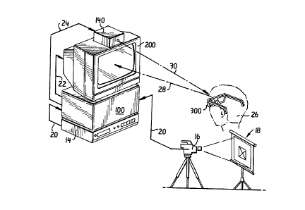
FlG. 1 is a simplified pictorial diagram of the invention in use;
FIG. 2 is a simplified block diagram of one embodiment of the present
invention;
PIG. 3 is a simplified block diagram of another embo-liment of tlle
present invention;
FIG. 4 illustrates a pictorial l~lciellt~tion of the normal sequence of 2D
video ~,ocsssed without CCinVC.~iOI~ to 3D;
FIG. 5 illustrates pictorially time multiplexing of the video to provide
separate ~h~alns for each eye;
SU~ST~TUTE St~EET (RU~E 2~)
2~77n~l
WO 95/15661 PCT/US9~/13286
11
FIG. 6 is a pictorial time-line illustration of the video frame ~q1-jciti-~n
in the storage buffer, the copy buffer, and multiplex display from the display
buffer with spatial offset, illcol~ol~ting the temporal display from frarne to
frame;
S FIG. 7 is a descli~lion of the ~log~ instruction set steps relating to
the plucess of FIG. 6;
FlGs. 8A, 8B, and 8C illustrate pictorially time multipiexing of the
video fields with dirreiing t~l"~ol~l offsets; and
FlG. 9 illustrates the state-space descriptions of the circular queue
stmcture for imple~ in~ the process of FIG. 7.
Detailed Descliplion of the Preferred Embodiments
The present three~ m~n~ional m~otlir~l im~in~ system invention may be
broadly understood by reference to FIGs. 1 and 2, in which a typical use of a
first embodiment of the invention lO is illustrated.
A video signal source 12 proYides a two--lim~cional (2D) analog output
signal Icplese~ g an image, especi~11y a sequence of images to the system.
Typical source apparatus incl~rle~ a video recorder 14 ~lo-lucillg an output
signal, a video camera 16 viewing a scene 18, including a lapar.,sco~,
endoscope, or other mPtli~l camera; a video scanner (not shown), or other
equivalent apparatus capable of producing a 2D source video signal 20. Note
that while the present discussion is directed primarily to analog video signals
in the NTSC or PAL formats, other signal formats, in~lu~in~ both analog and
digital may be used as is known to those persons having ordinary skill in the
art.
lhe analog video signal 20 is directed to a converter 100 for converting
the source video signal 20 to a field multiplexed three-dimencional sing1e-screen
display signal 22 for display on a monitor 200. Differing embo-limPn~s of the
present invention, directed to variations in tl1e configuration and operation ofconvertel 100 elements, are de~,clibed in greater detail hereinafter.
A blurry, s~- ."i~g1y out-of-focus, conventional 2D image is obse, ved by
those not wearing the special liquid-crystal light-con~ucting/shuttering viewingglasses 300. A switch (not shown) on the converter unit 100 allows the user
SU8STITUTE S~EET (RULE 2~)
WO 95/15661 PCT/US9-~113286
2~77~1 12
to bypass the 2D-3D conversion in order to view scene as ordinary 2D video
imagery. However, an obse. ~. r 26 wearing glasses 300 is enabled to view the
monitor 200 image as a ~im~ Pd three-di~Pnciorl~l (3D) image seen along a
viewing path 28 under control of a special liquid-cryshl device controller 140
which controls ~ ;n~ of the left eye and right eye lenses of the glasses 300,
and therefore the view of the obsel~.,., acco~di.,g to a signal 30 dil~ct._d to the
obse~ 26 and vi. ~ving glasses 300.
Glasses 300 are known to those ~Jc.~ons having ordinary skill in the art;
one source of liquid-crystal light~o.~ g glasses believed acceptable includes
10 the Stereographics C~ur~lion, of San Rafael, CA. U.S. Pat. No. 4,884,876
describes the opel~lion of glasses 300. The individual lenses may also be
mounted in other h~adge~r, such as a helmet or similar viewing equipment.
Turning now to the greater detail of converter 100 illustrated in a first
embodiment of the present invention 10 as shown in FlG. 2, an analog-to-digital
15 (A/D) video signal conversion circuit 110 is shown l~ceivhlg the source video signal 20. Either 8- or 24-bit A/D conversion can be used, with 24-bit
conversion providing 'true-color' digital leprese~ tion equivalent to the
lull-color displays offered in conventional analog television receivers. As video
technology develops, the petson having ordinary skill in the art will recognize
20 that the electronic modules described in Pig. 2 may exist in some in~t~nces as
stand-alone, colllllle.ci~lly available electronic products and in other instances
be implemented as custom circuitry.
l~igitized output from converter 110 on signal line 112 is directed to a
DeepVision signal ~locessor 120. A DeepVision Controller module, produced
25 under license from Delta System Design l.imited (London WC2, F.ngl~nf~)
available from AVS, a Division of Avesco, London, F.n~l~n-1, has been found
suitable in t;X~ P~ i use. This device is explained in greater detail in World
lntellectual Plopelty Or~ni7~tion publications WO 92/11735, WO 92/03021,
and WO 90/13848, which have been published under provisions of the Patent
30 Convention Treaty. The DeepVision processor 120 is a digital image
pluce~ lg circuit which colnl)lises image buffers for storage of ~ligiti7Pcl video
frames as well as circuitry to collvelt the input ~igiti7ed video signal on line112 into time displaced, image shifted video information. The timing signals
~TITUTE SHEET (RVLE 2B)
WO 95/15661 2 ~L 7 7 0 ~ 1 PCT/US91113286
13
necess~ry to ensure proper, s~l.chluniLed operation of the col~eller 110 may
be provided by speci~li7~d pro~ le timing chips such as Synchronous
Pulse Generators (SPG's) or by microprocessors.
A time-base coll~.,tor circuit 122 may be required in certain
S tombo~imPn~c in coo~l~liol~ with the DeepVision pr~ces;,or 120 for ~IF ~ ;n;l~g
various tirne relqtiol~ .s and e,~ n. . ~ certain time-based clock signals whichare required by the ~roce;,~or 120. A HOTRONICS, Campbell, California,
Model AP-41 time-base co,l-_clor has been used in the present illv~nlioll.
Functionally, the time-base col~clol provides frame le~ ion coll~,clion,
10 especially for VHS video signals. Input signals from the l~rocessor 120 are
received, line 114, l,locessed, and frame registration co~-~clion output signalsare commllnir~ec~ to the processor 120 on lhle 116. The DeepVision processor
120 output is provided on iine 118.
A field/frame multiplex video controller 130 serves as the digital
15 electronic interface and driver circuitry for the display monitor 200 via line 22.
The person having ordinary skill in the art will recognize that in some instances
this module may operate with video fields while in other inct~nres it may
operate with full video frames. The field/frame multiplex controller consists
of a video frame buffer which stores the digital video signals prior to their
20 read-out to the display monitor 200. The field/frame multiplex video controller
130 also generates as part of the video signal the timing signals on line 2
nece~ . y to drive display monitor 200 at double its normal vertical refresh rate
(e.g., 120 Hertz per second for NTSC video)~ Video controller 130 stores two
or more complete images for left and right ch~nnPl output in each standard
25 display interval. A Stereo Video Display Controller 140 (St~l.,o~ phics, San
Rafael, USA) connPcted as an emitter control output from the field mu!tiplex
video controller 130 receives a control signal on line 24~ The liquid-crystal
device controller 140 is an emitter device which in turn controls the
liquid-crystal lenses for the left eye/right eye shutter switching of the viewer30 glasses 300~
The field multiplexed video signals are output on signal line 22 to a
200 for viewing~ While various combinations of ho~i~ollt~l and vertical
n~ may be used ~cees!ir~lly with the present invention, typical scan rates
~TItUTE 6HEE~ (RULÉ 26~
WO 95/15661 PCT/US9 1113286
2~L7~g~l 14
of 120 Hertz vertical and 37.5 Khz which result in left- and right-ch~nn~l
outputs at 60 ffelds per secorid or 30 fMmes per second are believed useful. A
Sony multi-sync monitor, such as the Model 2036S or Model 2038, is believed
suitable for viewing the 3D images 5y~ . d from 2D images with the
present invention 10. A 20-inch (diagonal ~l-casu~ .,nl) l~lonil~)r 200 is
believed suitable for most i,~iluss~ m~mlf~ ing~ ll sealcll, and biomP~
uses, as in O~eL~ g theaters. A plurality of lllonilo~s 200 can be used. For
individual viewing, smaller, individual video displays may be used, while for
group viewing, larger monitors or projection viewers may be used, as known
to those persons having ordinary skill in the art.
Another embodiment 40 of the present three--~im~n~iQnal medic~l
im~ging system invention is shown in detail in FIG. 3, using a microcG~ ul~r
and digital im~ing processor to optimize the conversion process and improve
resolution of the displayed images. This system, which may be built around a
general-purpose small con-~ulcr or worl; ~l~tion, is capable of further
optirnization through software control.
A source 12 of 2D video irnage signals, especially a sequence of images,
is supplied to the system as with the first embodiment previously described.
Again, typical analog video image source apparatus includes a video recorder
14 producing an output signal, a video camera 16, or other equivalent apparatus
capable of producing a 2D source video signal 20. The analog video signal
may be provided in either the NTSC or PAL (or equivalent) formats; again,
other signal forrnats, including both analog and digital may be used as is known to those persons having ordinary skill in the art.
The analog video signal 20 is directed to a 2D-3D converter 400 for
converting the source video signal 20 to a time-multiplexed three-dimensional
single-screen display signal 22 for display on a monitor 200.
ln this second embodiment of the three-dimensional medical imaging
system 40, all-digital processing is applied to the ~igi~i7t-d 2D signal 20 in the
2D-3D cor~v1ller 400. The digital im~ging p locessor 402 is typically
programmable and may operate under local control with its own on-board
central processing unit (CPU), or alternatively under control of the host
computer 408. This architecture is generalized, and may be implemented by
~UBSTITUTE SHEET (RULE 26~
wo sstls661 ~ 1 7 7 ~ ~ 1 PCT/US94/13286
a variety of circuit modules as add-in circuitry to conventional micluco
or woll~sWion collll.ul~
The 2D analog videû signal 20 is ligiti7ed in high-resolution video A/D
converter ci~ illr 404 providing 24-bit color A;~i~i7~ion from NTSC, PAL,
S S-VHS, or Y/C com~ lc signal inputs. Applicants note that real-time color
space cc,~ ,o~l (RGB-HSI-YIQ) of the video signals may also be y~lro~ ed
in a suitably c.~ ed ~i~iti7er. Following COn~ iOIl in the ~lig;~i7~pr 404, the
digital video signal 406 is output from the (1i~iti7er
Digital video signal 406 is ~ocess,_d in a digital im~ging ~loce~or,
10 typically a l~lu~ nable digital im~in~ l)iucessor 402. For the present
illustrative emborlim~ , a Matrox C~., Montreal, C~n~ , Model lM-1280 or
equivalent image ~locessol is used, under control of a fast small conlL~uler,
which may be a ll.icr~cGll-pu~._r 408 of 32-bit or greater bus capacity, such asis provided with an lntel 486 or Feiltil~l.. series (or such equivalents as are
15 known to those l)el~olls having ordinary skill in the art) micluplocessor chip
from llul~ ous m~nnf~f-t-.le,~, The lM-1280 image ploces~ol can be supplied
on standard sized PC microco..-plller cards which co...~ ir~e with the CPU
of host micloco-l-~ut~r 408 via the mic~uco.npuler bus. When in operation, the
im~gin~ p~uccssor card itself performs instructions according to a program
20 instruction set 410 which can be read from the host computer data storage 412to memory 414 and stored locally. These instructions are e~ec--ted under local
control of the CPU resident on the image processor board. Instructions and
data on the board are tr~n~mitted along a high-bandwidth local bus. A 32-bit
wide or greater bus is preferred. The person having ordinary skill in the art
25 will recognize that other coln~ ni~ ions ch~nnPls may also be used with
a~,~.up.iate bus standards. Digitized signal 406 is con.. ~ic~t~d to an input to
the imaging ylOCeS~Ol 402. The ~j~iti7ed video ûutput on line 406 comprises
a stream of seyuential video frames of data.
Digital im~in~ ocessor 402 receiyes control input, and other signals
30 from the micloco,--~ 408 on signal lines 4i6, while comm--nic~ing cûntrol
output, and other sigMls to the microcomputer on signal lines 418. The stream
of sequential r~igi~i7e~ video frames received on signal line 406 is ylùcessed
under computer control to provide a le.llpol~lly- and spatially-offset series of
~U~STITUTE Sl~EET (RU~E 28)
WO 95/15661 PCT/US9~1/13286 ~
2~ 77~51 16
video frame images which are stored in a video display output buffer 420 prior
to display on video display monitor 200. One form of i,l,~ .lP~ ion the
software-based signal plucP~c~ utilizes a data structure known as a circular
queue and will be ~ ;1~ hereinafter. The frame image data is selectPcl from
5 among the data le."~ol~rily stored in the circular queue and provided as an
output on signal line 422 to the video frame buffer 420.
Also I~lUViliC~d (by im~ine l)luce~i,ol 402) are a device ccntroller signal
on signal line 424 for controlling the liquid-crystal device controller 140 which
co"l~)ls left~ye/right~ye ~ t h~ via liquid-crystal light control glasses 300,10 described above.
Microcolll~u~r 408 is conventionally equipped with memory 414,
storage 412 (which may be a disk drive), and input/output functions 426,
including a keyboard, and a local PC monitor 428. Provision is ordinarily
made for a program instruction set within the micluco",puter, where this data
15 set may reside in disk or other equivalent storage for long-term, ready
~ccecsibility. Data storage 412, which is in~n~ied to include long-term storage,either volatile or non-volatile or both, as known to those pel~olls having
ordinary skill in the art, co---~ .-ir~t~ ~ with the microco~,yul. r 408 along signal
lines 430 and Illcnlol~ 414 co------m-ir~Ps along line 432. Other
20 communication, including the human-m~rhinP interface is repre~ ted here by
l/O block 426, and specifically includes a keyboard (not shown) and a local
monitor 428 for operation of the micloco~ ,uLer 408.
At signal line 406 a 30 frames per second (Fps) stream (for NTSC
video) of sequential (~igiti7Pt~ video frames is output from the analog to digital
25 converter 404. For a conventional 2D display as illustrated graphir~lly in FlG.
4, a stream of input video frames Fl, F2, F3, ..., is received, stored in a
storage buffer 450, transferred to a display buffer 452, then ll con~,led from
digital to analog data prior to being sc~nnPd out to a monitor 200. The display
rate for NTSC video signals is 60 fields per second (fps), since each frame is
30 comprised of two alte",alill~ filelds. That is, `all the (e.g.) odd-numbered
horizontal trace lines forming a first image are comml-nir~Pd, then all the
even-numbered holi~o~ l trace lines are commnnic~tPd. The lines of the first
and second fields are interlaced in the display at 60 Hertz to provide the
S~JBSTmJTE SHEET fRl ~E 2~
WO 95/15661 2 ~ 7 7 ~) ~ 1 PCT/US94113286
17
complete high r~:~;olution frame, displayed at a 30-Hertz rate. Of course, the
PAL rates are 50 and 75 Hert_, le~ccli~. ly. The fields are simply sc~nnP~I out
on the monitor in se~ e from the display buffer.
High-~e-r ~ e video ~ are known which provide a capability
- 5 of CO~ .Ihlg i,lL~.lsced video signals to non-in~rl~re~i signals, using
"line-doubling" or othe~r coll~p~lable t~c~ s. The line-doubling technique
effectively doubles the frame rate of the video system, i.e., to ~0 Fps, rather
than 30 Fps. With these ~t~_llls full frames of image data are moved from the
storage buffer 450 to the display buffer 452, and after lcco"~e.~ion to analog
data are sc~nn~.~l out to a ~onil~,r.
The present h~velllioll utilizes a time-multiplexing display technique. In
the time multiplexing method of display applied to traditional stereo video
im~ging, there are two incoming video streams, one from each lens or camera
in the binnc~ r vision appaldtu~ and each lens or camera in the binoc--l~r vision
apparatus and each eye therefore r~ ce;~,cs one stream of video data. In time
multiplexed sy~ lllS, two fields or frames of video information are stored in the
display buffer and sc~ .ed out to the display, which is driven at twice its
normal refresh rate. Therefore in one scan interval, i.e., one field or frame
period, two fields or frames of video are sc~nnPcl out, one to each eye. These
systems require syl,cl~lonized shutter glasses to properly decode the displayed
video, e.g., so that the left eye always sees the first of the time multiplexed
images and the second eye sees the second image in each display interval. The
present invention also uses time multiplexing but in the present invention each
eye views its own copy of the single input video stream, as depicted graphicallyin FlG. 5, which is altered according to the 3D synthesis p~ocPccing metho~ls
of the present invention, i.~., spatially offset and temporally offset (i.e., time
delayed).
The basic pruce~ g mPthorls used to implement the syn~hPsi7pd 3D
stereoscopic video system will now be described by reference to a diagram
showing time multiplexing of the video (FlG. 5), a pictorial time-line diagram
(FIG. 6), a tabular listing of steps in the ploce~ p sequence (FlG. 7), and a
discussion of variations of the basic processin~ method Wh~ the time delay
SU~STlTUtE SHEEt (RULE 26~
WO 95/15661 PCT/US94113286
2 ~ 7 ~ 8
between the left eye stream and the right eye stream is varied, using a field-
multiplexing form of ~loce ~ (Fig.8).
The r ~n~ .P,~l elemPn~c required for this yroces~ g are illustrated in
FIG. 5, which shows an inp~ video stream of sequenti~l video frames, F1, F2,
S F3... and three s~ari5te image buffers, inr~ir~t~1 as storage buffer 450, copybuffer 454, and display buffer 452 through which the input video stream passes
in pl~dete".,ined order, and FIG. 6 le~l~3e,ll~ a time-line view of the
processing applied to the input se4uence of video frames. The "clock" which
regulates this ~ocessi.~ is derived from the timing of the input video signal,
I0 i.e., 30 Fps for NTSC video, or 1/30 second for each input video frame (25
Pps for PAL video, or 1125 second.for each PAL input video frame). It is
noted that, depPn-ling on the particular hardware electronics configuration (first
embo-limPnt) or software ~)lOCeSSil~g technique (second embodiment) employed,
the operations used to encode video data for 3D display and to format video
15 data for 3D display may use either video fields (1/2 frames) or full video
frames as the basic image entity upon which such proce~cl~g is ~ ro,lned. The
following elaboration of the fund~mPI f~l p,ocFssi-~g sequence employed for the
creation of sy,~ (l st~ OSCOpiC video im~ging applies equally to either field
or frame l,locessh~g.
Two f uul~.. P"lal operations are performed on the in~oming video data
in order to encode the res~lltin~ signals for ~-c;sel.lation of a 3D display. These
operations col..ylise a le...l)ol~l delay, typically of one frame be~ en the image
as seen by the left eye and that seen by the right eye, and a ho~i~ont~l spatialshift between the images seen by each eye. These basic operations proceed in
25 a fixed temporal sequenre as in(~ ted in FIG. 6. The sequence begins at time
T1 with the acquisition of the first frame of video data, F1 by storage buffer
450. At time T2, frame Fl is copied into copy buffer 454. The sequence
continues from T3 to T5 with the second frame F2 acquired and copied. At
time T5, while the next input video frame F3is being acquired, the previously
30 acquired and stored frames, i.e., Fl and F2 are sc~nn~d out of the display
buffer to a time-multiplexed display monitor 200. A spatial offset is applied tothe two images as they are displayed, so that they appear horizontally displacedone from the other. Viewed through synchronous ele.;lrollic glasses 300, the
8U~TlTUrE St~EET (RULE 26~
WO 95/15661 2 1 7 7 ~ ~ 1 PCT/US94/13286
19
left eye will see one image, i~e~, frame F1 with a negative spatial displ~c~P~mPrlt
and the right eye will see the other image, i.e., frame F2, with the opposite
spatial displac~-..r--l. This basic ~luccc~ing seqlle-~e is then repeated ad
i~fi~;l"........ .~
S The spatial ~lispl~re-.. ~ l b~h~e,~ each image in a displayed pair of
frames is approximately 0-2~% of the screen width (i.e., one I~Gf;~.o~ trace
line), and ~lcl~rably 10-20% of the screen width. A spatial dL,~lacc~ l of
about 15% of the screen width is p~ d, calibrated to the particular size of
the monitor being used~ The offset may be acco~ lished for the left eye
10 ~ se.ltation by removing the first pichlre elements at the begi~ hlg of a given
trace line and completing the line with black picture el~ n~ For right eye
yiese~ ion, the trace line is begun with the incoll,ol~tion of black picture
elements at the be~inning of the trace line and the ending picture cle,l,~l.ts are
removed~ The same number of picture elern~n~ are removed from each trace
15 line and for the frames for each l~ s~e~ e eye~ Similarly, the same number ofblack picture Cle~l~f nl.c are added to each trace line and for the frames for each
respective eye.
The time delay bet~,e.l the pair of video images displayed in each
display interval can be varied, as for example by a period equal to one field
20 delay period, two field delay periods (i~e~, one frame period) or three fielddelay periods (1 1/2 frame periods)~ Varying the image-pair delay period alters
the 3D effect in the view pl~i,ented the viewer wearing emitter-controlled
glasses 200~ A longer delay h~cl~ases the 3D depth effect, but may result in
certain illcon~:~lçnries in the perceived images, particularly where considerable
25 mûtion is present in the scene~ Alternatively, a shorter inter-image delay
reduces the depth effect, while providing a more consistent visual perception for
moving objects.
FIGs. 8A, 8B, and 8C illustrate scllPtn~tie~lly the technique employed
for providing time delays of equal to the period of 1, 2, or 3 fields by u~ili7inE
30 field-multiplexed procPssin~ and display~
When a series of frames F1, F2, P3, F4, ..., are received, FIG~ 8A,
each with two fields (lA, lB; 2A, 2B; 3A, 3B; 4A, 4B; ...;), cG.l~e.ler 100
(first embodiment) or the digital im~EinE processor 402, under computer
SUBSTlTUTE ~ET (RULE 26)
PCT/US9~/13286
control, must produce four sets of image data per frame as seen in FIG. 8A.
The i~lenliri~A~iQn scheme used herein is as follows: the field and frame
ide~ ion~ are to be read from left to right, then from top to bottom, within
a given frame. A first`~eld lA ~ se.-l~ a first field of the ~lrst frame (F1)
S from the left (L) eye stream, and a second field lB 1`~1~3~nlS the second field
of the first frame from the left eye stream. First and second ~field lA and lB
are also genel~t~_d for frame one (F1) for the right (R) eye. Similar fields aregene.~hd for each eye for each of the ~"ccceAing frames, frame Fl-P4. This
ese~ the field multiplexed video sl~ ls with a tirne delay equal to lf, or
10 one field, for each eye.
A spatial offset is also ge,lel~d for each field (lA, lB) of each frame
(F1-F4) for each eye stream. In FIG. 8A, this is .~p,~enled by a positive
symbol (+) or a negative symbol (-) suffix following the field identification
(e.g., lA+, lA- and lB+, lB-). Thus, the first field lA, offset horizontally,
15 is presented for the left eye, from the left eye offset, is ~-~senled for the right
eye. Next, the left and right eye second felds are pr- sel~trd. Frame two is
then displayed in this field multiplexed form. In sequenre the frame data of
frame 1 in FIG. 8A is read out to the viewer in order: lA+, lA-, lB+, lB-.
The ylc~e~ Ql~ of sl~cces~ive fields from each left-eye/right-eye stream
20 delayed by a period of lF (i.e., 2f) is illustrated in FIG. 8B. Again, the video
stream is divided, left eye, right eye, and the fields among the frames are timedelayed.
At a first time, field OA (which may be the prece(lin~ frame first field)
is displayed, ho,iLunlally displaced (i.e., OA+), for the left eye, then the first
25 field of the first new frame Fl is displayed, also horizontally offset in theopposite direction: lA-. Next, the preceding frame second field is displayed,
holi~ont~lly offset: OB+ for the left eye, then the second field of the first new
frame Fl is displayed, also horiLolllally offset in the opposite direction: lB-
A lF (2f) time delay is thus effected. In the next frame, first field lA+ is
30 p,esellled for the left eye, then field 2A- for the right eye, then field lB~ for
the left eye and field 2B- for the right eye and so on.
The p,~.e..~tion of s~cce~ e fields from each left-eye/right-eye stream
delayed by a period of 1.5F (i.e., 3f) is illustrated in FIG. 8C. Again, the
SllBSTlTUTE SHEET (Rl~LE 26~
~ wo 95/15661 2 i 7 7 0 5 1 PCT/USg4/13286
21
video stream is divided, left eye, right eye, and the fields among the frames
delayed. Field lA~ is displayed at a first time, holi~o,.~ally displaced, for the
left eye, then the second field of the second frame F2 is displayed for the right
eye, also ho,i~ tally offset in the o~osile d~ lioll: 2B-. Next, the first
frame second field is displayed for the left eye, holiL~l~lally offset: lB+, then
the first fteld of the third frame F3 is displayed for the right eye, also
hori~ lly offset in the opposite dil~ n: 3A-. A 1.5F (3f; time delay is
thus errc~t. d. In the next frame, first field 2A~ is p.e;,e.lt~ d for the left eye,
then 3B- for the right eye, then 2B ~ for the left eye and 4A- for the right eye,
10 and so on.
A "circular queue" data struct~re is one ~Llllclul~ for implel.le~ tion of
the 3D ~ ce;?sil-~ step; this data structure is particularly well suited to the
cu...~ r-based digital embodiment of the present invention as di~c~l~sed above,
because the rules go~e~ g operation of the circular queue may be implemented
15 entirely in software. It is convenient to use a "state-space" description for the
operation of the circular queue (FIG. 9).
The circular queue exists in memory (which may be separate in the
video frame buffer 420 or portions of the micloco...l,ul~r 408 memory 414) as
three image buffers. Por the present example, the circular queue will be
20 described as being implern~n~ed in hardware, e.g., as three distinct regions of
digital lllellloly allocated within the video frame buffer 420. Each image buffer
will have a "state" de~lned by two variables, x and y, in FlG. 9, where x
designates ~l.cl~er an image is present or not in the buffer and y desi~n~tes
whether a positive or negative spatial offset is applied to the irnage residing in
25 the buffer. An asterisk: "*" jntiir-~tPs an indete~nin~te state.
In operation, the states of each image buffer are updated upon each
clock cycle; the clock speed in this case is determin~d by the input video framerate, e.g, 30 frames per second (Pps) for a NTSC video signal. Since the
present invention uses a time-multiplexed display, the conte.,~ of two out of the
30 available three buffers are displayed in each clock period; this is in~lir~ed by
an arrow connPcting the two buffers being used for display in a given state.
At state 1, before data is received, the buffer col~ lts are, ~ eelively,
0*, 0*, and 0*. At staie 2, the buffer co-lle.lls are 10, 0*, and 0*. At state 3,
SUBSTlTUfE ~tlEET (RUl E 26)
W O 95/lS661 - PCTrUS94/13286
2 ~ 7 ~ 22
the buffer contents are 10, 11, and 0~. At state 4, the buffer contents are 10,
10, and 11. At state S, the buffer cont~ are 11, 10, and 10. At state 6, tlle
buffer conle.lls are 10, 11, and 10. Sul,se~ t states follow the 4, S, and 6
pattern.
S From FIG. 9 actual system display operation begins after two of the
image buffers are full (T1 through T4 in FIG. 7). The circular queue is fully
ope.~lio,lal after 4 clock cycles, i.e., in "state 4." From this pnint on, stable
ope.~tion l ruceeds through the r~t~etiti~re se~luence of states 4, 5, 6; 4, 5, 6; 4,
~, 6; ... etc.
~l~hough certain IJIL3eIIt1Y yl~fell~ d embodiments of the invention have
been de~ ed herein, it will be ap~a~ l to those pe.~olls having ordinary skill
in the art to which the invention pertains that variations and mo-lifir-~ions of the
desc~ilJed emborlimPn~ may be made without departing from the spirit and scope
of the invention. Accordingly, it is in~n-led that the invention be limited onlyto the extent required by the appellded claims and the applicable rules of law.
St~STlTUtE SHEET (RULE 26~