Language selection

Search

Patent 2177117 Summary

Third-party information liability

Some of the information on this Web page has been provided by external sources. The Government of Canada is not responsible for the accuracy, reliability or currency of the information supplied by external sources. Users wishing to rely upon this information should consult directly with the source of the information. Content provided by external sources is not subject to official languages, privacy and accessibility requirements.

Claims and Abstract availability

Any discrepancies in the text and image of the Claims and Abstract are due to differing posting times. Text of the Claims and Abstract are posted:

  • At the time the application is open to public inspection;
  • At the time of issue of the patent (grant).
(12) Patent: (11) CA 2177117
(54) English Title: DIFFUSER FOR COAL NOZZLE BURNER
(54) French Title: JET DIFFUSEUR POUR BRULEUR DE CHARBON
Status: Expired and beyond the Period of Reversal
Bibliographic Data
(51) International Patent Classification (IPC):
  • F23D 01/00 (2006.01)
(72) Inventors :
  • LAROSE, JEFFREY A. (United States of America)
(73) Owners :
  • THE BABCOCK & WILCOX COMPANY
(71) Applicants :
  • THE BABCOCK & WILCOX COMPANY (United States of America)
(74) Agent: SMART & BIGGAR LP
(74) Associate agent:
(45) Issued: 1999-03-30
(22) Filed Date: 1996-05-22
(41) Open to Public Inspection: 1996-11-24
Examination requested: 1996-05-22
Availability of licence: N/A
Dedicated to the Public: N/A
(25) Language of filing: English

Patent Cooperation Treaty (PCT): No

(30) Application Priority Data:
Application No. Country/Territory Date
08/448,206 (United States of America) 1995-05-23

Abstracts

English Abstract


A diffuser for a coal burner has a coal nozzle with an
axis and an inner surface. The diffuser comprises a
reducing area cone which has tapering upstream and
downstream ends, for positioning in a coal nozzle at the
coal nozzle axis. A frusto-conical shroud has a small
diameter upstream end and a large diameter downstream end,
positioned around the reducing area cone. A plurality of
support legs is connected to the reducing area cone and
extends radially outwardly through the shroud for
connecting to the coal nozzle. Each of the support legs is
inclined at an acute angle to the axis of the coal nozzle
for evenly spreading pulverized coal supplied through the
coal nozzle and past the diffuser.


French Abstract

Le diffuseur d'un brûleur au charbon est doté d'une busette à charbon possédant un axe et une surface interne. Le diffuseur comporte des extrémités coniques amont et aval destinées au positionnement à l'intérieur de la busette à charbon et dans l'axe de celle-ci. Une enveloppe frusto-conique présentant un faible diamètre amont et un grand diamètre aval est positionnée autour du cône de restriction. Une pluralité de pattes de support sont reliées au cône de restriction et se prolongent radialement vers l'extérieur et à travers l'enveloppe aux fins de fixation à la busette. Chacune des pattes de support définit un angle aigu par rapport à l'axe de la busette, pour assurer une distribution uniforme du charbon pulvérisé par la busette à charbon au-delà du diffuseur.

Claims

Note: Claims are shown in the official language in which they were submitted.

WHAT IS CLAIMED IS:
1. A diffuser for a coal burner having a coal nozzle with
a longitudinal axis and an inner surface, the diffuser
comprising:
a reducing area cone having tapering upstream and
downstream ends, for positioning in a coal nozzle at the
longitudinal axis;
a frusto-conical shroud having a small diameter
upstream end and a large diameter downstream end, positioned
around the reducing area cone; and
a plurality of support legs fixed rigidly to the
reducing area cone and extending radially outwardly through the
shroud for fastening to the coal nozzle, each of the support legs
being inclined at an acute angle to the longitudinal axis of the
coal nozzle for evenly spreading pulverized coal supplied through
the coal nozzle and past the diffuser.
2. A diffuser according to claim 1, wherein the acute
angle is approximately 10°.
3. A diffuser according to claim 2, including four support
legs fixed rigidly to the reducing area cone and equally spaced
around the longitudinal axis of the coal nozzle.

4. A diffuser according to claim 3, wherein each of the
legs is a flat plate.
5. A burner for burning particulate coal comprising:
means defining a windbox;
a coal nozzle extending through the windbox and
including a longitudinal axis;
a diffuser in the nozzle, the diffuser comprising a
reducing area cone having tapering upstream and downstream ends,
for positioning in a coal nozzle at the longitudinal axis;
a frusto-conical shroud having a small diameter
upstream end and a large diameter downstream end, positioned
around the reducing area cone; a plurality of support legs fixed
rigidly to the reducing area cone and extending radially
outwardly through the shroud for fastening to the coal nozzle,
each of the support legs being inclined at an acute angle to the
longitudinal axis of the coal nozzle for evenly spreading
pulverized coal supplied through the coal nozzle and past the
diffuser;
means defining inner and outer secondary air zones
around an outlet end of the coal nozzle for supplying secondary
air from the windbox to an area around an outlet end of the
nozzle; and

means for providing particulate coal and primary air to
the coal nozzle.
6. A burner according to claim 5, including spin vanes in
each of the inner and outer secondary air zones.
7. A burner according to claim 6, wherein the acute angle
is approximately 10°.
8. A burner according to claim 7, including four support
legs fixed rigidly to the reducing area cone and equally spaced
around the longitudinal axis of the coal nozzle.
9. A burner according to claim 8, wherein each of the legs
is a flat plate.

Description

Note: Descriptions are shown in the official language in which they were submitted.


21771 17
CA8E 5643
Dll ~ U~i~;~ FOR CO~l, NOZZLE BtURNER
:.
BAC~KGROUND OF TElF, INV~ ON
. F~ELD OF T~E INVb,~ lON
Conical diffusers are routinely used in burner coal
nozzles to distribute the coal around the peripheral.
5 Previous experience suggests that if the coal particles can
be evenly distributed around the inside surface of the coal
pipe, the~ combustion f~ff;l ;~nry will improve. This
t translate5 into lower llnhllrnt~d carbon losses and
potf~n~iAlly lower nitrous oxide t~m;~ nA.
0 2. DES(,~~ .OFTlll I~F~ATFI'ART
: U.S. Pate~t 4,380,202 illustrates a mixer for a dual
register burner with a diffuser int lll~;n~ a reducing area
cone, i~1t~nt;f;,~ as an ~toblong-diamond ~haped plug", and
frusto-conical shroud co-axially ,ju, L~,u-.ding the plug.
15 Plug supports rigidly fix the plug to the inside of the
shroud. The plug supports are shaped to m;~;m; 7~ the flow
resistance to the air entrained pulverized fuel. No
further disclosure is provided f-~-nt-t~rn;"s the number o~
plug supports and, in the illustration of the reference,
20 only two supports are shown, which are parallel to the axis
o~ the dif ~user .

21 77t t7
~ASE 5643
U.S. Patent 4,479,442 is directed to a venturi nozzle
for pulverized coal including a divergent flow spreader
that is provided with plural swirl vanes.
U. S . Patent 2, 912, 942 shows a pulverized fuel burner
with vanes circumferentially spaced apart. They are
triangular-shaped in cross-section and their apexes face
the burner axis. The vanes are located on the inner
surface of a frusto-conical shroud.
SUl~AR~ OF TIIE INVENT~ON
The invention is drawn to a support leg arrangement
for a conical diffuser designed to improve the distribution
of pulverized coal around the periphery of a coal nozzle in
a coal burner. According to the invention and a reducing
area cone is designed with four (4) support legs equally
~3paced a~ound the reducing area cone, and between the cone
and a frusto-conical shroud. All four legs are angled at
an acute angle to the burner axis, ~rec;f;--Ally ten
degrees .
U6e of four angled support legs makes the diffuser
unique relative to previous designs which used two support
lega that are parallel to the nozzle axis since a highly
advantageous and unexpected f low pattern is created .

21771 17
CA6E 5643
Accordingly, an object of the present invention i8 to
provide a diffuser for a coal burner having a coal nozzle
with an axis and an iImer surface, the diffuser comprising:
a reducing area cone having tapering upstream and
5 downstream ends, for positioning in a coal nozzle at the
coal nozzle axis; a frusto-conical shroud having a small
.i; i -tPr upstream end and a large diameter downstream end,
positioned around the reducing area cone; and a plurality
of support legs r~nnPctPcl to the reducing area eone and
10 P~ nr1;n~ radially outwardly through the shroud for
connecting to the coal nozzle, each of the support legs
being ; nrl; nPd at an aeute angle to the axis of the coal
nozzle for evenly spreading pulverized eoal supplied
through the eoal nozzle and pagt the diffuser.
A further objeet of the invention is to utilize four
support legs which are each in the form of flat plates, and
are each inrl ;nP(~ at approximately 10 to the axis of the
eoal nozzle.
A further obj eet of the invention is to provide an
20 improved diffuser for a coal nozzle which is simple in
design, rugged in construction and economical to
.--nl~fi~rtllre .
The various features of novelty which characterize the
invention are pointed out with partieularity in the elaims

~771 17
CASE 5643
annexed to and forming a part of this disclosure. For a
better understanding of the invention, its operating
advantages and speci~ic objects attained by its uses,
reference is made to the ~c~ ~ ying descriptive matter in
5 which a preferred embodiment of the invention is
illustrated .
~R~,F D1;'.~ K 1~ llON OF 1~, DRAWINGS
In the drawings:
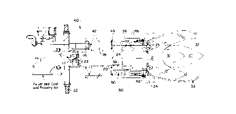
o Fig. 1 i8 a axial gectional view of a coal burner
incorporating the dif fuser of the present
invention;
Fig. 2 is a rear elevational view of the diffuser of the
present invention; and
5 Fig. 3 is a sectional view talcen along line 3-3 of Fig.
2.
DESCRTPT~ON OF ~ PRh~ RR~n EMBOD~MF,l~
A typical burner with the conical diffu~er of the
20 invention is shown in Fig. 1. ~he diffuser 10 is located
near the exit end 12 of an upstream pipe elbow 14, to
redistribute the coal. A reducing area cone or frusto-
conical shroud 16 traps some of the coal and pushed it

` 2177117
CASE 5643
toward the inner surface 18 of a coal nozzle 20. The
diffuser of the inve~tion ~ nt~;n~ four support legs 22
which are at an angle to the nozzle axis 24.
The conical dif fuser of the invention has been
5 developed to improve the coal distribution around the
peripheral of the coal nozzle. The new conical diffuser 10
retains the reducing area cone 11 of prior designs, but
adds additional support legs. All four of the support legs
22 are angled at ten degree8; see Fig. 2. The use of four
10 angled support legs makes this diffuser unique from any
previous designs.
This arrangement has the advantages of a better coal
distribution, and is more tolerant of coal roping upstream
of the coal nozzles.
The new diffuser was quantitatively tested by the
inventor using an exiating coal pipe dLLdl~, t with a
typical coal to air loading . The air velocity prof ile at
the end of the burner nozzle for the inventive diffuser
showed substantial; _ vv over the prior art in evenly
20 distributing coal. The coal particle velocity through the
diffuser to the e~d of the nozzle waa also improved. The
new design has a much better distribution around the
peripheral with a lower velocity core in the center than
the prior art . The new design added one- third of an inch

21771 17
CA6E 5643
water gage draf t 1088 in achieving the improved
distribution for this aLLcUly and loading.
Coal roping occurs in the transport process of the
part; r~l7 ~te (coal) being carried by the air. Particulate
5 is dragged by the flowing medium causing it to lag in
changes in flow pattern3 due to piping. This allows the
coal to become concentrated, and travel in a small portion
of the piping cross section. This ~rope" of coal travels
through the piping to the burner nozzle. The diffuser of-
10 the invention with its four angled support legs helps tobreak the c~nr~ntrated coal rope which provides a better
coal distribution.
These i _ uv~ t8 will show up at coal fired boilers
by reducing the unburn carbon losses, and lowering the
15 nitrous oxide emissions.
Returning to Fig. 1, the burner into which the
diffuser 10 of the present invention is installed, is
generally designated 40 and is mounted in a windbox 30
defined between an inner wall 32 and an outer wall 34 of a
20 furnace. Elbow 14 is rrnn~ctF~7 to a source of primary air
and pulverized or otherwise particulate coal. The coal is
supplied along coal nozzle 20 and creates a flame having
different portions labeled A, B, C and D in Fig. 1.
An annular i~ner secondary air space 36 is defined

2~771 17
CASE 5643
around the outlet or downstream end of coal nozzle 20, and
supplies s~ n~l~ry air around the base of the flame to form
high temperature-fuel rich dev~ ;l;7~ n zone A. At 35,
some of the inner secondary air i8 recirculated to the base
of the flame.
An outer seC~n~l~ry air zone 38 is defined around the
inner zone for supplying an outer secondary air mixture 39
which mixes with the flame to form reducing species in zone
B, NO" ~' , ~ ition in zone C and char ~ ; n~ in zone
D. A slide damper 42 adjusts the air flow to the secondary
zones which is measured by an air measuring device 44.
Adjustable spin vanes 46 are provided in the inner and
outer secondary air zones. An air separation plate 48 is
provided between the inner and outer secondary air zones
and also at the outlet end of coal nozzle 20 for shaping
the flame an directing the air flows. Spin vanes 50 may
also be provided in the U~ L~CIIII end of the outer secondary
air zone for further modifying the characteristics of the
f lame .
While a specific ~mhori; of the invention has been
shown and described in detail to illustrate the application
of the pr; n(~; rl~ of the invention, it will be understood
that the invention may be embodied otherwise without
departing from such pr; nt~; rl~

Representative Drawing
A single figure which represents the drawing illustrating the invention.
Administrative Status

2024-08-01:As part of the Next Generation Patents (NGP) transition, the Canadian Patents Database (CPD) now contains a more detailed Event History, which replicates the Event Log of our new back-office solution.

Please note that "Inactive:" events refers to events no longer in use in our new back-office solution.

For a clearer understanding of the status of the application/patent presented on this page, the site Disclaimer , as well as the definitions for Patent , Event History , Maintenance Fee  and Payment History  should be consulted.

Event History

Description Date
Time Limit for Reversal Expired 2000-05-23
Letter Sent 1999-05-25
Grant by Issuance 1999-03-30
Inactive: Final fee received 1998-12-15
Pre-grant 1998-12-15
Notice of Allowance is Issued 1998-09-28
Letter Sent 1998-09-28
Inactive: Status info is complete as of Log entry date 1998-09-23
Inactive: Application prosecuted on TS as of Log entry date 1998-09-23
Inactive: Approved for allowance (AFA) 1998-08-26
Application Published (Open to Public Inspection) 1996-11-24
Request for Examination Requirements Determined Compliant 1996-05-22
All Requirements for Examination Determined Compliant 1996-05-22

Abandonment History

There is no abandonment history.

Maintenance Fee

The last payment was received on 1998-05-01

Note : If the full payment has not been received on or before the date indicated, a further fee may be required which may be one of the following

  • the reinstatement fee;
  • the late payment fee; or
  • additional fee to reverse deemed expiry.

Patent fees are adjusted on the 1st of January every year. The amounts above are the current amounts if received by December 31 of the current year.
Please refer to the CIPO Patent Fees web page to see all current fee amounts.

Fee History

Fee Type Anniversary Year Due Date Paid Date
MF (application, 2nd anniv.) - standard 02 1998-05-22 1998-05-01
Final fee - standard 1998-12-15
Owners on Record

Note: Records showing the ownership history in alphabetical order.

Current Owners on Record
THE BABCOCK & WILCOX COMPANY
Past Owners on Record
JEFFREY A. LAROSE
Past Owners that do not appear in the "Owners on Record" listing will appear in other documentation within the application.
Documents

To view selected files, please enter reCAPTCHA code :


To view images, click a link in the Document Description column. To download the documents, select one or more checkboxes in the first column and then click the "Download Selected in PDF format (Zip Archive)" or the "Download Selected as Single PDF" button.

List of published and non-published patent-specific documents on the CPD .

If you have any difficulty accessing content, you can call the Client Service Centre at 1-866-997-1936 or send them an e-mail at CIPO Client Service Centre.


Document
Description 
Date
(yyyy-mm-dd) 
Number of pages   Size of Image (KB) 
Representative drawing 1999-03-21 1 11
Description 1996-09-05 7 213
Claims 1996-09-05 3 72
Abstract 1996-09-05 1 20
Drawings 1996-09-05 2 45
Claims 1998-07-21 3 68
Drawings 1998-07-21 2 43
Reminder of maintenance fee due 1998-01-25 1 111
Commissioner's Notice - Application Found Allowable 1998-09-27 1 163
Maintenance Fee Notice 1999-06-21 1 179
Fees 1998-04-30 1 36
Correspondence 1998-12-14 1 33
Correspondence 1997-01-08 1 29
Correspondence 1996-05-21 1 28
Correspondence 1996-08-08 1 35