Sélection de la langue

Search

Sommaire du brevet 2177117 

Énoncé de désistement de responsabilité concernant l'information provenant de tiers

Une partie des informations de ce site Web a été fournie par des sources externes. Le gouvernement du Canada n'assume aucune responsabilité concernant la précision, l'actualité ou la fiabilité des informations fournies par les sources externes. Les utilisateurs qui désirent employer cette information devraient consulter directement la source des informations. Le contenu fourni par les sources externes n'est pas assujetti aux exigences sur les langues officielles, la protection des renseignements personnels et l'accessibilité.

Disponibilité de l'Abrégé et des Revendications

L'apparition de différences dans le texte et l'image des Revendications et de l'Abrégé dépend du moment auquel le document est publié. Les textes des Revendications et de l'Abrégé sont affichés :

  • lorsque la demande peut être examinée par le public;
  • lorsque le brevet est émis (délivrance).
(12) Brevet: (11) CA 2177117
(54) Titre français: JET DIFFUSEUR POUR BRULEUR DE CHARBON
(54) Titre anglais: DIFFUSER FOR COAL NOZZLE BURNER
Statut: Périmé et au-delà du délai pour l’annulation
Données bibliographiques
(51) Classification internationale des brevets (CIB):
  • F23D 01/00 (2006.01)
(72) Inventeurs :
  • LAROSE, JEFFREY A. (Etats-Unis d'Amérique)
(73) Titulaires :
  • THE BABCOCK & WILCOX COMPANY
(71) Demandeurs :
  • THE BABCOCK & WILCOX COMPANY (Etats-Unis d'Amérique)
(74) Agent: SMART & BIGGAR LP
(74) Co-agent:
(45) Délivré: 1999-03-30
(22) Date de dépôt: 1996-05-22
(41) Mise à la disponibilité du public: 1996-11-24
Requête d'examen: 1996-05-22
Licence disponible: S.O.
Cédé au domaine public: S.O.
(25) Langue des documents déposés: Anglais

Traité de coopération en matière de brevets (PCT): Non

(30) Données de priorité de la demande:
Numéro de la demande Pays / territoire Date
08/448,206 (Etats-Unis d'Amérique) 1995-05-23

Abrégés

Abrégé français

Le diffuseur d'un brûleur au charbon est doté d'une busette à charbon possédant un axe et une surface interne. Le diffuseur comporte des extrémités coniques amont et aval destinées au positionnement à l'intérieur de la busette à charbon et dans l'axe de celle-ci. Une enveloppe frusto-conique présentant un faible diamètre amont et un grand diamètre aval est positionnée autour du cône de restriction. Une pluralité de pattes de support sont reliées au cône de restriction et se prolongent radialement vers l'extérieur et à travers l'enveloppe aux fins de fixation à la busette. Chacune des pattes de support définit un angle aigu par rapport à l'axe de la busette, pour assurer une distribution uniforme du charbon pulvérisé par la busette à charbon au-delà du diffuseur.


Abrégé anglais


A diffuser for a coal burner has a coal nozzle with an
axis and an inner surface. The diffuser comprises a
reducing area cone which has tapering upstream and
downstream ends, for positioning in a coal nozzle at the
coal nozzle axis. A frusto-conical shroud has a small
diameter upstream end and a large diameter downstream end,
positioned around the reducing area cone. A plurality of
support legs is connected to the reducing area cone and
extends radially outwardly through the shroud for
connecting to the coal nozzle. Each of the support legs is
inclined at an acute angle to the axis of the coal nozzle
for evenly spreading pulverized coal supplied through the
coal nozzle and past the diffuser.

Revendications

Note : Les revendications sont présentées dans la langue officielle dans laquelle elles ont été soumises.


WHAT IS CLAIMED IS:
1. A diffuser for a coal burner having a coal nozzle with
a longitudinal axis and an inner surface, the diffuser
comprising:
a reducing area cone having tapering upstream and
downstream ends, for positioning in a coal nozzle at the
longitudinal axis;
a frusto-conical shroud having a small diameter
upstream end and a large diameter downstream end, positioned
around the reducing area cone; and
a plurality of support legs fixed rigidly to the
reducing area cone and extending radially outwardly through the
shroud for fastening to the coal nozzle, each of the support legs
being inclined at an acute angle to the longitudinal axis of the
coal nozzle for evenly spreading pulverized coal supplied through
the coal nozzle and past the diffuser.
2. A diffuser according to claim 1, wherein the acute
angle is approximately 10°.
3. A diffuser according to claim 2, including four support
legs fixed rigidly to the reducing area cone and equally spaced
around the longitudinal axis of the coal nozzle.

4. A diffuser according to claim 3, wherein each of the
legs is a flat plate.
5. A burner for burning particulate coal comprising:
means defining a windbox;
a coal nozzle extending through the windbox and
including a longitudinal axis;
a diffuser in the nozzle, the diffuser comprising a
reducing area cone having tapering upstream and downstream ends,
for positioning in a coal nozzle at the longitudinal axis;
a frusto-conical shroud having a small diameter
upstream end and a large diameter downstream end, positioned
around the reducing area cone; a plurality of support legs fixed
rigidly to the reducing area cone and extending radially
outwardly through the shroud for fastening to the coal nozzle,
each of the support legs being inclined at an acute angle to the
longitudinal axis of the coal nozzle for evenly spreading
pulverized coal supplied through the coal nozzle and past the
diffuser;
means defining inner and outer secondary air zones
around an outlet end of the coal nozzle for supplying secondary
air from the windbox to an area around an outlet end of the
nozzle; and

means for providing particulate coal and primary air to
the coal nozzle.
6. A burner according to claim 5, including spin vanes in
each of the inner and outer secondary air zones.
7. A burner according to claim 6, wherein the acute angle
is approximately 10°.
8. A burner according to claim 7, including four support
legs fixed rigidly to the reducing area cone and equally spaced
around the longitudinal axis of the coal nozzle.
9. A burner according to claim 8, wherein each of the legs
is a flat plate.

Description

Note : Les descriptions sont présentées dans la langue officielle dans laquelle elles ont été soumises.

21771 17
CA8E 5643
Dll ~ U~i~;~ FOR CO~l, NOZZLE BtURNER
:.
BAC~KGROUND OF TElF, INV~ ON
. F~ELD OF T~E INVb,~ lON
Conical diffusers are routinely used in burner coal
nozzles to distribute the coal around the peripheral.
5 Previous experience suggests that if the coal particles can
be evenly distributed around the inside surface of the coal
pipe, the~ combustion f~ff;l ;~nry will improve. This
t translate5 into lower llnhllrnt~d carbon losses and
potf~n~iAlly lower nitrous oxide t~m;~ nA.
0 2. DES(,~~ .OFTlll I~F~ATFI'ART
: U.S. Pate~t 4,380,202 illustrates a mixer for a dual
register burner with a diffuser int lll~;n~ a reducing area
cone, i~1t~nt;f;,~ as an ~toblong-diamond ~haped plug", and
frusto-conical shroud co-axially ,ju, L~,u-.ding the plug.
15 Plug supports rigidly fix the plug to the inside of the
shroud. The plug supports are shaped to m;~;m; 7~ the flow
resistance to the air entrained pulverized fuel. No
further disclosure is provided f-~-nt-t~rn;"s the number o~
plug supports and, in the illustration of the reference,
20 only two supports are shown, which are parallel to the axis
o~ the dif ~user .

21 77t t7
~ASE 5643
U.S. Patent 4,479,442 is directed to a venturi nozzle
for pulverized coal including a divergent flow spreader
that is provided with plural swirl vanes.
U. S . Patent 2, 912, 942 shows a pulverized fuel burner
with vanes circumferentially spaced apart. They are
triangular-shaped in cross-section and their apexes face
the burner axis. The vanes are located on the inner
surface of a frusto-conical shroud.
SUl~AR~ OF TIIE INVENT~ON
The invention is drawn to a support leg arrangement
for a conical diffuser designed to improve the distribution
of pulverized coal around the periphery of a coal nozzle in
a coal burner. According to the invention and a reducing
area cone is designed with four (4) support legs equally
~3paced a~ound the reducing area cone, and between the cone
and a frusto-conical shroud. All four legs are angled at
an acute angle to the burner axis, ~rec;f;--Ally ten
degrees .
U6e of four angled support legs makes the diffuser
unique relative to previous designs which used two support
lega that are parallel to the nozzle axis since a highly
advantageous and unexpected f low pattern is created .

21771 17
CA6E 5643
Accordingly, an object of the present invention i8 to
provide a diffuser for a coal burner having a coal nozzle
with an axis and an iImer surface, the diffuser comprising:
a reducing area cone having tapering upstream and
5 downstream ends, for positioning in a coal nozzle at the
coal nozzle axis; a frusto-conical shroud having a small
.i; i -tPr upstream end and a large diameter downstream end,
positioned around the reducing area cone; and a plurality
of support legs r~nnPctPcl to the reducing area eone and
10 P~ nr1;n~ radially outwardly through the shroud for
connecting to the coal nozzle, each of the support legs
being ; nrl; nPd at an aeute angle to the axis of the coal
nozzle for evenly spreading pulverized eoal supplied
through the eoal nozzle and pagt the diffuser.
A further objeet of the invention is to utilize four
support legs which are each in the form of flat plates, and
are each inrl ;nP(~ at approximately 10 to the axis of the
eoal nozzle.
A further obj eet of the invention is to provide an
20 improved diffuser for a coal nozzle which is simple in
design, rugged in construction and economical to
.--nl~fi~rtllre .
The various features of novelty which characterize the
invention are pointed out with partieularity in the elaims

~771 17
CASE 5643
annexed to and forming a part of this disclosure. For a
better understanding of the invention, its operating
advantages and speci~ic objects attained by its uses,
reference is made to the ~c~ ~ ying descriptive matter in
5 which a preferred embodiment of the invention is
illustrated .
~R~,F D1;'.~ K 1~ llON OF 1~, DRAWINGS
In the drawings:
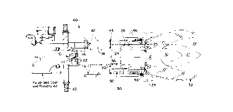
o Fig. 1 i8 a axial gectional view of a coal burner
incorporating the dif fuser of the present
invention;
Fig. 2 is a rear elevational view of the diffuser of the
present invention; and
5 Fig. 3 is a sectional view talcen along line 3-3 of Fig.
2.
DESCRTPT~ON OF ~ PRh~ RR~n EMBOD~MF,l~
A typical burner with the conical diffu~er of the
20 invention is shown in Fig. 1. ~he diffuser 10 is located
near the exit end 12 of an upstream pipe elbow 14, to
redistribute the coal. A reducing area cone or frusto-
conical shroud 16 traps some of the coal and pushed it

` 2177117
CASE 5643
toward the inner surface 18 of a coal nozzle 20. The
diffuser of the inve~tion ~ nt~;n~ four support legs 22
which are at an angle to the nozzle axis 24.
The conical dif fuser of the invention has been
5 developed to improve the coal distribution around the
peripheral of the coal nozzle. The new conical diffuser 10
retains the reducing area cone 11 of prior designs, but
adds additional support legs. All four of the support legs
22 are angled at ten degree8; see Fig. 2. The use of four
10 angled support legs makes this diffuser unique from any
previous designs.
This arrangement has the advantages of a better coal
distribution, and is more tolerant of coal roping upstream
of the coal nozzles.
The new diffuser was quantitatively tested by the
inventor using an exiating coal pipe dLLdl~, t with a
typical coal to air loading . The air velocity prof ile at
the end of the burner nozzle for the inventive diffuser
showed substantial; _ vv over the prior art in evenly
20 distributing coal. The coal particle velocity through the
diffuser to the e~d of the nozzle waa also improved. The
new design has a much better distribution around the
peripheral with a lower velocity core in the center than
the prior art . The new design added one- third of an inch

21771 17
CA6E 5643
water gage draf t 1088 in achieving the improved
distribution for this aLLcUly and loading.
Coal roping occurs in the transport process of the
part; r~l7 ~te (coal) being carried by the air. Particulate
5 is dragged by the flowing medium causing it to lag in
changes in flow pattern3 due to piping. This allows the
coal to become concentrated, and travel in a small portion
of the piping cross section. This ~rope" of coal travels
through the piping to the burner nozzle. The diffuser of-
10 the invention with its four angled support legs helps tobreak the c~nr~ntrated coal rope which provides a better
coal distribution.
These i _ uv~ t8 will show up at coal fired boilers
by reducing the unburn carbon losses, and lowering the
15 nitrous oxide emissions.
Returning to Fig. 1, the burner into which the
diffuser 10 of the present invention is installed, is
generally designated 40 and is mounted in a windbox 30
defined between an inner wall 32 and an outer wall 34 of a
20 furnace. Elbow 14 is rrnn~ctF~7 to a source of primary air
and pulverized or otherwise particulate coal. The coal is
supplied along coal nozzle 20 and creates a flame having
different portions labeled A, B, C and D in Fig. 1.
An annular i~ner secondary air space 36 is defined

2~771 17
CASE 5643
around the outlet or downstream end of coal nozzle 20, and
supplies s~ n~l~ry air around the base of the flame to form
high temperature-fuel rich dev~ ;l;7~ n zone A. At 35,
some of the inner secondary air i8 recirculated to the base
of the flame.
An outer seC~n~l~ry air zone 38 is defined around the
inner zone for supplying an outer secondary air mixture 39
which mixes with the flame to form reducing species in zone
B, NO" ~' , ~ ition in zone C and char ~ ; n~ in zone
D. A slide damper 42 adjusts the air flow to the secondary
zones which is measured by an air measuring device 44.
Adjustable spin vanes 46 are provided in the inner and
outer secondary air zones. An air separation plate 48 is
provided between the inner and outer secondary air zones
and also at the outlet end of coal nozzle 20 for shaping
the flame an directing the air flows. Spin vanes 50 may
also be provided in the U~ L~CIIII end of the outer secondary
air zone for further modifying the characteristics of the
f lame .
While a specific ~mhori; of the invention has been
shown and described in detail to illustrate the application
of the pr; n(~; rl~ of the invention, it will be understood
that the invention may be embodied otherwise without
departing from such pr; nt~; rl~

Dessin représentatif
Une figure unique qui représente un dessin illustrant l'invention.
États administratifs

2024-08-01 : Dans le cadre de la transition vers les Brevets de nouvelle génération (BNG), la base de données sur les brevets canadiens (BDBC) contient désormais un Historique d'événement plus détaillé, qui reproduit le Journal des événements de notre nouvelle solution interne.

Veuillez noter que les événements débutant par « Inactive : » se réfèrent à des événements qui ne sont plus utilisés dans notre nouvelle solution interne.

Pour une meilleure compréhension de l'état de la demande ou brevet qui figure sur cette page, la rubrique Mise en garde , et les descriptions de Brevet , Historique d'événement , Taxes périodiques et Historique des paiements devraient être consultées.

Historique d'événement

Description Date
Le délai pour l'annulation est expiré 2000-05-23
Lettre envoyée 1999-05-25
Accordé par délivrance 1999-03-30
Inactive : Taxe finale reçue 1998-12-15
Préoctroi 1998-12-15
Un avis d'acceptation est envoyé 1998-09-28
Lettre envoyée 1998-09-28
Inactive : Renseign. sur l'état - Complets dès date d'ent. journ. 1998-09-23
Inactive : Dem. traitée sur TS dès date d'ent. journal 1998-09-23
Inactive : Approuvée aux fins d'acceptation (AFA) 1998-08-26
Demande publiée (accessible au public) 1996-11-24
Exigences pour une requête d'examen - jugée conforme 1996-05-22
Toutes les exigences pour l'examen - jugée conforme 1996-05-22

Historique d'abandonnement

Il n'y a pas d'historique d'abandonnement

Taxes périodiques

Le dernier paiement a été reçu le 1998-05-01

Avis : Si le paiement en totalité n'a pas été reçu au plus tard à la date indiquée, une taxe supplémentaire peut être imposée, soit une des taxes suivantes :

  • taxe de rétablissement ;
  • taxe pour paiement en souffrance ; ou
  • taxe additionnelle pour le renversement d'une péremption réputée.

Les taxes sur les brevets sont ajustées au 1er janvier de chaque année. Les montants ci-dessus sont les montants actuels s'ils sont reçus au plus tard le 31 décembre de l'année en cours.
Veuillez vous référer à la page web des taxes sur les brevets de l'OPIC pour voir tous les montants actuels des taxes.

Historique des taxes

Type de taxes Anniversaire Échéance Date payée
TM (demande, 2e anniv.) - générale 02 1998-05-22 1998-05-01
Taxe finale - générale 1998-12-15
Titulaires au dossier

Les titulaires actuels et antérieures au dossier sont affichés en ordre alphabétique.

Titulaires actuels au dossier
THE BABCOCK & WILCOX COMPANY
Titulaires antérieures au dossier
JEFFREY A. LAROSE
Les propriétaires antérieurs qui ne figurent pas dans la liste des « Propriétaires au dossier » apparaîtront dans d'autres documents au dossier.
Documents

Pour visionner les fichiers sélectionnés, entrer le code reCAPTCHA :


Pour visualiser une image, cliquer sur un lien dans la colonne description du document. Pour télécharger l'image (les images), cliquer l'une ou plusieurs cases à cocher dans la première colonne et ensuite cliquer sur le bouton "Télécharger sélection en format PDF (archive Zip)" ou le bouton "Télécharger sélection (en un fichier PDF fusionné)".

Liste des documents de brevet publiés et non publiés sur la BDBC .

Si vous avez des difficultés à accéder au contenu, veuillez communiquer avec le Centre de services à la clientèle au 1-866-997-1936, ou envoyer un courriel au Centre de service à la clientèle de l'OPIC.


Description du
Document 
Date
(aaaa-mm-jj) 
Nombre de pages   Taille de l'image (Ko) 
Dessin représentatif 1999-03-21 1 11
Description 1996-09-05 7 213
Revendications 1996-09-05 3 72
Abrégé 1996-09-05 1 20
Dessins 1996-09-05 2 45
Revendications 1998-07-21 3 68
Dessins 1998-07-21 2 43
Rappel de taxe de maintien due 1998-01-25 1 111
Avis du commissaire - Demande jugée acceptable 1998-09-27 1 163
Avis concernant la taxe de maintien 1999-06-21 1 179
Taxes 1998-04-30 1 36
Correspondance 1998-12-14 1 33
Correspondance 1997-01-08 1 29
Correspondance 1996-05-21 1 28
Correspondance 1996-08-08 1 35