Note: Descriptions are shown in the official language in which they were submitted.
CA 02177342 2006-O1-25
TORSIONALLY RESILIENT DRIVER ROLL FOR ROLLED STRIP
BACKGROUND OF THE INVENTION
1. Field of the Invention
The present invention relates to a driver for rolled
strip including a first roll which is mounted so as to be
essentially stationary and a second roll which is adjustable
relative to the first roll. The second roll is supported in a
swivel frame which is adjustable by means of a pressure
medium cylinder. The swivel frame is composed of two
oppositely located links which are connected in the area of
their common swivelling axis by a base which is supported on
both sides thereof in the driver frame.
2. Description of the Related Art
Drivers of the above-described type have a base which
rigidly connects the links to one another. In order to be
able to influence the characteristic curve of the tensile
force exerted by driving, the rolls have been mounted in
chocks which are constructed so as to be adjustable by
applying a force. Adjustably constructed stops have also
already been provided for limiting the movement of the links.
However, the adjusting units required for this purpose are
very cumbersome because they are subjected to high bearing
forces and the adjusting devices which may be desired for
2
_ 2177342
the bearing forces have to be constructed accordingly. The
complicated construction and the necessary rigid configuration do
not permit an automatic regulation which is frequently desired.
3
_ 2 i 11342
SU~2ARY OF THE INVENTION
Therefore, it is the primary object of the present invention
to further develop the construction of a driver of the above-
described type and the adjusting drives therefor in such a way that
the adjusting procedures and/or regulating procedures can be
carried out with simple means.
In accordance with the present invention, the links can be
adjusted by pressure medium cylinders which can be actuated
separately and the base connecting the links is constructed as a
torsion spring.
The introduction of different adjusting forces together with
the fact that the base is torsionally constructed makes it possible
to effect different swivel angles of the links by applying
relatively small differential forces of the adjusting means,
without impairing the stable support of the roll which is capable
of swivelling.
In addition, the torsional connection ensures that, even when
the driver is controlled incorrectly, the resulting incorrect
adjustment of the adjustable roll remains within tolerable limits.
4
CA 02177342 2003-11-04
In one embodiment, the invention provides a driver for
rolled strip, the driver comprising a driver frame, a swivel
frame composed of two oppositely located links mounted in
the driver frame, the links having a common swivel axis, a
torsionally constructed base having two sides, the base
being supported on both sides thereof in the driver frame,
the base connecting the links in an area of the common
swivel axis, a first roll mounted so as to be essentially
stationary in the driver frame, and a second roll mounted in
the swivel frame so as to be adjustable relative to the
first roll, further comprising two pressure medium
cylinders, wherein each pressure medium cylinder is
connected to one of the links for separately adjusting the
links, wherein the base comprises a torsion spring.
In another embodiment, the present invention provides a
driver for rolled strip, the driver comprising a driver
frame, a swivel frame composed of two oppositely located
links mounted in the driver frame, the links having a common
swivel axis, a torsionally constructed base having two
sides, the base being supported on both sides thereof in the
driver frame, the base connecting the links in an area of
the common swivel axis, a first roll mounted so as to be
essentially stationary in the driver frame, and a second
roll mounted in the swivel frame so as to be adjustable
relative to the first roll, further comprising two pressure
medium cylinders, wherein each pressure medium cylinder is
connected to one of the links for separately adjusting the
CA 02177342 2006-O1-25
links, wherein the base is comprised of at least one torsion
tube.
In a further embodiment, the present invention provides
a driver for rolled strip, the driver comprising a driver
frame, a swivel frame composed of two oppositely located
links mounted in the driver frame, the links having a common
swivel axis, a torsionally constructed base having two
sides, the base being supported on both sides thereof in the
driver frame, the base connecting the links in an area of
the common swivel axis, a first roll mounted so as to be
essentially stationary in the driver frame, and a second
roll mounted in the swivel frame so as to be adjustable
relative to the first roll, further comprising two pressure
medium cylinders, wherein each pressure medium cylinder is
connected to one of the links for separately adjusting the
links, wherein the base is comprised of at least one torsion
rod.
In another aspect, the present invention provides a
driver for rolled strip, the driver comprising a driver
frame, a swivel frame composed of two oppositely located
links, the links having a common swivel axis, a base having
two sides, the base being supported on both sides thereof in
the driver frame, the base connecting the links in an area
of the common swivel axis, a first roll mounted so as to be
essentially stationary in the driver frame, and a second
roll mounted in the swivel frame so as to be adjustable
relative to the first roll, further comprising pressure
5a
CA 02177342 2006-O1-25
medium cylinders for separately adjusting the links, wherein
the base comprises a torsion tube.
In another aspect, the present invention provides a
driver for rolled strip, the driver comprising a driver
frame, a swivel frame composed of two oppositely located
links, the links having a common swivel axis, a base having
two sides, the base being supported on both sides thereof in
the driver frame, the base connecting the links in an area
of the common swivel axis, a first roll mounted so as to be
essentially stationary in the driver frame, and a second
roll mounted in the swivel frame so as to be adjustable
relative to the first roll, further comprising pressure
medium cylinders for separately adjusting the links, wherein
the base comprises a plurality of concentrically arranged
torsion tubes.
In another aspect, the present invention provides a
driver comprising a driver frame, a swivel frame composed of
two oppositely located links, the links having a common
swivel axis, a base having two sides, the base being
supported on both sides thereof in the driver frame, the
base connecting the links in an area of the common swivel
axis, a first roll mounted so as to be essentially
stationary in the driver frame, and a second roll mounted in
the swivel frame so as to be adjustable relative to the
first roll, further comprising pressure medium cylinders for
5b
CA 02177342 2006-O1-25
separately adjusting the links, wherein the base comprises
at least one torsion rod.
The various features of novelty which characterize the
invention are pointed out with particularity in the claims
annexed to and forming a part of the disclosure. For a
better understanding of the invention, its operating
advantages, specific objects attained by its use, reference
should be had to the drawing and descriptive matter in which
there are illustrated and described preferred embodiments of
the invention.
5c
CA 02177342 2006-O1-25
BRIEF DESCRIPTION OF THE DRAWING
In the drawing:
Fig. 1 is a partially sectional view of a driver
according to the present invention;
Fig. 2 is an elevational view, also partially in
section, of the swivel frame of the driver according to the
present invention including the second roll;
Fig. 2a is a partially sectional view of the base of
the driver; and
Fig. 2b is a partially sectional view of the base of
the driver.
6
Z ~ 71342
DESCRIPTION OF THE PREFERRED EMBODIb~TT
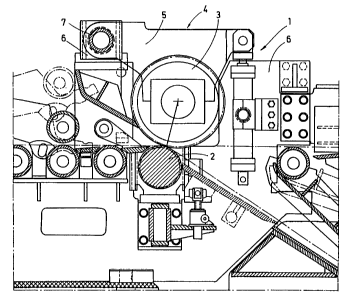
Fig. 1 of the drawing shows a driver 1 including a roll 2
which is mounted so as to be essentially stationary and a roll 3
which is adjustable relative to roll 2. The roll 3 is_.mounted in
a swivel frame 4 which is composed of two oppositely located links
5, 5' which have a common swivelling axis 7 in the frame 6 of the
driver 1. Pressure medium cylinders 8 are arranged at the ends of
the links 5, 5' located opposite the swivelling axis 7. The
pressure medium cylinders 8 are mounted in the frame 6 so as to be
capable of swivelling.
Fig. 2 of the drawing shows that the links 5, 5' are mounted
in the frame 6 so as to be capable of swivelling about the
swivelling axis 7. In the area of the swivelling axis 7, the links
5, 5' have a common base 9 which connects the links 5, 5' to one
another. The base 9 is composed of a torsion tube 10. The base 9
may also be composed of a plurality of concentrically arranged
torsion tubes. On the other hand, the base may be composed of one
or more torsion rods. The roll 3 is rotatably mounted in the links
5, 5'. Pressure medium cylinders 8, 8' act on the free ends of the
links 5, 5'.
7
21 T7342
The torsion tube 10 makes- it possible that, when different -
forces are applied, the links 5, 5' are also swivelled to a
different extent by the pressure medium cylinders 8, 8'. However,
the torsion tube 10 also ensures that the difference~in the swivel
range of the links 5, 5' does not exceed a predetermined dimension
which depends essentially on the stiffness of the torsion tube. By
introducing different adjusting forces with a relatively small
differential force of the pressure medium cylinders 8, 8', it is
possible to achieve different swivelling angles of the links 5, 5'
and, thus, of the roll 3. This makes it easily possible to
influence the tensile force exerted by the driver onto the strip by
a simple swivelling of the roll 3, so that an optimum distribution
of tensile forces can be achieved without difficulty.
While specific embodiments of the invention have been shown
and described in detail to illustrate the inventive principles, it
will be understood that the invention may be embodied otherwise
without departing from such principles.
8