Note: Descriptions are shown in the official language in which they were submitted.
CA 02178287 2001-03-07
RARE EARTH ELEMENT-DOPED MULTIPLE-CORE OPTICAL FIBER
AND METHOD FOR FABRICATING THE SAME
This invention relates to a rare earth element-doped optical fiber and, more
particularly, to a rare earth element-doped multiple-core optical fiber having
a high gain and
widely flat characteristics of gain to wavelength, and a method for
fabricating the same.
These days, an optical fiber amplifier using a rare earth element-doped
optical
fiber, which is doped with a rare earth element such as Er, Pr, Nd, etc. into
a core thereof,
has been developed and improved for practice. Especially, an Er-doped optical
fiber
l0 amplifier, which can provide a high gain and a high saturated output power
at the 1.55Nm
wavelength band, is expected to be applied to various optical systems. Its
application to
a high-speed, large-quantity, and long-distance optical transmission system
using a
wavelength division multiplexing transmission technique of more than several
channels
between 1.53Nm and 1.56Nm wavelength bands, and an optical CATV system, for
example, has been noted. In such optical transmission systems, it is important
that the Er-
doped optical fiber amplifier has flat gain characteristic in such wavelength
bands.
In order to realize such flat characteristics of gain to wavelength, an Er-
doped
multiple-core optical fiber and a method for fabricating the same have
previously been
proposed by the inventors. The optical fiber comprises a plurality of cores
doped with rare
2 0 earth elements, such as Er and AI together, and an outer cladding layer
which is provided
around the cores, each of which is directly covered by a primary cladding
layer. For this
structure, the cores can contain a much higher concentration of AI dopant than
a single
core of a conventional Er-doped optical fiber. Furthermore, gain of each core
is to be
lowered to obtain flat characteristics of gain to wavelength, then, high gain
is provided by
superposing all outputs thereof in addition to the flattened characteristics
of gain to
wavelength.
In an optical fiber amplifier using such a proposed Er-doped multiple-core
optical fiber, however, the inventors have found disadvantages in that when
the spacing
among the cores of the optical fiber become larger, gain suddenly drops,
although flat
characteristics of gain to wavelength in a wavelength band of 1.53Nm ~ 1.57um
are
obtained.
Accordingly, it is an object of the invention to provide a rare earth element-
doped multiple-core optical fiber, and a method for fabricating the same, by
which gain is
high and widely flat characteristics of gain to wavelength are obtained.
- 1 -
CA 02178287 2001-03-07
It is another object of the invention to provide a rare earth element-doped
multiple-core optical fiber, and a method for fabricating the same, by which a
lesser gain
drop occurs even if the spacing among the cores becomes large.
It is another object of the invention to provide a rare earth element-doped
multiple-core optical fiber, and a method for fabricating the same, by which
the excitation
light power becomes lower and the length of the optical fiber becomes shorter.
It is another object of the invention to provide a method for fabricating a
rare
earth element-doped multiple-core optical fiber, by which a rare earth element-
doped
multiple-core optical fiber having high gain and wide wavelength band
characteristics is
fabricated precisely and economically.
According to the first aspect of the invention, a rare earth element-doped
multiple-core optical fiber comprises: a plurality of cores each having a
refractive index of
nW doped with at least one rare earth element and AI therein; a plurality of
primary cladding
layers each having a refractive index of nP (nP < nW) doped with at least one
rare earth
element, and covering each of the cores; and an outer cladding layer having a
refractive
index of n~ (nW > n~ and nP s n~), and covering said plurality of cores
covered with the
plurality of primary cladding layers; wherein the cores are positioned
substantially on a
central axis of the outer cladding layer, and separated with a predetermined
spacing by the
plurality of primary cladding layers.
According to the second aspect of the invention, a rare earth element-doped
multiple-core optical fiber comprises: a plurality of cores each having a
refractive index of
nW doped with at least one rare earth element and AI therein; a plurality of
intermediate
cladding layers each having a refractive index of n; (n; < nW) doped with at
least one rare
earth element, and covering the plurality of cores; a plurality of primary
cladding layers
2 5 each having a refractive index of nP (nP s n; and np < nW) doped with at
least one rare earth
element, and covering the plurality of intermediate cladding layers; and an
outer cladding
layer having a refractive index of n~ (nw > n~, n; s n~ and nP s n~), and
covering the plurality
of cores covered with the plurality of intermediate and primary cladding
layers; wherein the
plurality of cores are positioned substantially on a central axis of the outer
cladding layer,
3 0 and separated with a predetermined spacing by the plurality of
intermediate cladding
layers.
According to the third aspect of the invention, a method for fabricating a
rare
earth element-doped multiple-core optical fiber comprises the steps of:
fabricating a
plurality of soot glass rods, each of which is provided with a core containing
AI and a
- 2 -
CA 02178287 2001-03-07
primary cladding layer directly covering the core; immersing the plurality of
soot glass rods
in a rare earth element-compound solution; picking up the plurality of soot
glass rods from
the solution, and drying and consolidating them to provide a plurality of rare
earth element
and AI co-doped transparent glass rods; inserting the plurality of co-doped
transparent
glass rods into a quartz tube; heating and collapsing the quartz tube thus
inserted with the
plurality of co-doped transparent glass rods to fabricate an optical fiber
preform rod; and
heating and drawing the optical fiber preform to provide a rare earth element-
doped
multiple-core optical fiber.
According to the fourth aspect of the invention, a method for fabricating a
rare
earth element-doped multiple-core optical fiber comprises the steps of:
fabricating a
plurality of soot glass rods, each of which is provided with a core containing
AI and an
intermediate cladding layer directly covering the core; immersing the
plurality of soot glass
rods in a rare earth element-compound solution; picking up the plurality of
soot glass rods
from the solution, drying and consolidating them to provide a plurality of
rare earth element
and AI co-doped transparent glass rods; covering each of the co-doped
transparent glass
rods with a primary cladding layer; inserting the plurality of co-doped
transparent glass rods
with the intermediate cladding layers and the primary cladding layers into a
quartz tube;
heating and collapsing the quartz tube to fabricate an optical fiber preform
rod; and heating
and drawing the optical fiber preform rod to provide a rare earth element-
doped multiple-
2 0 core optical fiber.
The invention will be explained in more detail in conjunction with the
appended
drawings, wherein:
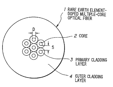
Figure 1 is a cross-sectional view showing a rare earth element-doped multiple-
core optical fiber according to the first preferred embodiment of the
invention,
2 5 Figure 2 is a cross-sectional view showing a rare earth element-doped
multiple
core optical fiber according to the second preferred embodiment of the
invention,
Figure 3 is a flow chart showing a method for fabricating a rare earth element-
doped multiple-core optical fiber which was formerly proposed by the
inventors,
Figure 4 is a graph showing the characteristics of gain to core spacing for
rare
3 0 earth element-doped multiple-core optical fibers according to the
invention and a rare earth
element-doped multiple-core optical fiber which was formerly proposed by the
inventors,
Figure 5 is a structural view showing a rare earth element-doped multiple-core
optical fiber amplifier,
- 3 -
CA 02178287 2001-03-07
Figure 6 represents (a) sectional views of two types of cores, each covered by
a primary cladding layer, of a rare earth element-doped multiple-core optical
fiber according
to the first preferred embodiment of the invention, (b) profiles of the
respective refractive
indices, and (c) profiles of the respective Er concentrations,
Figure 7 represents (a) sectional views of two types of cores, each covered by
an intermediate cladding layer and a primary cladding layer, of a rare earth
element-doped
multiple-core optical fiber according to the second preferred embodiment of
the invention,
(b) profiles of the respective refractive indices, and (c) profiles of the
respective Er
concentrations,
Figure 8 is a flow chart showing a method for fabricating a rare earth element-
doped multiple-core optical fiber according to the first preferred embodiment
of the
invention,
Figure 9 is a flow chart showing a method for fabricating a rare earth element-
doped multiple-core optical fiber according to the second preferred embodiment
of the
invention, and
Figure 10 is a flow chart showing a method for fabricating a rare earth
element-
doped multiple-core optical fiber according to the second preferred embodiment
of the
invention.
Before explaining a rare earth element-doped multiple-core optical fiber in
the
first preferred embodiment, the aforementioned rare earth element-doped
multiple-core
optical fiber, formerly proposed by the inventors, and a method for
fabricating the same will
be explained with reference to Figure 1.
The Er-doped optical fiber 1 comprises a plurality of cores 2 (seven cores in
this case) doped with Er and AI together, and an outer cladding layer 4 which
is provided
around the cores 2, each of which is directly covered by a primary cladding
layer 3.
Figure 5 shows a rare-earth element-doped multiple-core optical fiber
amplifier
using such an optical fiber, which comprises a certain length of a rare-earth
element-doped
multiple-core optical fiber 1, light sources (not shown) for emitting
excitation lights 11-1 and
11-2, to be injected through WDM couplers 8-1 and 8-2 into the optical fiber 1
at front and
3 0 rear stages, respectively.
In operation, the excitation lights 11-1 and 11-2 are coupled with single mode
optical fibers 9-1 and 9-2 through WDM couplers 8-1 and 8-2, then absorbed in
the optical
fiber 1 inherently to amplify a signal light 10-1 transmitted through the
optical fiber 1 to
- 4 -
CA 02178287 2001-03-07
obtain an amplified signal light 10-2. Optical isolators 7-1 and 7-2 are
preferably used for
suppressing a retrograde signal light of the amplified signal light 10-2.
Next, now referring to Figure 3, a method for fabricating an Er-doped multiple-
core optical fiber proposed by the inventors will be explained below.
Si02 -Ge02 -AI203 composite soot glass rods are fabricated by an ordinary
fabrication process such as VAD method (at step A). Next, the soot glass rods
are
immersed in an Er-compound solution (at step B). Then the soot glass rods are
picked up
from the solution, dried and consolidated by an electrical heater to obtain Er-
AI co-doped
Si02 -Ge02 transparent glass rods (at step C). After that, each of the rods is
covered by
a primary cladding layer by an ordinary fabrication process such as outer CVD
method (at
step D), the plurality of rods with the primary cladding layers are inserted
into a quartz tube
(at step E), and the quartz tube is heated by oxyhydrogen-burner and collapsed
to fabricate
an optical fiber preform rod (at step F). Finally, the optical fiber preform
is moved into an
electric heater at a predetermined speed to be heated, an end of the fused rod
is drawn
out of the heater and wound around a drum to provide an Er-doped multiple-core
optical
fiber (at step G).
According to such structure of the Er-doped multiple-core optical fiber, high
gain is obtained as well as the flat characteristics of gain to wavelength.
The reasons for
this will be explained in more detail by the following.
2 0 First, the cores can contain a much higher concentration of AI dopant than
a
single core in a conventional Er-doped optical fiber. Second, for this
structure, though a
gain of each core is to be lowered to obtain flat characteristics of gain to
wavelength, then
a high gain is provided by superposing all outputs thereof in addition to the
flattened
characteristics of gain to wavelength. The conventional characteristics of
gain to
2 5 wavelength show that injected excitation light power is lowered, the peak
of gain observed
near 1.535Nm wavelength decreases, and gain relative to wavelength becomes
flat
gradually. As the excitation light power becomes lower, a right hand
increasing~tendency
is observed, that is to say, the gain at a shorterwavelength band (1.53Nm
wavelength side)
becomes lower, and the gain at a longer wavelength band (1.56Nm wavelength
side)
3 0 becomes high. If the excitation light power is drastically reduced, the
gain is too low to be
used as an optical fiber amplifier. The Er-doped multiple-core optical fiber
proposed by the
inventors utilizes such principle actively. If an outer diameter D of the core
2, and a
spacing S among the cores 2 is optimized so that an excitation light and a
signal light are
almost equally distributed and transmitted in each core, a gain of each core
is low but a flat
- 5 -
CA 02178287 2001-03-07
gain relative to wavelength is obtained. The signal lights, being transmitted
through a
certain length of the fiber, are amplified in each core, respectively, and
superposed as an
output signal. As a result, the gain is high, and the characteristics of gain
to wavelength
are flattened.
In such Er-doped multiple-core optical fibers, however, there is disadvantage
as described below. The characteristics of gain to core spacing for optical
fiber amplifiers
using a variety of Er-doped multiple-core optical fibers have been measured.
The result
for an optical fiber amplifier which uses the optical fiber formerly proposed
by the inventors
having a core of approximately 2Nm diameter is indicated as "PRIOR EXAMPLE" in
Figure
4. The result shows that as the core spacing S(Nm) is increased, the gain G
(dB)
decreases drastically, as described before, although the flat characteristics
of gain to
wavelength become wider in 1.53Nm ~ 1.57Nm wavelength bands.
The reason for this is that optical isolators 7-1 and 7-2, and WDM couplers 8-
1
and 8-2 are made from the same fiber as the single mode optical fibers 9-1 and
9-2, each
of which is provided with, for example, a core of 10Nm diameter, a cladding
layer of 125Nm
diameter, and a specific refractive index difference of 0.3%. If the single
mode optical
fibers 9-1 and 9-2 are connected to both ends of the rare earth element-doped
multiple-
core optical fiber, a part of the signal lights and the excitation lights are
transmitted through
the primary cladding layer 3, in addition to being transmitted through the
seven cores 2 co-
t 0 doped with a rare earth element Er and AI. As a result, the power of such
partial lights
transmitted through each primary cladding layer 3 increases, as the core
spacing S
becomes larger. The inventors have studied this phenomenon and have found that
no rare
earth element is doped in each primary cladding layer to contribute to
amplifying the signal
light, so that the gain decreases as the core spacing S becomes larger.
2 5 Next, a rare earth element-doped optical fiber in the first preferred
embodiment
according to the invention will be explained with reference to Figure 1.
In the first preferred embodiment, a rare earth element-doped multiple-core
optical fiber 1 is provided with an outer cladding layer 4 having an
approximately circular
cross-section, and seven cores 2, each having a predetermined diameter D,
being
30 positioned substantially along the central axis of the cladding layer so as
to be separated
with a predetermined spacing S from each other by a primary cladding layer 3.
The outer
cladding layer 4 is made of Si02, or Si02 added with a dopant, such as F, Ge,
etc., for
controlling the refractive index and is generally formed to have an outer
diameter of
approximately 125pm. The primary cladding layer 3, which directly covers the
core 2, is
- 6 -
CA 02178287 2001-03-07
made of SiOz doped with Er, or Si02 doped with Er and F together, and formed
to have a
predetermined thickness so as to separate the cores 2 from each otherwith a
core spacing
S of 1.ONm ~ 1.5Nm. The refractive index nP of the primary cladding layer 3 is
to be lower
than the refractive index nW of the core 2, and is equal to or lower than the
refractive index
n~ of the outer cladding layer 4. It is preferable that the primary cladding
layer 3 contains
at least 50 ppm of Er, and a profile of Er concentration, which will be
explained later, may
be varied along the primary cladding layer thickness direction, or may be
constant.
Regarding the concentration of Er dopant in the primary cladding layer, the
higher it is, the
more the Er dopant contributes to the amplification of the signal light.
However, the upper
limit of Er dopant concentration should not exceed the Er concentration in the
core 2.
Figure 2 shows a rare earth element-doped optical fiber in the second
preferred
embodiment according to the invention, wherein like parts are indicated by
like reference
numerals as used in Figure 1. A rare earth element-doped optical fiber in the
second
preferred embodiment is provided with cores 2 each doped with Er and AI
together, being
directly covered by an intermediate cladding layer 5, and a primary cladding
layer 6
containing no rare earth element dopant to cover the intermediate cladding
layer 5 directly.
The refractive index nP of the primary cladding layer 6 is to be lower than a
refractive index
nw of the core 2, but equal to or lower than a refractive index n~ of the
outer cladding layer
4, and equal to or higher than the refractive index n, of the intermediate
cladding layer 5.
2 0 The material used as the primary cladding layer 6 is different from that
in the first preferred
embodiment, which may include Si02 without Er dopant, or Si02 doped with F, B,
or Ge.
The thickness thereof is predetermined to be much thinner than that of the
intermediate
cladding layer 5. The intermediate cladding layer 5 is made of Si02 doped with
at least 50
ppm of Er, which may additionally contain F, so as to amplify a signal light
transmitted
through the layer. In the second preferred embodiment, a spacing S among the
cores 2
is adjusted by controlling the thickness of the intermediate cladding layer 6.
Regarding the
concentration of Er dopant therein, the higher it is, the more the Er dopant
contributes to
amplifying the signal light, but the upper concentration limit of Er dopant is
determined not
to exceed the Er concentration in the core 2.
In the first and second preferred embodiments, the core diameter D is
determined as 1 s D < 3Nm so that the combined multiple core diameter is
substantially
equal to a mode-field diameter of the single mode optical fibers to be
connected thereto,
which is approximately 10Nm. The specific refractive index difference between
the cores
and the outer cladding layer, or between the cores and the primary cladding
layers is at
CA 02178287 2001-03-07
least 1 %. A higher specific refractive index difference is preferable for a
high gain
amplification, and a maximum value may be approximately 2.5%, which is
obtained by
adding F into the outer cladding layer or the primary cladding layer. The
material used as
the cores may include Er-AI co-doped Si02, Er-AI co-doped Si02 -Ge02 -P2 05,
Er-AI co-
doped Si02 -P2 O5, etc. and the concentration of Er dopant therein is at least
200 ppm and
may increase to approximately 1500 ppm. A higher concentration of Er is
preferable for
obtaining a high gain amplification and flat characteristics of gain to
wavelength. It is also
preferable that the concentration of AI dopant in the cores is at least 7000
ppm and may
increase to approximately 3.5% for obtaining flat characteristics of gain to
wavelength.
Besides Er, at least one other rare earth element such as Pr, Nd, Yb, Sm, Tm,
Ce, etc.
may be doped with AI into the cores.
Figure 6 shows two types, (A) and (B), of cores covered by primary cladding
layers in a rare earth element-doped multiple-core optical fiber according to
the first
preferred embodiment of the invention, wherein the enlarged cross-sectional
views,
refractive index profiles, and Er concentration profiles for types (A) and (B)
are indicated
by (a), (b), and (c), respectively. In type (A), the core 2 has a constant
refractive index
higher than that of a primary cladding layer 3. The Er concentration therein
has a quasi-
step profile. In type (B), the core 2 has a graded refractive index and the Er
concentration
therein has a nearly Gaussian distribution profile. Regarding the specific
refractive index
2 0 differences between cores 2 and primary cladding layers 3, approximately
the same values
may be obtained in type (A) and (B) by increasing the maximum value of
refractive index
in the core of type (B).
Figure 7 shows two types, (A) and (B), of cores covered by primary cladding
layers of a rare earth element-doped multiple-core optical fiber according to
the second
preferred embodiment of the invention. In type (A), core 2 has a constant
refractive index
higher than those of the intermediate cladding layer 5 and the primary
cladding layer 6,
then, it has a step index profile. The Er concentration therein has a quasi-
step profile. In
type (B), core 2 has a constant refractive index, and the intermediate
cladding layer 5 has
a refractive index lower than that of the core 2 and the primary cladding
layer 6 to provide
an approximately W-shaped refractive index profile. The Er concentration
therein has a
nearly Gaussian distribution profile.
In the invention, refractive indices and Er concentration profiles are
adjusted
by controlling conditions such as time for immersing a soot glass rod in an Er-
compound
_ g _
CA 02178287 2001-03-07
solution, Er concentration of the solution, time for drying the soot glass rod
after the
immersion, time and temperature for consolidation, etc.
Next, a method forfabricating a rare earth element-doped multiple-core optical
fiber according to the first preferred embodiment of the invention will be
explained with
reference to Figure 8. Soot glass rods comprising Si02 -Ge02 -AI2 03 for
cores, and Si02
or Si02 doped with F for primary cladding layers are fabricated by an All-
synthetic process
such as VAD method (at step A). Next, the soot glass rods are immersed in an
Er-
compound solution (at step B). In this process, the immersion time is
controlled so as to
provide certain Er concentration profiles thereof, such as a step or a
Gaussian distribution
as shown in Figure 6. Then the soot glass rods are picked up from the
solution, dried and
consolidated by an electrical heater to obtain Er-AI co-doped Si02 -Ge02
transparent glass
rods with primary cladding layers (at step C). After that, a plurality of rods
with primary
cladding layers are inserted into a quartz tube (at step D). The quartz tube
is evacuated,
heated by oxyhydrogen-burner from one end to another, and collapsed to
fabricate an
optical fiber preform rod (at step E). Finally, the optical fiber preform rod
is moved into an
electric heater at a predetermined speed to be heated, an end of the fused rod
is drawn
out of the heater and wound around a drum to provide an Er-doped multiple-core
optical
fiber (at step F)
Instead of step A, soot glass rods may be fabricated by two separate steps,
2 0 that is to say, fabricating soot glass rods for AI-containing cores, such
as Si02 -Ge02 -AI2
03 cores (at step A'), then producing primary cladding layers of soot glass
thin layers
around the soot glass rods (at step A"), as encircled by a broken line in
Figure 8. Both
steps may be processed by VAD method, and soot glass rods are fabricated by
using two
flame-hydrolysis-burners, which are positioned with a predetermined distance
on the
2 5 picking-up direction of the rods to provide an upper burner and a lower
burner. Soot glass
rods for cores and soot glass thin layers for primary cladding layers are
produced by the
upper and lower burners, respectively.
Next, a method for fabricating a rare earth element-doped multiple-core
optical
fiber according to the second preferred embodiment of the invention will be
explained in
3 0 Figure 9. Soot glass rods comprising Si02 -Ge02 -AIz 03 for cores and Si02
for
intermediate cladding layers are fabricated by an All-synthetic process such
as VAD
method (at step A). Next, the soot glass rods are immersed in an Er-compound
solution
(at step B). Then the soot glass rods are picked up, dried and consolidated by
an electrical
heater to obtain Er-AI co-doped Si02 -GeOz transparent glass rods with
intermediate
_ g _
CA 02178287 2001-03-07
v
cladding layers (at step C). After that, each of the rods is covered by a
primary cladding
layer in an ordinary fabrication process such as outer CVD method (at step D).
After that,
in the same manner as in the method for fabricating the optical fiber in the
first preferred
embodiment, the plurality of rods are inserted into a quartz tube (at step E).
The tube is
heated and collapsed to fabricate an optical fiber preform rod (at step F),
then, the optical
fiber preform rod is heated and drawn to provide an Er-doped multiple-core
optical fiber (at
step G). Besides step A, in the same manner as in the method for fabricating
the optical
fiber in the first preferred embodiment, soot glass rods may be fabricated by
two separate
steps, as shown encircled by a broken line in Figure 9. In this case, soot
glass rods for AI-
containing cores are fabricated (at step A'), and intermediate cladding layers
of soot glass
thin layers are produced around the soot glass rods (at step A"). Both steps
may be
processed by VAD method.
Another method for fabricating a rare earth element-doped multiple-core
optical
fiber according to the second preferred embodiment of the invention will be
explained in
Figure 10. Especially in this case, intermediate cladding layers are made of F-
doped Si02
(at step A). A step-shaped refractive index profile, which is shown in Figure
7(A), may be
obtained by using a material such as F-doped SiOZ for both primary cladding
layers and
the outer cladding layer, and a W-shaped refractive index profile, which is
shown in Figure
7(B), may be obtained by using Si02 or Ge-doped Si02.
2 0 A variety of Er-doped multiple-core optical fibers are fabricated in the
invention
by the methods described before, and the characteristics of gain to core
spacing are
measured for optical fiber amplifiers. TABLE 1 shows structural parameters of
such Er-AI
co-doped multiple-core optical fibers according to the invention, together
with an Er-AI co
doped multiple-core optical fiber which was formerly proposed by the inventors
for
comparison.
- 10 -
CA 02178287 2001-03-07
TABLE 1
PRIOR EXAbfPLE EXAMPLE EXAr(PLE EXAMPLE
1 2 3 4
EXAMPLE (FIG.6(A))(FIG.6(B))(FIG.7(A))(FIG.7(B))
Er-CONCENTRATION 400 400 400 400 400
(ppm)
A1-CONCENTRATION 8500 8500 8500 8500 8500
(ppm)
CORE REFRACTIVE1.4795 1.4795 1.4807 1.4795 1.4795
INDEX
OUTER 1.95 1.95 um 1.95 arm 1.95 um 1.95 um
arm
1 DIAbiETER
O
INTER- REFR.~1CTIVE- - - 1.458 1.447
MEDIATE INDEX (F-doped)
CLADDING
LAYER THICKNESS - - - 0.35 arm 0.35 pm
PRIMARY REFRACTIVE1.458 1.458 1.458 1.458 1.462
CLADDING INDEX (Ge-doped)
LAYER THICKNESS 0.5 ~Cm 0.5 Nm 0.5 um 0.15 ~m 0.15 um
OUTER REFRACTIVE1.458 1.458 1.458 1.458 1.462
CLADDING INDEX . (Ge-doped)
LAYER OUTER 125 um 125 )rm 125 um 125 arm 125 Nm
DIAMETER
The results are shown in Figure 4, wherein a solid line is obtained for
"EXAMPLE 1" in TABLE 1, a one-dotted line forthe "EXAMPLE 2", a two-dotted
line forthe
"EXAMPLE 3", and broken lines for the "EXAMPLE 4" and the "PRIOR EXAMPLE" are
obtained, respectively. As the core spacing S is increased, a gain is
drastically dropped
for the "PRIOR EXAMPLE". On the contrary, gains are high and slight decreases
are
observed in the respective examples of the invention. For example, in the Er-
AI co-doped
multiple-core optical fiber amplifier using the "EXAMPLE 1" fiber, a gain of
35 dB and a
wavelength band width where gain drops by 1 dB from its maximum value ("1 dB
band
width") of 26 nm at an input signal light power of -17 dBm are obtained. In
addition to that,
3 0 a gain of 29 dB and a 1 dB band width of 51 nm at an input signal light
power of -10 dBm
are obtained. This band width is 1.5 to 2.2 times as wide as that obtained by
the
conventional Er-doped optical fiber amplifiers.
- 11 -
CA 02178287 2001-03-07
i
In the invention, a rare earth element-doped multiple-core optical fiber is
not
limited to an optical fiber having seven cores as shown in Figures 1 and 2,
but may include
optical fibers having a different number of cores such as three, nine, and
nineteen cores.
As well explained above, the invention provides advantages set out below.
(1) A reduction in gain drop occurs even if the spacing among the cores
becomes larger. Therefore, in an optical fiber amplifier, gain is kept high
and widely flat
characteristics of gain to wavelength are obtained.
(2) The excitation light power is used effectively. Therefore, the power can
be
lower and a length of the optical fiber can be shorter.
(3) A rare earth element-doped multiple-core optical fiber having high gain
and
wide wavelength band characteristics is fabricated precisely and economically.
Although the invention has been described with respect to specific
embodiments for complete and clear disclosure, the appended claims are not to
be thus
limited but are to be construed as embodying all modifications and alternative
constructions
that may occur to one skilled in the art which fairly fall within the basic
teachings herein set
forth.
- 12 -