Note: Descriptions are shown in the official language in which they were submitted.
2 ~ t 8362
LIGHT SMITING RIGID, FRACTURAHLE PROJECTILE-TYPE
MARRING AMMUNITION AND ELECTRONIC STROBE FLASH APPARATUS
FOR AIR PO~IERED GUNS
BACKGROUND OF THE INVENTION
1. FIELD OF THE INVENTION
The present invention relates generally to light
emitting rigid, fracturable projectile-type marking
ammunition and electronic strobe flash apparatus for air
powered guns, and more specifically, to phosphorus
paintballs and an exciter adaptable for use with paintball
guns for exciting the phosphorus paintballs to emit light
and thus, provide a luminous trail when discharged from
the paintball gun.
2. DESCRIPTION OF THE PRIOR ART
Exercises or recreational activities involving
paintball guns have become quite popular. Participants
arranged in teams shoot paintballs at target participants
of opposing teams. When a paintball strikes a target
participant, it fractures and splatters a filler material,
marking the target participant. The marked participant is
disqualified from further participation in the exercise or
activity.
21 78362
2
Paintball guns known in the prior art are effective only
when used in adequate lighting. In adequate lighting, a user
can easily observe the impact of a paintball, and possibly the
trace of its path, and adjust his aim accordingly. This does
not hold true, however, when used in the dark because the user
cannot trace the path of the paintball and hence, cannot
determine with any amount of accuracy whether a targeted
participant has been hit.
A paintball gun capable of discharging luminous paintballs
overcomes the foregoing disadvantage of known paintball guns.
Paintball pellets capable of emitting light would provide a
luminous trail.
None of the paintball guns known in the prior art, taken
either singly or in combination, are seen to describe the
instant invention as claimed.
SUt~IARY OF THE INVENTION
The present invention is generally a paintball gun that
discharges luminous paintballs. More particularly, the instant
invention is to a paintball for use with an exciter for
exciting the paintball to emit light and thus, provide a
luminous trail when discharged from a paintball gun.
In accordance with an embodiment of the present invention
there is provided an exciter energized by a power source and
for use with a paintball gun for exciting paintballs to emit
light, the exciter comprising: a tube; a coupling for coupling
the tube to the muzzle of a paintball gun so as to
substantially coalign with the muzzle of the paintball gun; and
a light source supported adjacent the tube, the light source
being arranged to emit light into the tube.
21 7362 a
3
In accordance with another embodiment of the present
invention there is provided an exciter energized by a low
voltage power source and for use with a paintball gun for
exciting photon absorbing paintballs discharged from the
paintball gun, the exciter comprising: a housing; a tube
passing through the housing, the tube having a substantially
transparent region; a coupling for coupling the tube to the
muzzle of a paintball gun and substantially in coalignment with
the muzzle of the paintball gun; and an exciter circuit,
comprising: a detector comprising a light source and a light
sensor, the light source being arranged to emit light through
the substantially transparent region of the tube, the light
sensor being arranged to alternatively detect light emitted
from the light source and detect an interruption in light
emitted from the light when a paintball passes between the
light source and the light sensor; a high voltage generator
connected to the low voltage power source and being configured
to convert voltage from the low voltage power source to high
voltage; a high voltage storage element connected to the high
voltage generator; a flash bulb connected to the high voltage
storage element, the flash bulb being supported adjacent the
substantially transparent region of the tube; and a trigger
connected to the high voltage storage element and the flash
bulb, the trigger further being connected to the detector and
being controlled by the detector to set off the flash bulb when
the light sensor detects an interruption in light from the
light sensor.
These and other features of the present invention will
become readily apparent upon further review of the following
specification and drawings.
,_.Y
'~!
2~ ~~3s2
4
BRIEF DESCRIPTION OF THE DRAWINGS
FIG. 1 is a partial perspective view and partial block
diagram respectively showing a paintball and an exciter
according to the instant invention, and a paintball gun used
in combination therewith;
FIG. 2 is a perspective view of a paintball according to
the instant invention;
FIG. 3 is a partial section view of one embodiment of a
paintball according to the instant invention;
30
A
5
FIG. 4 is a partial section view of another
embodiment of a paintball according to the instant
invention.
FIG. 5 is a partially exploded, partially cutaway
perspective view of an exciter according to the instant
invention.
FIG. 6 is a section view of an adapter for coupling
the exciter to the muzzle of a paintball gun.
FIG. 7 is a diagramatic representation of an exciter
electrical circuit.
FIG. 8 is a schematic representation of an exciter
electrical circuit.
FIG. 9 is a diagramatic of a paintball being
discharged through the exciter.
FIG. 10 is a diagramatic representation of a
paintball approaching the emitter-detector pair.
FIG. 11 is a diagramatic representation of a
paintball interrupting infrared beam emitted from the
infrared light emitting diode of the emitter-detector
pair.
FIG. 12 is a diagramatic representation of a
paintball absorbing light from the strobe flash tubes
subsequent to the photo transistor of the emitter-detector
pair detecting an interruption in light emitted from the
infrared diode light emitting diode.
FIG. 13 is a diagramatic representation of an
alternative exciter employing a flash ring leading the
emitter-detector pair.
2 ~ I~362
6
Similar reference characters denote corresponding
features consistently throughout the attached drawings.
DETAILED DESCRIPTION OF THE PREFERRED EMBODIMENTS
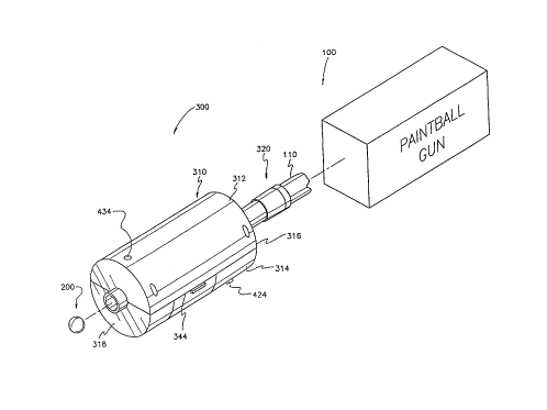
Now, with reference to the drawings, FIG. 1 shows a
paintball gun 100 adaptable for use in discharging light
emitting paintball projectiles 200, and more
particularly, a phosphorescent paintball 200 and an
exciter 300 for use in combination with a paintball gun
100. The exciter 300 excites the phosphorescent paintball
200 to emit light and provide a luminous trail when
discharged from a paintball gun 100. The travel of a
paintball 200 may be traced in a dark or poorly lit
environment.
An exciter 300 is shown coupled to the muzzle 110 of
a paintball gun 100. The exciter 300 comprises a
cylindrical housing 310 formed of diametrically disposed
halves 312, 314. The housing 310 has a proximal end 316
and a distal end 318. An adapter 320 extending from the
proximal end 316 of the housing 310 is configured to
couple the exciter 300 to the muzzle 110 of the paintball
gun 100.
Upon discharging a paintball 200 from the paintball
gun 100, the paintball 200 exits through the muzzle 110 of
the paintball gun 100, and then passes through the exciter
300 coupled to the muzzle 110. As the paintball 200
passes through the exciter 300, the paintball 200 is
excited to emit light. The light emitting paintball 200
w 2i 7832
7
exiting the exciter 300 provides a luminous trail which
permits the path of the paintball 200 to be traced.
A paintball 200, as shown in FIG. 2, comprises a
spherical capsule 210 defining an interior chamber 212,
and a filler (such the filler in FIGS. 3 and 4) contained
within the interior chamber 212. Typical capsules are
approximately 1.496 centimeters (cm) in diameter.
The capsule 210 is formed of two half spheres 216,
218. These hemispheres 216, 218 are fused together along
a sealing area defined by the adjoining hemisphere edges,
thus providing a fusion band 220. As the hemispheres 216,
218 are fused together, the filler is injected into the
capsule 210 as it is being sealed. The capsule 210 is
formed of a material impervious to the filler, and is of a
thickness suitable to support the filler and withstand
discharge, yet fracture upon impact. It is preferable
that the thickness of the capsule 210 according to the
instant invention ranges from 0.7 to 1.2 millimeters (mm).
It is preferable that the filler be washable.
Moreover, the filler is preferably not injurious to a
targeted participant (not shown). Furthermore, the filler
is preferably biodegradable and safe to the environment.
FIG. 3 shows a paintball 200A comprising a capsule
210A impregnated with phosphorescent material. The
capsule 210A preferably comprises 90-95 percent gelatin
with 5-10 percent Zinc Sulfide (ZnS) doped with some
photon absorbing or emitting material, such as Copper
(Cu++) (ZnS,Cu++). The gelatin is preferably
2;~~5~2
8
substantially transparent or translucent to permit maximum
exposure of the phosphorescent material to incident
radiation. Moreover, it is preferable that the thickness
of this capsule 210A ranges between 0.8 to 1.2 millimeters
(mm) to sufficiently excite the phosphorescent material.
The thickness of the capsule 210A is also critical to
provide sufficient structural integrity upon discharge yet
fracture easily upon impact to splatter the filler 214A
while causing minimum impact string to a targeted
participant (not shown). A transparent glycerin filler
214A is provided in this embodiment.
An alternative paintball 200B is shown in FIG.4.
This embodiment is provided with a substantially
transparent or translucent capsule 210B. Although the
capsule 210B may be formed of any material sufficiently
rigid to support a filler or solvent (and more
particularly a dispersing medium) 214B and withstand
discharge yet be frangible upon impact, a gelatin capsule
is preferred. In this embodiment, it is preferable that
the capsule 210B have a thickness ranging from 0.7 to 0.9
millimeter (mm). The filler 214B in this embodiment is
mixed with a surfactant (such as a commercial surface
active agent) or dispersing agent and a phosphorescent
material. Although the filler 214B preferably comprises a
member of an organic group consisting of compounds
referred to as triols, and in this case transparent
glycerin or glycol, an alkyltriol, any solvent or family
of solvents with properties of being insolvent with, and
... 21783b2
9
permitting the dispersing agent to disperse, the
phosphorous material will suffice. The phosphorescent
material is preferably comprised of 2-6 percent Zinc
Sulfide (ZnS) doped with Copper (Cu++) (ZnS,Cu++).
Surfactants for use with ZnS,Cu++ to obtain stable
suspension include Alkaterge T-IV, Zelec NK Antistat,
Amitex-E, Alkterge T, Tween 80, and Tween 20. To obtain
best result, a ratio of 6:4 of surfactant to ZnS,Cu++ by
weight should be used.
In use, exposure of either paintball 200A, 200B to
light excites the phosphorescent material to emit light.
The phosphorescent material is best excited by
ultraviolet rich light, and black light is twice as
effective as incandescent light.
Light emitting paintballs 200A, 200B provide a
luminous trail when discharged. The color of the trail
varies in accordance with the composition of the paintball
200A, 200B. Various basic materials may be doped with
various activators to emit different color lights. Basic
materials include but are not limited to Zinc, Zn, Sulfide
S, Calcium Ca, and Strotium Sr. Activators may include but
are not limited to Copper Cu, Manganese Mn, and Bismith
Bi. Zinc Sulfide ZnS doped with copper Cu (ZnS,Cu++), as
set forth above, emits a green trail. Zinc Sulfide ZnS
doped with Calcium Ca and Manganese Mn (ZnS(Cu,Mn)) emits
a yellow or orange trail. And Calcium and Strontium
Sulfide (Ca, Sr) S doped with Bismith Bi ( (Ca, Sr) S, Bi) emits
a blue trail.
2~7~3362
Referring back to FIG. 1, an exciter 300 for exciting
phosphorescent paintballs is shown comprising a
cylindrical housing 310 having diametrically disposed half
sections 312, 314, a proximal end 316, and a distal end
5 318.
An adapter 320 extends from the proximal and 316 of
the housing 310. The adapted 320 is configured to couple
the exciter 300 to the muzzle 110 of a paintball gun. As
shown in FIG. 6, the adapter 320 comprises a tubular
10 member 322 having a proximal end 324 and a distal end 326
respectively defining the proximal end and distal end of
the adapter 320. The distal end 326 of the tubular member
322 is adjoined concentrically to the proximal end 316 of
the housing 310, such as though some adhesion, fusion, or
molding process. The proximal end 324 of the tubular
member 322 is provided with tapered male threads 328, and
has a plurality of longitudinal slits 330 therein
extending substantially perpendicular to the tapered male
threads 328.
A collar 332 having female threads 334 is matingly
engagable with the beveled male threads 328 of the tubular
member 322. As the collar 332 threadably engages the
tubular member 322, the slits 330 are drawn closed. As
the slits 330 are drawn closed, the proximal end 324 of
the tubular member 322 frictionally engages the muzzle 110
of a paintball gun. Although plurality of slits 330
produce greater frictional contact, a single slit 330 may
suffice.
2178362
11
As is clearly shown in the drawing, a concentric
inner abutment surface 336 is provided within the tubular
member 322. This abutment surface 336 limits the travel
of the muzzle 110 within the tubular member 322 yet
enables the muzzle 110 to extend a predetermined distance
D1 beyond the slits 330 to provide a substantially
enclosed junction at the juncture adapter 320 and muzzle
110.
Referring back to FIG. 1, the exciter 300 further
includes a switch 424, such as the toggle switch shown.
The switch 422 enables and disables the exciter circuit
400 (shown in FIG. 7 and described hereinbelow). A neon
indicator 434 is located on top of the housing 310 and at
the distal end 318m of the housing 310. The neon indicator
434 is electrically connected to the switch 424 and
illuminates when the switch 424 is closed, providing the
user with an indication that the exciter circuit 400 is
enabled.
Referring also to FIG. 5, the exciter 300 also
comprises an arcuate shaped cover 338 which is structured
and configured to conform substantially flush with, and
define in part, the cylindrical housing 310. The cover
338 releasably engages the housing 310 and forms an access
cover for a battery compartment 340 which is provided to
contain a low voltage power source 404, such as the
plurality of 1.5 VDC batteries shown. The power source
404 energizes the exciter circuit 400 when the switch 424
is closed.
12
As shown in the drawings, the housing 310 includes
opposite sides 342, 344. Likewise, the cover 338 includes
opposite side edges 346, 348. These side edges 346, 348
correspond to the opposite sides 342, 344 of the housing
310. The side edges 346, 348 of the cover 338 abut the
sides 344, 342 of the housing 310 when the cover 338
engages the housing 310.
Openings 350 are formed along the sides 342 (however,
not shown in one side 344) of the housing 310. Hooks 352
extending upwardly from the side edges 346, 348 of the
cover 338 are structured and configured to engage
corresponding openings 350 along respective sides 344, 342
of the housing 310. The arcuate structure of the cover
338 normally biases the hooks 352 outward within the
corresponding openings 350 to engage the hooks 352 with
the structure of the housing 310 forming the openings 350,
thus latching the cover 338 to the housing 310. To
unlatch the cover 338 from the housing 310, simply depress
one or both sides of the cover 338 inward. This displaces
the hooks 352 inward out of contact with the structure of
the housing 310 forming the openings 350, and thus permits
the cove 338 to be separated from the housing 310.
A nodule 354 is provided along one side 346 of the
cover 338 proximate a hook 352 to assist the user in
identifying the location of the hook 352 when the cover
338 is attached to the housing 310. Moreover, indicia,
such as the term " Open ", may be inscribed on the cover
13
338 proximate the nodule 354 to assist the user in
identifying the function of the nodule 354.
Now, referring only to FIG. 5, the housing 310 of
the exciter 300 defines an interior chamber 356. The
interior chamber 356 contains the exciter circuit 400
(shown clearly in FIGS. 7 and 8) and has a tube 38
passing concentrically therethrough. The tube 358 has a
proximal end 360 (shown in FIG. 6) and a distal end 362,
and is at least partially transparent to permit light to
pass therethrough. The proximal end 360 of the tube 358
is preferably attached to the proximal end 316 of the
housing 310, and the distal end 362 of the tube 358 is
preferably attached to the distal end 318 of the housing
310, thus maintaining the tube 358 in a fixed position
within the chamber 356.
The tube 358 has a head 364 attached to its proximal
end 360 and a support member 366 attached to its distal
end 362. The head 364 comprises a six pin female
connector 368, and supports an infrared light emitting
diode 456 (shown in FIGS. 9 through 12), a photo
transistor 458 and a pair of diametrically disposed flash
tubes 402 (the second of which is clearly shown in FIGS.
9 through 12) in close proximity to the tube 358. The
support member 366 includes an upper extension 370 having
lateral groove 372 therein.
A circuit board 374 extending longitudinally within
the chamber 356 has a proximal end 376 and a distal end
378. A six pin male connector 380 is integral with the
_ ~~~ ~~3b~
14
proximal end 376 of the circuit board 374. This connector
380 is matingly engageable with the female connector 368
on the head 364 and thus, supports the proximal end 376 of
the circuit board 374. The distal end 378 of the circuit
board 374 is frictionally engageable with the lateral
groove 372 in the support member 366. This supports the
distal end 378 of the circuit board 374.
With reference to FIGS. 7 and 8, an exciter circuit
400 includes a pair of energizable flash tubes 402
arranged to project light in a direction interiorly of the
exciter tube 358 (as is shown in FIGS. 10 through 23), a
low voltage power source 404 for providing charging
energy, a high voltage storage element or capacitor 406
coupled to the flash tubes 402, a high voltage generator
circuit 408 for providing charging current from the power
source 404 to the high voltage capacitor 406 until the
capacitor 406 is charged to a predetermined voltage, a
trigger circuit 410 for generating a trigger voltage to
set off the flash tubes 402, and a detector circuit 412
for controlling the trigger circuit 410.
A high voltage generator circuit 408 similar to that
of the instant invention is set forth in U.S. Patent No.
3,822,393, issued July 2, 1974 to Zvi Y. Karpol. The high
voltage generator circuit 408 comprises a step up
transformer 414 having one terminal of its primary winding
416 coupled to the positive side of the low voltage power
source 404 through an RL network 420, and the other
terminal of its secondary winding 416 is coupled to the
217832
base of an oscillator transistor 422. The emitter of the
oscillator transistor 422 is connected to the negative
side of the power source 404 through a switch 424. The
collector of the oscillator transistor 422 is connected to
5 one terminal of the secondary winding 426 of the step up
transformer 414, and of which the other terminal is
coupled to the cathode of the flash tube 402 through a
rectifier diode 428. A high frequency coupling capacitor
430 has one terminal connected to the junction of the
10 terminal of the secondary winding 426 and the collector of
the oscillator transistor 422, and the other terminal
connected to a terminal of the high voltage capacitor 406.
The other terminal of the high voltage capacitor 406 is
connected to the junction of the emitter of the oscillator
15 transistor 422 and switch 424 through a bleeder resistor
432, a neon indicator 434 and current limiting resistor
436, and a filter capacitor 438. The high voltage
generator 408 converts the 1.5 VDC power source 404 to
approximately 250 VDC, which is stored in the high voltage
capacitor 406.
The trigger circuit 410 for discharging the high
voltage capacitor 406 is similar to that shown and
described in U.S. Patent No. 5,287,134, issued February
15, 1994 to J. David Cocca. The trigger circuit 410
includes the series combination of a resistor 440 and a
discharge trigger SCR 442 connected across the high
voltage capacitor 406. The junction between the resistor
440 and the anode of the discharge trigger SCR 442 is
16
connected to one terminal of a coupling capacitor 444, the
other terminal of which is connected to one end of the
primary winding 446 of a trigger transformer 448. The
other terminal of the primary winding 446 of the trigger
transformer 448 is connected to the cathode of the
discharge trigger SCR 442. The secondary winding 450 of
trigger transformer 448 is connected to the gate of the
flash tube 402. The anode terminal of the flash tube 402
is connected to the junction of the resistor 440 connected
to the anode of the discharge trigger SCR 442 and the high
voltage capacitor 406, and the cathode of flash tube 402
is connected to the cathode of the discharge trigger SCR
442 at the junction of the rectifier diode 428. The flash
tube 402 is triggered into conduction by a 3000 VDC signal
produced by the trigger transformer 448 at the gate of the
flash tube 402 and emits a flash of light during the
discharge of the high voltage capacitor 406 in response to
a flash trigger signal provided from the detector circuit
412.
The detector circuit 412 comprises an emitter-
detector pair 452, a switching amplifier 454, and a RC
network 456. The emitter-detector pair 452 is comprised
of a light emitting diode 458 and the photo transistor
460. The anode of the diode 458 is connected to the
positive side of the low voltage power source 404. A
current limiting resistor 462 couples the cathode of the
diode 458 to the negative side of the power source 404
through the switch 424. The open base of the photo
2~ 7~~3~2
17
transistor 460 is arranged to detect light emitted from
the diode 458. A resistor 464 is connected to the emitter
of the photo transistor 460. A coupling capacitor 466 has
one terminal connected to the junction of the emitter of
the photo transistor 460 and the emitter resistor 464, and
the other terminal is connected to the base of the
switching amplifier 454. A pull up resistor 468 is
connected at the junction of the coupling capacitor 466
and the base of the switching amplifier 454. A resister
470 is connected the collector of the switching amplifier
454, and a coupling capacitor 472 has one terminal
connected to the junction of the collector of the
switching amplifier 454 and the collector resistor 470,
the other terminal of which is connected to the gate of
the discharge SCR 442. A pull down resistor 474 is
connected at the junction of the coupling capacitor 472
and the gate of the discharge trigger SCR 442. The
coupling connector 472 and the pull down resistor 474 form
an RC network which provides a desired time delay for
reaching the gate voltage of the discharge trigger SCR
442. Since a paintball 100 (shown in Figs. 2, 2A and 2B
above) travels at a rate of 80 to 100 meters (m) per
second leaving the muzzle 110, a delay of 0.1 to 0.015
milliseconds (ms) is required before the trigger circuit
410 sets off the flash tubes 402. A Zener diode 476
connected to the collector of the photo transistor 460
regulates the voltage across the photo transistor 460,
switching amplifier 454, and the gate of the discharge
2~783b2
18
trigger SCR 442 to 9 VDC, and a resistor 478 connecting
the collector resistor 470 of the switching amplifier 454
and the node resistor 440 of the discharge trigger SCR
442 is a voltage control resistor for the low voltage
supply 404.
As shown in FIGS. 9 through 12, and further referring
to FIGS. 7 and 8, in operation, the exciter 300 is coupled
to the muzzle 110 of a paintball gun. The exciter 300 is
energized by closing the switch 424. Upon closing the
switch 424, the infrared light emitting diode 458 emits an
infrared beam across the tube 358 passing through the
exciter housing 310. The presence of the infrared beam is
detected by the photo transistor 460, as is shown in FIG.
10. As a phosphorescent paintball 200 is discharged from
the paintball gun 100, it enters the tube 358 passing
through the housing 310 of the exciter 300. As the
paintball 200 passes between the diode 458 and the photo
transistor 460, the infrared beam emitted from the
infrared diode 458 is interrupted, as is shown in FIG. 11.
The photo transistor 460 detects the interruption in the
infrared beam. The interruption in the infrared beam is
detected by the photo transistor 460, which produces a
pulse at its output. The output of the photo transistor
460 is amplified by the switching amplifier switch 454.
The output of the switching amplifier 454 triggers the
discharge trigger SCR 442. The RC network 456 provides a
desired time delay for triggering the discharge trigger
SCR 442 to compensate for the travel of the paintball 200
2~~8362
19
and the distance between the flash tubes 402 and the
emitter detector pair 452. When the discharge trigger SCR
442 is triggered, the high voltage capacitor 406
discharges through the trigger transformer, stepping up
the 250 VDC stored therein to produce a 3000 VDC signal at
the electrode of the flash tube 402, causing the flash
tube 402 to flash an ultra violet rich light, as shown in
FIG. 12. When the strobe lamp 402 flashes, the paintball
200 is excited, that is, the phosphorescent material in
the paintball 200 absorbs the light emitted from the flash
tube 402. Subsequent to this exposure, the paintball 200
continues to emit light, providing a luminous trail.
FIG. 13 shows an alternative arrangement wherein a
flash ring 402A is employed. The flash ring 402A leads
the diode 458 and the photo transistor 460. As the
leading edge of a paintball 200 being discharged
interrupts the signal from the light emitting diode 458,
the trigger circuit 410 ( shown in FIGS . 7 and 8 ) triggers
the flash ring 402A to emit and flash of ultraviolet rich
light which is absorbed by the phosphorous material in the
paintball 200. A flash ring 402A may irradiate the
paintball with more light, it may be more costly than a
conventional flash tube 402. It should be noted that the
arrangement of either the flash tube 402, a plurality of
flash tubes 402, or the flash ring 402A may lead or lag
the emitter-detector pair 452, and may be arranged
adjacent one another or may be spaced apart.
20
It is further to be understood that the present
invention is not limited to the sole embodiment described
above, but encompasses any and all embodiments within the
scope of the following claims.