Note: Descriptions are shown in the official language in which they were submitted.
- 2118881
SCROLL TYPE FLUID MACHINE
BACKGROUND OF THE INVENTION:
Field of the Invention:
The present invention relates to a scroll type
fluid machine to be used as a compressor or an expander.
Description of the Prior Art:
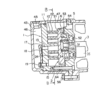
One example of a conventional scroll type
compressor is shown in Fig. 2 and Fig. 3. In Fig. 2,
numeral 4 designates a hermetic housing consisting of a cup-
like right hand housing 49, a frame 5 and a cup-like left
hand housing 43 and all these components are connected one
another by bolts 56. Within the right hand housing 49, an
electrical motor M is disposed, and within the left hand
housing 43, a scroll type compression mechanism C is
disposed, respectively.
The electrical motor M and the scroll type
compression mechanism C are connected each other via
a rotating shaft 3.
The right hand end of the rotating shaft 3 is
rotatably supported by the right hand housing 49 via a
sub-bearing 51 and the left hand end of same is rotatably
supported by the frame 5 via a main bearing 52.
The electrical motor M consists of a rotor Ma and
a stator Mb, and the rotor Ma is fixed to the rotating shaft
- 1 -
2118881
3 and the stator Mb is fixed to the right hand housing 49
by means of press fitting.
The scroll type compression mechanism C consists
of a stationary scroll 1, a swivel scroll 2, a rotation
prevention mechanism 6 of an Oldham link etc. to prevent
rotation of the,swivel scroll 2, etc.
The stationary scroll 1 comprises an end plate 11
and a spiral wrap 12 provided standingly on the inner
surface of said end plate, and by the outer circumferential
surface of the end plate 11 being sealingly contacted to
the inner circumferential surface of the left hand housing
43, a discharge chamber 46 is formed on the left hand side
of the end plate 11 and a suction chamber 47 is deffined on
the right hand side of same. At the center portion of the
end plate 11, a discharge port 13 is holed so that this
discharge port 13 is opened and closed by a discharge valve
_17 .
The swivel scroll 2 comprises an end plate 21 and
a spiral wrap 22 provided standingly on the inner surface of
said end plate, and within a boss 23 provided standingly on
the outer surface of the end plate 21, a drive bush 32 is
fitted in rotatably via s swivel bearing 34. Within a slide
groove 33 holed in the drive bush 32, an eccentric drive pin
31 provided projectingly from the left hand end of the
rotating shaft 3 is fitted in slidably.
- 2 -
2178881
The stationary scroll 1 and the swivel scroll 2
are engaged with each other with eccentricity of a
predetermined distance and with deviation of angle of 180
degree, thereby a plurality of closed cavities 24 are
formed.
Upon the electrical motor M being driven, the
swivel scroll 2 is driven via s swivel drive mechanism
consisting of the rotating shaft 3, the eccentric drive pin
31, the drive bush 32, the boss 23, etc., and the swivel
scroll 2, while being prevented from rotating by the
rotation prevention mechanism 6, makes revolutional swivel
motions on a circular track of a revolutional swivel radius.
Thereupon, gas enters a low pressure chamber 48
through a suction port 44, and said gas, while it passes
through a passage 58- provided around the outer circumference
of the stator Mb and through a gap 59 between the stator Mb
and the rotor Ma, cools the electrical motor M and then is
sucked into the closed cavities 24 through a passage 54
provided in the frame 5 and through the suction chamber 47.
Then, accompanying with the volumes of the closed
cavities 24 being reduced by the revolutional swivel motions
of the swivel scroll 2, the gas comes to the central portion
while it is compressed, passes the central portion and the
discharge port 13, opens forcibly the discharge valve 17 to
be discharged into the discharge chamber 46 and then flows
- 3 -
2178881
to the outside through a discharge port 45.
Incidentally, numeral 18 designates a valve
pressure to limit the opening of the discharge valve 17,
said valve pressure being fixed together with the discharge
valve 17 to the outer surface of the end plate 11 of the
stationary scroll 1. Numeral 62 designates a glass
terminal, and the electric power is supplied to the stator
Mb of the electrical motor M via said glass terminal 62.
Numeral 35 designates a balance weight fixed to the rotating
shaft 3.
In the conventional scroll type compressor as
mentioned above, as shown in Fig. 3, the end plate 21 of
the swivel scroll 2 is formed circular, and so as not to
touch said end plate 21, a plurality of legs 15 (four legs
in the figure) projecting to the right hand direction from
the outer circumferential edge of the end plate 11 of the
_ stationary scroll 1 are provided and said legs 15 are fixed
to the frame 5 by bolts 64, thus there is a problem that the
diameter of the end plate 11 of the stationary scroll 1
becomes larger and, accompanying therewith, the diameter of
the hermetic housing 4 becomes also larger.
SUMMARY OF THE INVENTION:
In order to dissolve the above-mentioned problem
in the prior art, the present invention is disclosed with
- 4 -
CA 02178881 2000-06-15
a feature that a cut out recess portion is provided at
each position, corresponding to said plurality of legs,
of the outer circumferential portion of the circular end
plate of the swivel scroll, wherein, when the swivel
scroll makes revolutional swivel motions, said plurality
of legs of the stationary scroll make relative movements
within each cut out recess portion so as not to
interfere with the end plate of the swivel scroll.
In an aspect of the present invention, there is
provided an arrangement in a scroll type fluid machine,
comprising: a sealed housing; a frame in said sealed
housing supporting a rotating shaft via a bearing; a
stationary scroll in said housing, said stationary scroll
comprising an end plate; a plurality of legs on an outer
circumferential edge of said end plate of said stationary
scroll fixed to said frame by bolts; a swivel scroll in
said housing engaged with said stationary scroll, said
swivel scroll having a circular end plate having an outer
circumferential portion and a swivel wrap, and said
swivel scroll being connected with said rotating shaft so
as to be able to make revolutional swivel motions upon
rotation of said shaft, said swivel scroll having a
swivel center; a rotation prevention mechanism interposed
between said frame and said swivel scroll; and a
plurality of cut out recess portions on said outer
circumferential portion of said circular end plate of
said swivel scroll located at positions corresponding to
and receiving respective ones of said plurality of legs,
each of said cut out recess portions having a shape
having a depth and width so as to avoid interference with
the respective one of said plurality of legs upon said
swivel scroll undergoing revolutional swivel motions.
- 5 -
CA 02178881 2000-06-15
In a further aspect of the present invention,
there is provided an arrangement in a scroll type fluid
machine, comprising: a sealed housing; a frame in said
sealed housing supporting a rotating shaft via a bea ring;
a stationary scroll in said housing, said stationary
scroll comprising an end plate; a plurality of legs on an
outer circumferential edge of said end plate of said
stationary scroll fixed to said frame by bolts; a swivel
scroll in said housing engaged with said stationary
scroll, said swivel scroll having a circular end plate
having an outer circumferential portion and a swivel
wrap, and said swivel scroll being connected with said
rotating shaft so as to be able to make revolutional
swivel motions upon rotation of said shaft, said swivel
scroll having a swivel center; a rotation prevention
mechanism interposed between said frame and said swivel
scroll; and a plurality of cut out recess portions on
said outer circumferential portion of said circular end
plate of said swivel scroll located at positions
corresponding to respective ones of said plurality of
legs, each of said cut out recess portions having a shape
having a depth and width sufficient to avoid interference
with the respective one of said plurality of legs upon
said swivel scroll undergoing revolutional swivel
motions, and the depth of each of said plurality of cut
out recess portions being such as to extend to an
imaginary circle defined by a radius formed by the line
between the swivel center of said swivel scroll and an
outermost end of said swivel wrap.
In yet a further aspect of the present
invention, there is provided a scroll type fluid machine,
comprising: a sealed housing comprising a pair of cup-
- 5a -
CA 02178881 2000-08-10
shaped housing portions, each of said cup-shaped housing
portions having an open end side having a clamping flange
thereat and each of said cup-shaped housing portions
being joined to the other of said cup-shaped housing
portions by said clamping flange; a frame having an outer
circumferential flange, said frame being fixed in said
sealed housing by having said outer circumferential
flange interposed between said clamping flanges of said
pair of cup-shaped housing portions; a rotating shaft
rotatably supported by said frame; an electric motor
contained within one of said cup-shaped housing portions
of said sealed housing and connected with one end of said
rotating shaft; a stationary scroll in the other one of
said cup-shaped housing portions of said sealed housing,
said stationary scroll comprising an end plate; a
plurality of legs extending axially from an outer
circumferential edge of said end plate of said stationary
scroll and fixed to said frame by bolts; a swivel scroll
engaged with said stationary scroll and supported in a
direction of thrust by said frame, said swivel scroll
having a circular end plate having an outer
circumferential portion and a swivel wrap, and said
swivel scroll being connected with the other end of said
rotating shaft so as to be able to make revolutional
swivel motions upon rotation of said shaft, said swivel
scroll having a swivel center; a rotation prevention
mechanism interposed between said frame and said swivel
scroll; and a plurality of cut out recess portions on
said outer circumferential portion of said circular end
plate of said swivel scroll located at positions
corresponding to respective ones of said plurality of
legs, each of said cut out recess portions having a shape
having a depth and width sufficient to avoid interference
- 5b -
CA 02178881 2000-08-10
with the respective one of said plurality of legs upon
said swivel scroll undergoing revolutional swivel
motions, and the depth of each of said plurality of cut
out recess portions being such as to extend to an
imaginary circle defined by a radius formed by the line
between the swivel center of said swivel scroll and an
outermost end of said swivel wrap.
BRIEF DESCRIPTION OF THE DRAWINGS:
In the accompanying drawings:
Fig. 1 shows a scroll type compressor of one
preferred embodiment according to the present invention,
wherein Fig. 1(A) is a partial longitudinal sectional
view taken along line A-A of Fig. 1(B) and Fig.,l(B) is a
transverse sectional view taken along line B-B of Fig.
1 (A) .
Fig. 2 is a longitudinal sectional view of a
scroll type compressor in the prior art.
Fig. 3 is a transverse sectional view taken
along line B-B of Fig. 2.
DESCRIPTION OF THE PREFERRED EMBODIMENTS:
One preferred embodiment according to the
present invention is shown in Fig. 1. As shown in Fig.
1(B), a cut out recess portion is formed at each
position, corresponding
- 5c -
2~ Tsaa~
to a plurality of legs 15 of the stationary scroll, of the
outer circumferential portion of the circular end plate 21
of the swivel scroll 2.
Said cut out recess portion 25 is of a shape
having such sufficient depth d and width w that the end
plate 11 of the swivel scroll 2 may not interfere with the
legs 15, when the swivel scroll 2 makes revolutional swivel
motions.
Other constructions are same as those of the
conventional one shown in Figs. 2 and 3, and corresponding
components and parts are given same numerals and description
is omitted.
Moreover, when the swivel scroll 2 makes
revolutional swivel motions, the legs 15 of the stationary
scroll 1 make relative movements within each cut out recess
portion 25 so as not to interfere with the end plate 21 of
the swivel scroll 2.
Accordingly, the fitting position of the legs 15
of the stationary scroll 1 can be moved to the centripetal
direction by a length corresponding to the depth d of the
cut out recess portion 25, as a result the diameter of the
end plate 11 of the stationary scroll 1 can be shortened by
the same length and the diameter of the hermetic housing 4
can be made smaller.
According to the present invention, as a cut out
- 6 -
2178881
recess portion is provided at each position, corresponding
to the plurality of legs of the stationary scroll, of the
outer circumferential portion of the circular end plate 21
of the swivel scroll, the legs of the stationary scroll does
not interfere with the end plate of the swivel scroll when
the swivel scroll makes revolutional swivel motions.
Thus, the fitting position of the legs of the
stationary scroll can be moved to the centripetal direction
by a length corresponding to the depth of the cut out recess
portion, as a result the diameter of the end plate of the
stationary scroll can be shortened by the same length and
the diameter of the hermetic housing can be made smaller.
While the preferred form of the present invention
has been described, variations thereto will occur to those
skilled in the art within the scope of the present inventive
concepts which are delineated by the following claims.