Note: Descriptions are shown in the official language in which they were submitted.
~ 2178888
PRODUCT SIZING APPARATUS
Backqround of the Invention
The following invention relates to a product
sizing apparatus and in particular to a sizing apparatus
for removing undersized pieces of product from a product
stream.
A food product stream which has been cut or
diced in order to size it for a particular purpose often
includes undersized pieces which do not meet the required
sizing specifications. It is, therefore, necessary to
remove such pieces from the product stream without also
removing the pieces that are properly sized. In the
past, machines generically known as rotary separators or
"reels" have been used for this purpose. A rotary sepa-
rator is a cylindrical bin or drum through which product
moves under the action of a vibratory motor. As the
product moves, the drum rotates attempting to capture
undersized pieces of product in square or rectangular
pockets that have been inserted in cutouts in the surface
of the drum. The undersized pieces are deposited on a
conveyor shielded from the product below by deflector
vanes that direct the undersized pieces onto the
conveyor. A machine of this type is manufactured by
A. K. Robins Company of Baltimore, Maryland.
There are numerous drawbacks to product sizing
with a device of the type described above. The pockets
inserted into cutouts in the drum are cylindrical with
straight sides and an end cup. This causes the under-
sized products to become wedged in the pockets and it isthen necessary to either insert brushes through slots in
the pockets to knock out the imbedded product or to use
high pressure water to flush the pieces out. Addition-
ally, separators of this type are massive, being usually
on the order of ten feet in diameter and requiring
substantial power in the way of motors, reduction gears,
etc., to run properly. Additionally, such machines are
2178888
-
nonadjustable. There is only one setting defining the
size distribution of the unwanted pieces and the only way
to affect the size distribution is to substitute pockets
of different sizes into cutouts in the cylindrical drum.
Summary of the Present Invention
A low cost, compact and economical solution to
the above-noted problems is provided by the present
invention which is a device for removing undersized
pieces of product from a product stream. The invention
includes a frame having an input end and an output end
with the frame being tilted along a longitudinal axis so
that the input end is vertically higher than the output
end. A conveyor motor is attached to the frame and
drives an endless web suspended over the frame so as to
form a trough where the web moves transversely with
respect to the longitudinal axis. The endless web
includes a surface having pockets where the pockets are
sized to capture undersized pieces of product as the
product moves through the trough under the action of the
conveyor motor which creates turbulence causing the
product stream to flow from the input end to the output
end.
In order to prevent wedging of the undersized
product into the pockets, the pockets have continuously
rounded inner surfaces with no straight sides. The end-
less web may comprise interconnected articulated slats
with the pockets formed therein. The pockets may have a
substantially oval shape and the ovals may be aligned at
an angle. This provides the most efficient use of the
available length of the slat. Additionally, it has been
discovered that better performance is obtained when the
angular alignment of the ovals is reversed periodically
over the length of the slat.
The endless web is suspended over a drive
shaft, a take-up shaft and an idler shaft to create the
trough. As the web is driven, pieces that are lodged in
` 2178888
the pockets in the trough portion travel up and over the
frame where they drop out of the pockets into a collector
placed below the frame for that purpose. The articulated
slats form a substantially contiguous surface in the
S trough and, therefore, the slats are slightly tapered in
cross section so that the concave curve of the trough may
be formed without pinching. The elongate slats forming
the web may include chain links on either end thereof
which fit sprockets on the drive shaft and the take-up
shaft. The drive shaft in turn is coupled to a motor on
the frame by way of a suitable chain and sprocket drive
or a belt.
The sizing apparatus of the present invention
may be adjusted in two different ways which will affect
lS the accuracy and efficiency of the product sizing opera-
tion. A take-up shaft which supports the endless web at
the top of the frame is adjustable by moving the position
of the shaft sideways along end rails of the frame. This
adjustment determines the steepness of the web as it
exits the trough, which in turn determines how much
product is carried out of the product stream. For very
accurate sizing the angle is made steep so that only
product sizes which are well captured in the pockets will
be extracted from the product stream. Making the trough
angle flatter (by moving the shaft closer to the outside
edge of the frame) will result in more product being
extracted from the stream; however, adjusted this way
properly sized product may also be extracted from the
stream. The steepness of the angle, therefore, has a
direct impact on the size distribution of the pieces of
product removed from the product stream. A second
adjustment is the angle of tilt of the frame along its
longitudinal axis. The legs of-the frame may be provided
with telescoping members which may be adjusted so that
more or less tilt is provided. This will affect the
speed at which the product stream moves through the
- ` 2178~8
apparatus and also how much undersized product is removed
at a desired rate of flow.
The foregoing and other objectives, features,
and advantages of the invention will be more readily
understood upon consideration of the following detailed
description of the invention, taken in conjunction with
the accompanying drawings.
Brief Description of the Drawings
FIG. 1 is a side elevation view of a product
sizing apparatus constructed according to the present
invention.
FIG. 2 is a top view of the product sizing
apparatus of FIG. 1.
lS FIG. 3 is an end sectional view taken along
line A-A of FIG. 2.
FIG. 3A is a partial close-up end sectional
view substantially as shown in FIG. 3A showing the action
of the endless web in removing undersized product.
FIG. 4 is a partial side view of one of the
articulated slats making up the endless web shown in
FIG. 2.
FIG. 4A is a partial top view of the slat of
FIG. 4.
FIG. 4B is a sectional view of a pocket taken
along line B-B of FIG. 4A.
FIG. S is a partial end view showing a ~earing
block for a web take-up shaft mounted on a side rail of
the frame.
Detailed Description of the Preferred Embodiment
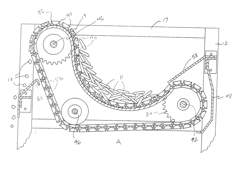
Referring to FIGS. 1 and 2 a product sizing
apparatus 10 includes a frame 12 having an input end~l4
and an output end 16. The frame 12 includes front legs
18 and rear legs 20 and end rails 15 and 17. Either set
of legs 18 or 20 may be made of telescoping members with
alignment holes and pins or the like for adjusting the
- 217~88
height of either the input end or the output end, thereby
controlling the angle of tilt of the frame 12. A motor
22 is attached to the frame and includes a chain housing
24. A longitudinal axis (provided for orientation) is
shown by the dash-dot line in FIG. 1.
The input end 14 of the apparatus 10 has a
scoop number 26 which receives the output of a conveyor
28 which carries product. Undersized pieces of product
are dropped into a receptacle 30 which sits below the
frame 12 to one side thereof. Properly sized product
drops from a chute 32 onto a conveyor 34 which removes
the product for further processing.
An endless web 36 is comprised of a plurality
of articulated slats 38 which are interconnected. Each
of the articulated slats 38 includes a plurality of oval
pockets 40 which serve as receptacles for undersized
pieces of product as will be explained below. The end-
less web is draped over a plurality of shafts (refer to
FIG. 3) including a drive shaft 42, a take-up shaft 44
and an idler shaft 46. The endless web is allowed to
hang from the shafts loosely thus forming a trough 37.
The drive shaft 42 is protected by a cover 48 connected
to the frame 12.
The drive shaft 42 is driven by a chain 49
connected to a sprocket 50 on the output shaft 52 of the
motor 22. The drive shaft 42 includes a sprocket 54
which engages chain links 56. Each of the articulated
slats 38 is supported on one of the chain links 56 at
each end of the frame. Additionally, there may be
sprockets on the drive shaft 42 and the take-up shaft 44
interspersed along the length of the shafts to engage
additional series of links (not shown) coupled to the
undersides of the slats 38.
The drive shaft 42 is oriented lower than the
take-up shaft 44. In order to keep product from falling
transversely off of the side of the frame supporting the
drive shaft, a guard deflector 58 is provided. At the
217~888
-
other side of the frame, a product deflector 60 is
provided to direct undersized pieces of product falling
out of the endless web 36 into the receptacle 30. The
operation of the invention with actual product 11 (for
example, carrots) is shown in FIG. 3A wherein the move-
ment of the endless web creates turbulence in the product
stream thus causing it to tumble from the input end 14 of
the frame 12 to the output end 16. Undersized pieces 13
of product 13 fall into the pockets 40 and are carried by
the endless web 36 which moves transversely to the longi-
tudinal axis of the frame and over one side of the frame.
As the articulated slats 38 turn over on the take-up
shaft 44 towards an angle greater than 90 from vertical,
the undersized pieces 13 of product 11 fall out of the
pockets 40 and are deflected by the deflector 60 into the
receptacle 30 below. The properly sized pieces of
product 11 which cannot enter the pockets 40 fall back
into the trough 37 formed by the endless web 36 and are
eventually carried downstream and deposited in the
conveyor 34.
Referring particularly to FIGS. 4, 4A and 4B,
each articulated slat 38 is mounted on a link 56, at
least at its distal ends. In each slat 38 pockets 40 are
formed which are oval in shape and which are oriented at
an angle to the long direction of the slat 38 which
extends substantially along the longitudinal axis of the
conveyor. As shown in FIG. 4B the pockets 40 have
rounded inner surfaces 41. The rounding of the inner
surfaces 41 ensures that undersized product does not
become wedged in the pockets 40 but falls out easily as
the web turns past horizontal as it moves around the
take-up shaft 44.
Several adjustments are possible which greatly
improve the efficiency and operation of the product sizer
described herein. Referring to FIG. 5, the take-up shaft
44 is mounted in a bearing block 47. There is a bearing
block 47 at each end of the separator and each bearing
2178888
block 47 is mounted to respective end rails 15 and 17 by
means of bolts 45. The bolts are inserted through a slot
(not shown) in the end rails 15 and 17 so that the
bearing block 47 may be moved back and forth along the
side rails in the directions shown by the arrow in
FIG. S. Moving the take-up shaft 44 in this way will
affect the steepness of the trough 37 formed by the end-
less web 36. The practical effect of this adjustment is
that the size distribution, efficiency and accuracy of
the separating operation will change. When the angle of
the trough is steep, only the smallest pieces will be
captured in the pockets 40 and deposited in the recep-
tacle 30. This means that the distribution curve illus-
trating the sizes of all pieces extracted from the
lS product stream will be shifted toward the smaller end and
will be a steeper curve. On the other hand, if the take-
up shaft is moved toward the outside of the frame 12
resulting in a shallower trough angle, larger product
pieces will be carried out of the product stream because
the flatter angle means there is less friction. The
distribution curve of the extracted pieces will shift
toward the larger sizes and will be somewhat flatter.
Another adjustment that may be made is in the tilt of the
frame. Either set of legs 18 or 20 may be made adjust-
able such as with telescoping members (not shown). Thetilt of the frame 12 will affect the processing speed of
the separator with a trade off in efficiency depending
upon the desires of the user.
The terms and expressions which have been
employed in the foregoing specification are used therein
as terms of description and not of limitation, and there
is no intention, in the use of such terms and expres-
sions, of excluding equivalents-of the features shown and
described or portions thereof, it being recognized that
the scope of the invention is defined and limited only by
the claims which follow.