Language selection

Search

Patent 2180269 Summary

Third-party information liability

Some of the information on this Web page has been provided by external sources. The Government of Canada is not responsible for the accuracy, reliability or currency of the information supplied by external sources. Users wishing to rely upon this information should consult directly with the source of the information. Content provided by external sources is not subject to official languages, privacy and accessibility requirements.

Claims and Abstract availability

Any discrepancies in the text and image of the Claims and Abstract are due to differing posting times. Text of the Claims and Abstract are posted:

  • At the time the application is open to public inspection;
  • At the time of issue of the patent (grant).
(12) Patent Application: (11) CA 2180269
(54) English Title: OVERFLOW PREVENTER
(54) French Title: OBTURATEUR POUR TROP-PLEIN
Status: Dead
Bibliographic Data
(51) International Patent Classification (IPC):
  • E03C 1/242 (2006.01)
(72) Inventors :
  • BLANEY, TREVOR (United Kingdom)
(73) Owners :
  • BLANEY, TREVOR (Not Available)
(71) Applicants :
  • LIFORMA INVESTMENTS N.V. (Monaco)
(74) Agent: OYEN WIGGS GREEN & MUTALA
(74) Associate agent:
(45) Issued:
(86) PCT Filing Date: 1995-01-04
(87) Open to Public Inspection: 1995-07-13
Availability of licence: N/A
(25) Language of filing: English

Patent Cooperation Treaty (PCT): Yes
(86) PCT Filing Number: PCT/GB1995/000007
(87) International Publication Number: WO1995/018896
(85) National Entry: 1996-06-28

(30) Application Priority Data:
Application No. Country/Territory Date
9400005.6 United Kingdom 1994-01-04
9413224.8 United Kingdom 1994-07-01

Abstracts

English Abstract


An overflow preventer comprising a plug receiv-
able in a drain hole and provided with a valve movable
between a first closed position and a second open posi-
tion, the valve being resiliently biased to the first position
while the pressure on the valve is less than a predeter-
mined value.


French Abstract

Ce dispositif pour trop-plein comprend un bouchon logeable dans un trou de vidange et pourvu d'une soupape susceptible de se déplacer d'une première position dans laquelle elle est fermée, vers une seconde position dans laquelle elle est ouverte, cette soupape étant sollicitée souplement vers sa première position lorsque la pression exercée sur elle est inférieure à une valeur prédéterminée.

Claims

Note: Claims are shown in the official language in which they were submitted.


CLAIMS:
1. An overflow preventer comprising a plus receivable
in a drain hole and provided with a valve movable between
a first closed position and a second open position, the
valve being resiliently biased to the first position
while the pressure on the valve is less than a
predetermined value.
2. A preventer as claimed in claim 1 wherein the
valve is resiliently biased by a spring.
3. A preventer as claimed in claim 2 wherein the
spring is a compression spring.
4. A preventer as claimed in any one of the preceding
claims wherein the valve is an annular valve.
5. A preventer as claimed in claim 4 wherein the plug
comprises the valve body with a circumferential valve
seat.
6. A preventer as claimed in claim 4 or claim 5
wherein the circumference of the valve is provided with
an O-ring for sealing on the seat of the valve body.
7. A preventer as claimed in any one of the preceding
claims wherein the plug is of resilient plastics
material.
8. A preventer as claimed in any one of the preceding
claims wherein the outer circumference of the plug is
provided with an O-ring to engage sealingly with the plug
hole.


11

9. An overflow preventer as claimed in any one of the
preceding claims having a specific rate of discharge of
at least 0.1 ms-1.

Description

Note: Descriptions are shown in the official language in which they were submitted.


-
21 80269
Wo 95/18896 r~

OVERFLOW ~; v t ~ l r ~

This invention relates to an overf low preventer
primarily but not exclusively for baths and sinks.
Baths and sinks may be provided with over10ws
which direct excess water to a drain. ~ The overflow may
however not be able to cope with the f low of water and
spillage may still occur.
GB 2 261 600 (Lewis) describes an overflow
preventer in which passage of water through a conduit
attached to the overflow causes the plug to be displaced
from the overflow. The al~.y~ t is very expensive to
make and f it . Furthermore when the preventer is actuated
its action is irreversible. This means that if a bath is
filled rather full and a ,bather displaces water 80 that
some passes through the overflow the device will be
actuated and unless reset all the water will drain from
the bath leaving the bather high and dry.
According to some "1r-~ts of the invention
there is provided an overflow preventer comprising a plug
receivable in a drain hole and provided with a valve
movable between a first closed position and a second open
position, the valve being resiliently biased to the first
position while the pressure on the valve is less than a
predetermined value.
~ he valve may be resiliently ~iased for example by

~ ` . 21 80269
Wo95/18896 2 r~1.......... 5

a spring su~h as a compression spring or a tension
spring .
The vaive may be a annuiar valve. A
circ-~mferential va~ve seat may be provided in the plus.
The valve may be provided with an O-ring for sealing on
t~e seat o~ t~e valve hody. The plus may compri~2
resilient plastics material. The outer ci~c~amference may
be provided wlth an O-ring to engage seaiingly with the
pluy hole.
FTho~ir~nts of the invention will be illustrated
by way of example on~y by reference to the ~ nying
figures of which:
Figure 1 is a top plan of an ~mho~l i t of the
invention;
Figure 2 is a side view of the pIug body of the
embodiment of Figure l;
Fi~ure 3 is a plan of a valve of the embodiment of
Figure 1;
Figure 4 is a side elevation of the va~ve of
Figure l;
Figure ~ is an enlarged scr~p cross-sectional view
of the preventer of the first embodiment;
Figure 6 is a top plan of a second embodiment;
Figure 7 is a side elevation of the second
embo~iment;
Figure ~ is a cross sectional view of the seconfi

21 80269
WO 95118896 P~l, ~,_,'.1 /


embodiment, and
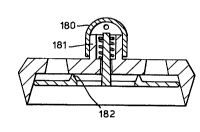
Figure g is a cross-section of a urther
embodiment .
The embodiment of E'igures 1 to 5 is intended as a
replaceme~Lt for a bath or sink plug. In general a cord
or chain or other fastener (not shown) secures the device to
the bath or sink in each illustrated ~mhQr1; L. This is not
essential and oy way o~ example the preventer may be
fitted to an auxiliary drain and thus a separate plug and
plug hole could still be required. The preventer may
additionally be fitted to conventional over10ws. This
could have the advantage of preventing spiders crawling
through the overflow and into the bath to the possible
horror or in some cases danger of the user. In
Australia and some other parts o~ the world conventional
overf lows are not f itted because o the danger of
venomous spiders living in the overflow. Since the
preventor of the invention is closed in the rest position
any spider living in the over10w is unl ikely to be able
' o escape into the bath of a user. The embodiment
therefore has a body ~1~ or reception in or over the plug hole
Conveniently the body comprises a plastics material.
Preerably the plastics has a degree o resilience to
assist in iorming a watertight fit to the plu~ hole.
Fitting may also be facilitated by providing a tapered
portion t2 ~ on the body. Preferably the taper i5 in the


~ ~ 2 1 ~0269
Wo9S/18896 1~ ,,, 5


range 5 to 10 preferaoly 7 to 9 especially a~out 8.
his may also allow a prever.ter to be fittec to a range
of different sizes of plug hole. It may be desirable to
provide an O-rin~ ~not shown) received in a peripheral
groove of the body ( 1 ) to provide even better sealing.
As can be seen from ~igure l conduits (3) are provided in
the body which communicate with the valve to be descri~ed
hereinafter. In the illustrated embodiment the conduits
are on the top face of the body but they could be
provided on the side although a less compact device might
result . Preferably the conduit ' s area is ahout 20% or
25% to 60% more preferably 30 to 50% of the area of t~e
top face area of the preventer. I~ the area is too low
then drainage may prove too slow and also BSI
(British Standard Institute) rP --~tions may not be
complied with. If much greater than about 60% the top
face may be too weak. The precise area is not however o~
the essence of the invention.
A lip (6) is provided in the body and as described
hereinafter this acts as a valve seat in the
i 1 lustrated P~nho~ i t .
A valve ( 7 ) is provided . In the embodiment
described it comprises a disc preferably of plastics
material especially resilient plastlcs material. An 0-
ring ( 8 ) may be provided in the circumference to form a
good seal with the seat ( 6 ~ . Where the valve is of or


21 80269
Wo 95/18896
s

coated with resilient material a good seal may be
obtalned without an O-~ing. Alter~.atively or Qddl~ionally
an O-ring may be provided on the seat in the rest position
the valve ( 7 ) is biased against the valve seat ( 6 ) to
form a seal. When the bath is filled with ~ate- t~e
pressure on the valve increases. Tf filling is continued
the pressure on the valve (7) will overcome the bias and
urge the valve (7) off the valve seat (6~. The valve
will then move for example to the position shown in
ghosted lines in Figure 5 . The conduit ( 3 ) will then
be open and excess water wi l l run away to waste . When
supply of -~ater to the bath stops water Will drain away
until the pressure of water no longer overcomes the bias.
The bias will then urge the valve ~7) back to the seat
( 6 ) and prevent further f low . The valve member ( 7 ) of
this embodiment is broadly wheel-shaped having an outer
rim (30) connected to the valve rod (10) by three
peripheral spokes (31). When the valve is in the no load
position the peripheral area is sealed by the rim
engaging the lip . The valve rod guide ( 12 ) overlies the
gaps in the valve ( 7 ) def ined by the rim ( 30 ) and spokes
( 31 ) preventing escape of water in the no load position .
When actuated water escapes not only around the rim by
also through the gaps defined by the rim and spokes.
This allows a high volume of water to pass through the
valve when actuated.


~ `~ . 21 80269 ~
WO 95118896 r~


The preferred bias is a spring ~9~ but this is not
essential for the performance of the invention. In the
lllu~rate~ emDodlments the valve depends from a va ve
rod ~10 ) . In the preferred embodiment the valYe rod ( 10 )
is received in a valve rod guide ( 12 ) which in
combination with legs (11) of the body (ll define conduit
openings ( 3 ~
A spring ( g ) is received over the valve rod and
held in position for examp~e by a clip ( 13 l . Spring
production is now a well understood art and the
production of springs o~ the desired strength is
relatively straightforward. ~t may not therefore be
necessary to provide an adjuster to adjust the force
produced by the spring. The valve is preferably a pop
valve which stays closed unti~ the pressure exceeds an
operating valRe and then opens widely. By appropriate
spring selection this should be readily ac~ievable.
An embodiment of Figs . 1 to a was subj ect to a
test which the drain hole of a bath was 0 . 685m above an open
discharge. The temperature was 20C. The device was
seemed into the drain hole. The conduit area of the body
was 555.26 mm2. The plan areas of the top of the body
was about 316amm2. As the base and valve separated an
additionai gap of 125 . 68 mm2 per mm drop was created A
spring opening at 0.023 m ~9") was selected and the rate
of .~ater ~lo~sing into the bath adjusted until a steady


21 80269
Wo 95/18896 ~ ~ r ~ . ~
slrike was achievec. This was found to be
m3S~i ( 5 . S . UK gals/min) .
The specific rate of discharge was thereiore about
0.13 ms~l. It is preferred that the specific rate of
discharge under the above conditions be at ieast 0 . l ms~
preferably at least 0.125 m5l still more preferably at
least 0.175 msl and yet more preferably, a,t least 0.2 ms
even more preferably at least 0.25 msl. The specifi~
rate of discharge is important. If it is too low then a
large device will be nPrP~s~ry to pa~s sufficient water.
A high specific rate of discharge can be obtained by
providing both the body and valve with holes which are
closed when the valve is in the rest position and open
when the valve is activated. This can be achieved by
overlying solid portions of the body over conduit
portions of the valve and vice versa.
It is preferred that the open area increase as the
valve moves further away from its rest position since
the e~ficiency will then increase with rate of discharge.
In the event that water passes through a
conventional overflow to discharge a primitive pump or
suction actio~ may still further increase the devices
ef f iciency .
If desired a cover (not shown) may be provided
over the valve rod and spring.
Modiflcations to the invention will be apparent to

- 2 1 ~0269
Wo 95/18896 P~ l. . /


workers skilled in the art. FQr example in the secon~
;ilustrated e~bodiment a plurality of cy~in~-lc~: ~Loles
( 14 ) are formed in the body ( 1 ) . The face of the valve
( 7 ) has a resilient coating ~15 ) for example of rubber
to improve sealing with the valve seat. When the water
pressure on the valve ( 7 ) exceeds the biasing iorce of
the spring ( 9 ) the excess water escapes around the edge
of the valve and through rh;~nn~l c ( 16 ) where provided.
The biasir~g force provided by the spring can be adj usted
by moving a nut (17) bearing on a washer (lg) on the
threaded portion of the valve rod ( 10 ) . A cover ( 18 ) is
provided on the body ( 1 ) over the valve rod and spr~ ng .
In the third embodiment of the invention
illustrated in Figure 9 the device is provided with cover
( 180 ) . Cover ( 180 ) is provided with a coatiny of thermal
changing materiz~l. For example a liquid crystal materi~l
changing to red at a temperature of about 50C may be
provided. Where present the thermal colour changing
material provides a warning of excessive water
temperature. If the cover ( 180 ) is transparent or
translucent the colour changing material can be present
on the inside of the cover and thus be relatively
resistant to wear.
The cover ( 180 ) can be an interference fit on a
preferably cylindrical upstand (181) provided on the boay.
If this is done the cover (180) may be of resilient

.

1 83269
Wo 95/18896 ~l,. /


material which can be slipped over the upstand. A fixing
cahin or cord carried on the cover may be provided to
secu-e t~he de~ ce to the bath or sink.
In some embodiments of the invention as for
example that shown in Figure 9 a seal is provided on the
face of the valve abutting the body., The seal can
comprise a raised circular resilient member (182) formed in
either or both the valve or the body. This seal serves to reduce
1 eakage .
It may be desirable to provide a draft angle on ~ _
the cavities of valve or body. This serves to
facilitate moulding if the device is made of plastics and
may also increase thluu~ u~.
Although the invention has been discussed by
reference to baths it will be apparent that it has
uti~ity ~l cc~wh~re notably in basins and cisterns. The
skilled will have no difficulty in altering the biasing
force to provide the desired maximum depth before the
preventer actuates.


Representative Drawing
A single figure which represents the drawing illustrating the invention.
Administrative Status

For a clearer understanding of the status of the application/patent presented on this page, the site Disclaimer , as well as the definitions for Patent , Administrative Status , Maintenance Fee  and Payment History  should be consulted.

Administrative Status

Title Date
Forecasted Issue Date Unavailable
(86) PCT Filing Date 1995-01-04
(87) PCT Publication Date 1995-07-13
(85) National Entry 1996-06-28
Dead Application 2003-01-06

Abandonment History

Abandonment Date Reason Reinstatement Date
1999-01-04 FAILURE TO PAY APPLICATION MAINTENANCE FEE 1999-08-09
2000-01-04 FAILURE TO PAY APPLICATION MAINTENANCE FEE 2000-01-07
2002-01-04 FAILURE TO PAY APPLICATION MAINTENANCE FEE
2002-01-04 FAILURE TO REQUEST EXAMINATION

Payment History

Fee Type Anniversary Year Due Date Amount Paid Paid Date
Application Fee $0.00 1996-06-28
Maintenance Fee - Application - New Act 2 1997-01-06 $50.00 1996-11-29
Maintenance Fee - Application - New Act 3 1998-01-05 $50.00 1997-12-10
Reinstatement: Failure to Pay Application Maintenance Fees $200.00 1999-08-09
Maintenance Fee - Application - New Act 4 1999-01-04 $50.00 1999-08-09
Reinstatement: Failure to Pay Application Maintenance Fees $200.00 2000-01-07
Maintenance Fee - Application - New Act 5 2000-01-04 $75.00 2000-01-07
Maintenance Fee - Application - New Act 6 2001-01-04 $75.00 2000-12-20
Owners on Record

Note: Records showing the ownership history in alphabetical order.

Current Owners on Record
BLANEY, TREVOR
Past Owners on Record
None
Past Owners that do not appear in the "Owners on Record" listing will appear in other documentation within the application.
Documents

To view selected files, please enter reCAPTCHA code :


To view images, click a link in the Document Description column. To download the documents, select one or more checkboxes in the first column and then click the "Download Selected in PDF format (Zip Archive)" or the "Download Selected as Single PDF" button.

List of published and non-published patent-specific documents on the CPD .

If you have any difficulty accessing content, you can call the Client Service Centre at 1-866-997-1936 or send them an e-mail at CIPO Client Service Centre.


Document
Description 
Date
(yyyy-mm-dd) 
Number of pages   Size of Image (KB) 
Representative Drawing 1997-06-25 1 3
Cover Page 1996-10-04 1 11
Abstract 1995-07-13 1 30
Description 1995-07-13 9 205
Claims 1995-07-13 2 25
Drawings 1995-07-13 3 32
International Preliminary Examination Report 1996-06-28 11 320
Office Letter 1996-08-13 1 20
Fees 1996-11-29 1 60