Language selection

Search

Patent 2180489 Summary

Third-party information liability

Some of the information on this Web page has been provided by external sources. The Government of Canada is not responsible for the accuracy, reliability or currency of the information supplied by external sources. Users wishing to rely upon this information should consult directly with the source of the information. Content provided by external sources is not subject to official languages, privacy and accessibility requirements.

Claims and Abstract availability

Any discrepancies in the text and image of the Claims and Abstract are due to differing posting times. Text of the Claims and Abstract are posted:

  • At the time the application is open to public inspection;
  • At the time of issue of the patent (grant).
(12) Patent Application: (11) CA 2180489
(54) English Title: ELECTRICAL CONNECTOR
(54) French Title: CONNECTEUR ELECTRIQUE
Status: Dead
Bibliographic Data
(51) International Patent Classification (IPC):
  • H01R 13/648 (2006.01)
  • H01R 13/658 (2011.01)
  • H01R 13/658 (2006.01)
  • H01R 12/16 (2006.01)
(72) Inventors :
  • HARTING, DIETMAR (Germany)
  • PAPE, GUNTER (Germany)
  • BERGHORN, MANFRED (Germany)
(73) Owners :
  • HARTING ELEKTRONIK GMBH (Germany)
(71) Applicants :
(74) Agent: MARKS & CLERK
(74) Associate agent:
(45) Issued:
(22) Filed Date: 1996-07-04
(41) Open to Public Inspection: 1997-01-08
Examination requested: 1996-09-18
Availability of licence: N/A
(25) Language of filing: English

Patent Cooperation Treaty (PCT): No

(30) Application Priority Data:
Application No. Country/Territory Date
195 24 809.0 Germany 1995-07-07

Abstracts

English Abstract


For an electrical connector for assembly on printed-circuit boards, having a
housing which contains and screens contact elements it is provided that the
housing is manufactured as an injection-moulded part with integrally formed
pins. When the connector is assembled on the printed-circuit board, the
pins engage into plated holes and the electrical connection of the housing to
the printed-circuit board is effected by soldering the pins or by means of a
press-in portion formed on the pins.


Claims

Note: Claims are shown in the official language in which they were submitted.


Claims
1. Electrical connector for assembly on printed-circuit boards, having a
single- or multi-part housing which contains and screens contact ele-
ments of the connector, and haYing means of connecting the housing
in an electrically conductive manner to the printed-circuit board, char-
acterized in
that the housing (1) takes the form of an injection-moulded part and is
electrically conductive, and
that pins (9) integrally formed on the side (4) of the housing (1) di-
rected towards the printed-circuit board are provided, which are in-
sertable into holes of the printed-circuit board and connectable to
printed conductors of the printed-circuit board.
2. Electrical connector according to claim 1, characterized in
that the housing (1) is made of a metal material, preferably of a high-
purity zinc casting alloy.
3. Electrical connector according to claim 1, characterized in
that the housing (1) is made of plastic material and provided with a
conductive coating.
4. Electrical connector according to one of the preceding claims, charac-
terized in
that the pins (9) take the form of solder pins.


5. Electrical connector according to one of claims 1 to 3, characterized in
that the pins (9) are provided with a press-in zone (10) which, upon
pressing of the pins into the holes of the printed-circuit board, comes
into contact with a hole plating.

Description

Note: Descriptions are shown in the official language in which they were submitted.


` 1 21 80489


Electrical connector
The invention relates to an electrical connector for assembly on printed-
circuit boards, having a single- or multi-part housing which contains and
o screens contact elements of the connector, and having means of connectingthe housing in an ele.,~ "y conductive manner to the printed-circuit board.
Such co,~,~eulu, ~, particularly when they are provided with coaxial contacts,
have to have a screen in order to prevent extemal disturbing pulses from
reaching the contact elements inside the u~ eulol and to prevent outward
emission of pulses which are carried through the contact elements.
It is known to provide electrical w, " ,e,.lu~ ~ with a conductive housing, which
contains the contact elements and is used to retain and screen said contact
elements. The contact elements comprise solder pins or press-in pins,
which project from one side of the housing and are insertable into holes of a
printed-circuit board. For the electrically conductive cu""eulioll of the
housing to the printed-circuit board, a sheet metal part is provided which is
fastened (riveted) to the housing and uu~ Jrises pins which are insertable
into plated holes of the printed-circuit board. In said case, however, manu-
facture of another component in addition to the housing is required.
The object of the invention is to construct an electrical co",~lu, of the type
described initially in such a way that it may be manufactured inexpensively.
_ .
Said object is achieved in that the housing takes the form of an injection-
moulded part and is electrically conductive, and that pins integrally formed
on the side of the housing ~acing the printed-circuit board are provided,

2 1 $0489
2
which are insertable into holes of the printed-circuit board and connectable
to printed conductors of the printed-circuit board.
Advantageous, tri~lel1 le~ of the inYention are indicated in claims 2 to 5.
The advantages achieved by the invention are in particular that, by virtue of
integrally forming the solder or press-in pins on the housing preferably
manufactured as an injection-moulded part, there is no need for an addi-
tional cu" ,~ e"~ for e ,ld~l;sl li~)g the electrical connection of the housing to
o the printed-circuit board. In said respect, a further advantage is that contact-
ing problems (contact resistance of co,~,~e~iol1 points) between the connec-
tion of the additional c~",pu,)e"l to the housing are also eliminated.
A further advantage, given the use of a high-purity zinc casting alloy as a
housing material, is that said material has an excellent electric conductivity
and so a reduction of the electrical housing It:si~la~ is achieved.
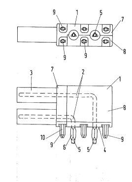
An embodiment of the invention is illustrated in the drawings and described
below in detail.

The drawings show:
Fig. 1 a view of a connector,
Fig. 2 the side view of the connector according to Fig. 1, and
Fig. 3 the bottom view of the connector according to Fig. 1.
The connector illustrated in Figs. 1 to 3 substantially comprises a housing 1,
in which contact elements 2 are held. The contact elements take the form of
coaxial contacts and, at the left side of the connector, tubular screening
sleeves 3 are disposed over the contact elements and fastened conductively
in or to the housing. Projecting from the underside 4, i.e. from the side of the

2 1 804~9
3
housin3 directed towards the printed-circuit board, are terminals 5 of the
contact elements. Said terminals are provided with a press-in portion 6
which may be pressed into holes of a printed-circuit board which is not
shown in detail here.
s

The housing 1 of the connector is preferably made of a high-purity zinccasting alloy such as, for example, GD-ZnAi4Cu1 according to DIN 1743,
Part 2, and comprises two half shells 7, 8. The contact elements 2 are held
in said housing by means of spacers made of insulating material, which are
~o not shown in detail here. The housing or the half shells are manufactured as
injection-moulded parts and are provided at the underside with integrally
fonmed pins 9. The pins, which during assembly of the ~or,,~e~ul on the
printed-circuit board engage into plated holes, take the form of solder or
press-in pins, the press-in pins being provided with a press-in portion 10.
The press-in portion may comprise a rigid or, optionally, elastic press-in
zone.
The housing or the half shells may optionally be made of plastic material and
provided with a conductive coating - metallic coating.
Representative Drawing
A single figure which represents the drawing illustrating the invention.
Administrative Status

For a clearer understanding of the status of the application/patent presented on this page, the site Disclaimer , as well as the definitions for Patent , Administrative Status , Maintenance Fee  and Payment History  should be consulted.

Administrative Status

Title Date
Forecasted Issue Date Unavailable
(22) Filed 1996-07-04
Examination Requested 1996-09-18
(41) Open to Public Inspection 1997-01-08
Dead Application 2000-07-04

Abandonment History

Abandonment Date Reason Reinstatement Date
1999-07-05 FAILURE TO PAY APPLICATION MAINTENANCE FEE

Payment History

Fee Type Anniversary Year Due Date Amount Paid Paid Date
Application Fee $0.00 1996-07-04
Request for Examination $400.00 1996-09-18
Registration of a document - section 124 $0.00 1997-01-23
Maintenance Fee - Application - New Act 2 1998-07-06 $100.00 1998-06-11
Owners on Record

Note: Records showing the ownership history in alphabetical order.

Current Owners on Record
HARTING ELEKTRONIK GMBH
Past Owners on Record
BERGHORN, MANFRED
HARTING, DIETMAR
PAPE, GUNTER
Past Owners that do not appear in the "Owners on Record" listing will appear in other documentation within the application.
Documents

To view selected files, please enter reCAPTCHA code :


To view images, click a link in the Document Description column. To download the documents, select one or more checkboxes in the first column and then click the "Download Selected in PDF format (Zip Archive)" or the "Download Selected as Single PDF" button.

List of published and non-published patent-specific documents on the CPD .

If you have any difficulty accessing content, you can call the Client Service Centre at 1-866-997-1936 or send them an e-mail at CIPO Client Service Centre.


Document
Description 
Date
(yyyy-mm-dd) 
Number of pages   Size of Image (KB) 
Abstract 1996-10-09 1 10
Cover Page 1996-10-09 1 14
Claims 1996-10-09 2 24
Drawings 1996-10-09 1 11
Description 1996-10-09 3 76
Representative Drawing 1997-08-21 1 7
Assignment 1996-07-04 7 224
Prosecution-Amendment 1996-09-18 3 113