Note: Descriptions are shown in the official language in which they were submitted.
~~8~88t
TITLE OF THE INVENTION
PACKER TYPE GROUNDWATER SAMPLING SYSTEM AND WATER
SAMPLING METHOD
BACKGROUND OF THEINVENTION
The present invention relates to a packer type
groundwater sampling system, which can be used for an
apparatus for sampling groundwater in a borehole or a well
or for an apparatus for carrying out test at any desired
depth in a borehole or a well. The invention also relates
to a method for sampling groundwater using such a system.
Continuous water sampling method has been used for -
sampling groundwater in the past. A typical method is a
pumping-up method. In this method, a pump is installed in a
probe placed in a borehole, and groundwater in a water
sampling section is continuously sampled and brought up to
the ground surface. Also,- an air-lift method using air
pressure from ground surface is known as one of the
continuous water sampling methods.
On the other hand, a batch style water sampling method
has also been proposed (Japanese Utility Model Publication
Laid-Open 3-69090 and Japanese Patent Publication Laid-Open
6-201542). In this method, a completely sealed water
sampling container is used to characterize groundwater
chemistry and water can be sampled under in-situ condition.
Also, a water sampling apparatus has been proposed,
which-combines the above two methods to overcome the _. _._.
1
1
disadvantages of these methods (Japanese Patent Publication
Laid-Open 6-I93I01).
The pumping-up method, i.e. the most typical of the
continuous water sampling methods, is higher in working
efficiency than the batch style water sampling method.
However, because pumping ability of the pump is effective
for tha depth of several hundreds of meters in the current
technical level, water cannot be pumped up if the
groundwater level in borehole is lower than the limit of the
pumping ability.
Also, because it is impossible to sample groundwater
under in-situ condition from structural reason, there are
problems in that dissolved gas in the groundwater is
released at the ground surface when it is opened to the
15- atmospheric air due to pressure change. Further, because
Water is sampled continuously for lpng time, load applied on
the pump is high, and this extensively reduces durability of
the-pump.
In the air-lift method, compressed air sent from the
ground surface is used, and it is impossible to sample
groundwater in in-situ condition.
By the batch style water sampling method, it is
possible to sample formation water under in-situ condition
without disturbing geological environment where the
groundwater is present. However, it is not possible to
strictly judge whether the formation water under in-situ
condition has been sampled or not unless there is the
function to confirm that the pressure in the container for
2
sampling groundwater has reached the same level as the
underground condition.
Also, in the practical procedure, drilling fluid has
been used for the drilling of boreholea and the groundwater
will be contaminated by this fluid. The absence of drilling
fluid in water has been checked by continuous monitoring of:
(1) concentration of tracers (e.g.,Uranine dye or Li) which
are introduced into the drilling fluid; and
(2) concentration of chemical components.
The absence oftracers, or constant concentrations of
chemical components can be regarded as an indication of the
absence of drilling fluid. Water sampling volume per batch
is also low, and much time is required to carry out the work
by this method alone, and there is also problems in working
efficiency.
On the other hand, the combination of the continuous
water sampling method and the batch style water sampling
method is not yet used in practical application, but it
overcomes the disadvantages of these two methods. By this
method, however, formation water necessary for water quality
analysis is sampled by one time in the batch style water
sampling method. If the required quantity has not been
sampled, the water sampling section is sealed off for once
and=the water is mixed with the groundwater of the other
level when the second batch style water sampling is carried
out: Thus, the continuous water sampling must be carried
out again. Further, in case water chemistry is to be
monitored over a long period, the continuous water sampling
3
2 ~~8~i88 i
and the batch style water sampling must be performed each
time, and problems arise about quality or economic
feasibility of the sampled groundwater. Also, there are
problems in that the formation water sampled and brought to
ground surface by the batch style water sampling method
cannot be easily taken out and transported.
In testers in a borehole, there are hydrological
tester, pore water pressure measuring apparatus, flow
direction and velocity measuring apparatus, borehole
expansion tester, etc. in addition to groundwater sampler.
In major functions of these apparatuses, there are the
following problems at present:
(a) Packer structure
The tester.in the borehole normally uses packer or -
mechanical packer based on water pressure or air
pressure to set up a measuring section. As depth becomes
deeper, water packer is used because of safety and
maneuverability. In the conventional type water packer
structure, there are the following problems:
- Because diameter of water supply hose in the packer
expansion system is small, pressure loss inside the
pipe increases, and longer time is required for
expansion of the packer.
- To expand the packer, water inhose (such as tap
water), and not in-hole water (i.e. mixture of
groundwater at various depths in a borehole), is
used in many methods. In this-case, if leakage
occur, water other than the in-hole water is
4
~~ ~ 8Q88~
brought into the hole, and this results in
contamination of the groundwater in the borehole.
- When the level of groundwater.in borehole is
lowered, packer is spontaneously expanded due to
water pressure from ground surface to the level of
groundwater. As a result, it is difficult to recover
the packer.
(b) Installation of pipes and signal cable
- In many cases, water supply hose of the packer
expansion system is installed outside casing pipe.
This causes damage of wall of borehole and makes it
difficult to recover the apparatus. Also, much
time is required for installing hoses and cables,
leading to lower working efficiency.
- Because water hose is present in a packer expansion
circuit system, ~rolume inside the hose and volume
change due to creeping of hose are also included in
water injection quantity, and it is not possible to
accurately identify quantity of water injected into
the packer itself.
Also, it is difficult to identify quantity of the
water extracted from the packer.
To solve the above problems, it is an object of the
present invention to develop and provide a water sampling
system, by which itis possible to sample formation water
under in-situ condition at deeper depth reliably,
efficiently and economically without disturbing geological
5
~~8~88i
environment of groundwater present in underground formation
by means of borehole.
It is another object of the present invention to limit
a water sampling section to a certain depth, to quickly
discharge drilling water and other.water mixed with water of
theother level from the sampling section and to replace
them with the formation water.
It is still another object of the present invention to
sample the formation water under in-situ condition.
It is another object of the present invention to
sample the formation water by batch style water sampling
method continuously and by many times without carrying out
continuous water sampling after the-groundwater in the water
sampling section has been replaced with the formation water_
It is another object of the preeent invention to make
it possible to confirm that pressure in a water sampling
container is in equilibrium with water pressure environment
where the formation wai=er has been present in the batch
style water sampling method and to confirm water sampling
volume in the water sampling container in order to reliably
perform water sampling under in-situ condition.
It is still another object of the present invention to
make it possible to easily take out formation water sampled
and brought to ground surface by the batch style water
sampling method and to transport the water under in-situ
condition.
It is another object of the present invention to make
the packer expandable b:y utilizing in-hole water in order to
6
~t80881
reliably and safely limit the water sampling section without
disturbing the geological environment where the groundwater
is present_
It is still another object ofthe present invention to
make it possible to sample and bring groundwater safely to
ground surface by protecting major functional components
even when it is not possible to recover the packer system
due to collapse occurred in the borehole_
SUI~fARY OF THE INVENTION
The packer type groundwater sampling system according
to the present invention comprises a casing pipe, where a
packer system having an upper packer and a lower packer with
a water sampling filter placed therebetween is installed at
the tip thereof, a downhole system comprising a connecting
unit, a water sampling unit and a water pumping unit,
inserted into the casing pipe and connected with said packer
system by the connecting unit, and a control unit installed
on ground surface and used for controlling the downhole
system, whereby said connecting unit has a water sampling
section circuit with a pore water pressure gauge connected
thereto and a water circuit switching valve for switching
over a packer circuit with a packer pressure gauge
connected therewith, said water sampling unit has a water
sampling container where a line from the water circuit
switching valve of the connecting unit and the pressure in a
water sampling container gauge are connected, and said water
pumping unit has a water circuit switching valve connected
7
218Q88i
to a line from the water circuit switching valve of the
connecting unit and has a water circuit switching valve used
for switching over the line from the connecting unit to
ground surface or to the hole and a'pump, which can be
switched over fn two directions by,a pump switching valve.
The present invention is characterized in that the
connecting unit comprises a tapered portion being at
symmetrical position of t 180° at its tip and having a key
groove to connect a guide key mounted on the casing pipe at
its tip, and when the downhole system is inserted and when
said tapered portion and the guide key are brought into
contact, the connecting unit is rotated along the tapered
portion until the guide key is engaged in the key groove.
The present invention is also characterized in that a
range finder for measuring the distance from the
packer system is provided at the tip of the connecting unit.
The packer type groundwater sampling method of the
present invention comprises a step for installing a
casing pipe in a borehole, said casing pipe having a
packer system consisting of an upper packer and a lower
packer with a water sampling filter placed therebetween
and being installed at its tip, a step for inserting
a downhole system into the casing pipe and for connecting it
to the packer system by a connecting part, said downhole
system comprising a connecting unit having
a watercircuit switching valve for switching over a
water sampling section circuit where:a pore water
pressure gauge is connected and a packer circuit, the
8
~~~~~ss~
water circuit-switching valve of the connecting unit,
and a water pumping unit having a pump connected to a
line from the water circuit switching valve from the
connecting unit and having a water. circuit switching valve
to switch over the line from the connecting unit to ground
surface or to downhole unit and a pump, which can be
switched over in two directions by a pump switching valve, a
step for switching over the water circuit switching valve of
theconnecting unit to the packer circuit, for selecting the
water circuit switching valve of the water pumping unit to
ground surface-or to downhole unit and for setting the water
sampling section by increasing packer pressure to a
predetermined value by~ the pump and by e~anding the upper
and the lower packers, a step for switching over the water
circuit switching valve of the connecting unit to the water
sampling section circuit, for selecting the water circuit
switching valve of the water pumping unit to ground surface
or to downhole unit and for continuously sampling water
until the water sampling section is filled with formation
water by operating the pump in water pumping direction, a
step for stopping the pump when it is judged that in-hole
water in the water sampling section has been replaced with
the formation water and for closing valves of the water
pumping unit and the connecting unit, and a step for
sampling water by continuous water sampling using the water
pumping unit or.by the batch style water sampling using the
water sampling unit.
9
t ~1'~8Q88 ~
Also, the present invention is characterized in that
expanded conditions of the upper packer and the lower packer
are maintained and water sampling in the same water sampling
section is repeatedly performed by moving the downhole
system up and down.
The system of the present invention is capable to
sample groundwater present in deep geological formation in a
borehole in reliable, safe and efficient manner without
disturbing environment.
The method for sampling groundwater according to the
present invention comprises two processes, i.e. a continuous
water sampling process using pumping-up for continuously and
efficiently sampling groundwater and a batch style water
sampling process for confirming the same environment as that
of groundwater in underground layer. and forsampling
formation water, whereby the formation water after removing
drilling water by the continuous water sampling process can
be repeatedly sampled as necessary, and the water sampling
container can be easily removed and transported.
The downhole system based on the continuous water
sampling method and th.e batch style water sampling method is
designed in such structure that it can be inserted into or
removed from a packer system in the hole by moving it within
a casing pipe, and the downhole system serving as a main -
functioning unit can be safely collected and recovered even
when tha packer system cannot be recovered due to collapse
in the hole. When inserting or removing it, a self-removing
closed coupler is used in the packer in the hole and in the
~~~c~~s~
circuit of water sampling section, and leakage of the packer
water does not occur or groundwater in the water sampling
section is not contaminated.
Still other objects and advantages of the invention
will in part be obvious and will in part be apparent from
the specification.
The invention accordingly comprises the features of
construction, combinations of elements, and arrangement of
parts which will be exemplified in the construction
hereinafter set forth, and the scope of the invention will
be indicated in the claims.
BRIEF DESCRIPTION OF THE DRAWINGS
Fig. 1 shows an overall arrangement of a system
according to the present invention;
Fig. 2 shows an arrangement of a downhole system;
Fig. 3 shows an arrangement of a water sampling unit;
Fig. 4 shows a batch style water sampling mechanism of
the water sampling unit;
Fig. 5 shows insertion of the downhole system;
Fig. 6 represents drawings for explaining the tip of a
connecting unit;
Fig. 7 represents drawings for explaining the downhole
system and a packer system;
Fig. 8 represents drawings for explaining a connecting
coupler;
Fig. 9 shows a continuous water sampling circuit;
Fig. 10 shows a batch style water sampling circuit;
11
Fig. 11 is a diagram showing calculation examples of
water sampling volume based on initial pressure of a
water sampling container and pressure in a water sampling
container;
Fig. 12 is a diagram showing an example of
observation data in a continuous water sampling test;
Fig. I3 is a diagram for explaining working efficiency
in the continuous water sampling method;
Fig. 14 shows an example of observation data during
1D batch style water sampling period;
Fig. 15 is a diagram showing an example of observation
of packer and pore water pressure changes with respect to
the number of insertions and removals when the downhole
system is repeatedly inserted and removed;
Fig. 16 is a diagram showing an example of observation
results from insertion of the downhole system to its
connection with the packer system in the hole;
Fig. 17 shows an example of observation data when
packers are expanded;
Fig. 18 shows relationship between continuously
sampled water quantity and electric conductivity;
Fig. 19 explains improvement of working efficiency in
continuous water sampling; and
Fig. 20 shows water sampling volume by the batch style
water sampling.
DETAILED DESCRIPTION OF THE PREFERRED EMBODIMENT
In the following, description will be given on an
12
~'~ ~~88 ~
embodiment of the present invention referring to the
drawings.
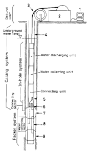
Fig. 1 shows an overall arrangement of a system
according to the present invention.
The groundwater sampling system of the present
invention comprises a surface unit, a casing system, a
packer system and a downhole system.
In a borehole formed by drilling, there is provided a
casing pipe 4 where a plurality of pipes are connected by
screw connection and the number of connected pipes is
increased to extend the pipes to a given depth. This is
used for in-hole installation of the packer system and for
protection of the downhole system when it is moved up and
down. This arrangement is called a casing system.
At the tip of the casing pipe 4, an upper packer 7 and
a lower packer 9 made of natural rubber and communicated
with a connecting pipe are mounted by screw connection. By
pouring or sampling water-through a pump of a water pumping
unit, the packers are expanded or compressed, thus shielding
and limiting water sampling section. A water sampling
filter 8 for dust prevention is installed between the
packers to prevent suspended solids and precipitates in the
water sampling sectionfrom entering the downhole system.
These components constitute the packer system. On top of
the=packer system, the downhole system is connected, which
comprises a water pumping unit, a water sampling unit and a
connecting unit suspended from the surface unit by a
composite cable 3. The details of connection between the
13
218088
downhole system and the packer system will be described
later. When the downhole system is moved down, a tapered
portion installed at ,symmetrical position of t 180° on outer
periphery of the pipe of the connecting unit is brought into
contact with a guide key 5 of the casing pipe 4. Then, the
downhole system is rotated along the tapered portion until
the-guide key 5 is engaged in a key groove at tapered end,
thus fixing the position and connecting the two components.
In this case, concave and convex connecting couplers 6 are -:
engaged with each other, and a packer circuit and a water
sampling circuit are formed. (The details are to be
described later.)
The surface unit comprises a water circuit hose, an
optical fiber cable for communication, a cable winding unit
2 used for delivering and winding up the composite cable 3
incorporated with power supply line used for moving the
downhole system up and down, and a control and communication
unit for controlling t:he downhole system and for monitoring
communication data.
By the system arrangement as described above, the upper
packer 7 and the lower packer 9 are. expanded by the control
from the surface unit to limit the water sampling section in
theborehole. Drilling wateror mixed water from the other
level present in the section are discharged to ground
surface or to the place beyond the water sampling section by
the pump in the water pumping unit and are quickly replaced
with formation water. After the groundwater in the water
sampling section has been replaced with the formation water,
14
~~'~0~8 t
the formation water in in-situ condition is moved and
sampled and brought to ground surface by a perfectly sealed
water sampling container (500 ec) incorporated in the water
sampling unit.
Next, description will be given on each of the units in
the downhole system referring to Fig. 2.
The water pumping unit is incorporated with the
pump 11 having water suction and discharge functions and
controls the packer and performs continuous water sampling.
A control amplifier 10 controls the packers and operation of
a water circuit switching valve 13_.and the pump 11 when
continuous water sampling is performed, and it also
communicates with the ground surface. The pump lI has the
water suction and discharge functions and normally sucks in-
hole water through a water inlet and discharges water into
thehole through a water outlet to open or close the packer.
It is also operated in water pumping direction to sample
water continuously. A pump switching valve 12 is a valve
for operating the pump in water suction or water discharging
directions. The water circuit switching valve 13 switches
over the water circuit selected by the connecting unit to
ground surface or to borehole.
The water sampling unit is designed as a batch style
water sampling mechanism for sampling the formation water,
to be investigated in in-situ condition, into a water
sampling container 18 incorporated in it. A control
amplifier 14 controls a driving motor 15, picks up data of a
pressure in a water sampling container gauge 17 and a
zta~ast
displacement gauge 16, and communicates with the surface
unit. The driving motor 15 is a driving source for
inserting and removing the water sampling container 18 and a
double-sided needle 19. The displacement gauge 16 is to
confirm the position of the water sampling container 18
inserted or removed by the driving motor 15. The pressure
in a water sampling container gauge 17 measures pressure in
the- water sampling container and confirms initial pressure.
At the same time, it confirms that the pressure in the water
sampling container has increased to the pore water pressure
and-the formation water has been sampled under in-situ
condition in the water sampling container. By this pressure
measurement, water sampling volume in the water sampling
container can be identified. The water sampling container -
18 is a container to sample the formation water under in-
situ condition in the water sampling section. The double-
sided needle 19 is used to insert or remove the water
sampling container 18 and the circuit in the water sampling
section. The connecting unit connects the downhole system
with the packer system and switches over to the packer
circuit and to the water sampling section circuit. The
control amplifier 20 communicates with the surface unit and
controls the water circuit switching valve 21, and further
transmits data of a packer pressure: gauge 22, a pore water
pressure gauge 23, an in-hole thermometer 24, and a range
finder 25 to the surface unit. The water circuit switching
valve 21 is a valve for switching over the water circuit to
the packer circuit and to the water sampling section
16
circuit. The packer pressure gauge 22 is used to measure
packer pressure, and the pore water pressure gauge 23 is
used to measure pore water pressure. The in-hole
thermometer 24 is used to measure in-hole temperature. The
range finder 25 is to measure connecting distance between
the, downhole system and the packer system when they are
connected. -The concave connecting coupler 26 is a aelf-
removing type closed coupler and connects the downhole
system with the circuit of the packer system. Because it is
a closed coupler, the packer circuit and the water sampling
section circuit are closed when the systems are not
connected. Accordingly, leakage of the packer injection
water does not occur, and groundwater in the water sampling
section is not contaminated. (See below for the details.)
Fig. 3 is a drawing for explaining the water sampling
unit.
Both ends of the water sampling container 18 of the
water sampling unit are closed by caps 28 via cap joints
31. Each of the cap joints 31 is in contact with end
surface of the water sampling container and is closely
engaged with inner surface of the water sampling
container and inner surface of the.cap, and a hole to
penetrate .its center is formed. On-each of the caps 28, a
through-hole is formed at a position to match the through-
hole of the cap joint 31. A rubber disk 29 is packed in the
cap with a Teflon washer 30 therebetween, thereby closing
the through-hole and blocking the water sampling container
from external environment. A needle 27 mounted on the lower
17
~i$088i
;.-;
end of the pressure in a water sampling container gauge 17
and a double-sided needle 19 are positioned face-to-face to
the through-holes on the upper cap and the lower cap
respectively. A cap 28 of the same structure is arranged on
the water sampling section opposite to the double-sided
needle 19. The circuit to the water sampling section and to
the pressure in a water sampling container gauge 17 can be
opened by pricking the needle 27 and the double-sided needle
19 into the rubber disks 29.
Description is now given on the batch style water
sampling mechanism of the water sampling unit in
connection with Fig. 4. By penetrating the needle 17
through the through-hole of the cap 28 on upper end of
the water sampling container and through the rubber disk
29,the pressure in a water sampling container gauge 17 is
communicated with the water sampling container 18, and
pressure in the water sampling container is monitored (Fig.
4 (a)). Further, by pushing the pressure in a water
sampling container gauge 17 by motor driving, the double-
sided needle 19 penetrates through the rubber disk 29 on the
cap-between the water sampling container and the water
sampling section. As a result, the water sampling container
is communicated with the water sampling section, and the
formation water is introduced into the water sampling
container by differential pressure -(Fig. 4 (b)). In this
case, the displacement- of the pressure in a water sampling
containergauge is measured by the displacement gauge 16
mounted on the side of the pressure in a water sampling
18
~218088~
container gauge 17. In this measurement, a change of 0 to
70 mm can be measured by variable resistance method, and the
displacement required for water sampling is 60 mm or more.
After confirming the pressure in the water sampling
container where the formation waterhas been sampled, the
pressure in a water sampling container gauge 17 is moved up
(Fig. 4 (c)). When the double-sided needle 19 is withdrawn,
communication of the apace inside the water sampling
container 18 with outside is blocked by the rubber disk 29,
andthe in-situ condition is maintained (Fig. 4 (d)).
Next, description will be given on connection between
the.downhole system and the packer system referring to Fig.
5 to Fig. 8.
First, as shown in Fig. 5 (a), the lower packer 9, the
water sampling filter 8, the upper packer 7 and the
casing pipe 4 are placed in the borehole, and after reaching
the predetermined depth, these are fixed from the ground
surface. Next, the downhole system shown in Fig. 2 is
placed into the casing pipe 4 installed in the borehole
(Fig. 5 (b)). In this caae, delivery quantity of the
composite cable 3 is measured by a cable length measuring
device incorporated in the cable drum unit 2, and it is
inserted until the predetermined depth is reached. The
downhole system and the packer system are connected by the
connecting unit.
At the tip of the connecting unit, as shown in Fig. 6
(a) (front view) and Fig. 6 (b) (side view), a tapered
portion 33 at symmetrical position of ~ 180° at a given
19
inclination with a graded step of 2.5 mm in thickness is
formed, and a key groove 32 is formed at the end of the
tapered portion 33. - In this key groove, a guide key 5
mounted on the casing pipe 4 shown in Fig. 1 is engaged.
On the forward end surface of the connecting unit, as
shown in Fig. 6 (c) (plan view), concave connecting
couplers 26 for the packer circuit,and for the water
sampling section circuit and a range finder 25 are mounted.
The connection :oetween the downhole system and the
packer system is described referring to Fig. 7. When the
downhole system is moved down in the casing pipe 4 and the
tapered portion 33 having thick section is brought into
contact with the guide key 5 (Fig. 7 (a)), the in-hole
system is rotated up to t 180° along the tapered portion 33
(Fig. 7 (b) --> Fig. 7 (c) ~ Fig. 7 (d)), and its position is
fixed. The guide key 5 is engaged.in the key groove 32 and
both systems are connected (Fig. 7 (e)). When these are
connected together, connecting distances of the concave
connecting coupler 26 and the convex connecting coupler 6
are-measured by the range finder 25 and reliable connection
can be confirmed. The range finder 25 is called a gap
sensor, which can measure very small distance of O to 3 mm
by eddy current range finding method.
Therefore, at the insertion of the downhole system,
numerical value on the range finder 25 sent from the
connecting unit to the ground surface is checked, and it
is confirmed whether the downhole system is connected with
the packer system or not. If the connecting distance is not
~;t,sass ~
sufficient, the composite cable is delivered more, and
connection is confirmed.
Fig. 8 represents drawings for explaining the
connecting couplers. Fig. 8 (a) shows condition before
connecting, and Fig. S (b) shows condition when connected.
The convex connecting coupler 6 is mounted on the
packer system. When not connected, it is formed on a
smaller diameter portion protruding upward from a large
diameter portion. The upper opening with the diameter
being reduced upward is closed by a valve disc 6b, which is
pushed up by a spring 6a. AnO-ring is mounted at the
portion where the opening is closed by the valve disc
6b. On the other hand, in the concave connecting coupler 26
on the connecting unit side, a tubular valve disc 26c is
provided to enclose periphery of a rod-like body 2b, which
has the same diameter as the valve body 6b and larger
diameter only at the end portion and is extended downward,
and this is pushed down by a spring 26a. The lower opening
is closed by the tip of the rod-like body 26b and the
tubular valve disc 26c using an 0-ring. Except the end
portion, there is a gap between the rod-like body 26b and
the. tubular valve disc 26c. A projection to determine lower
limit position is provided on the tubular valve disc 26c,
and-O-rings are provided on the portion where the tubular
valve disc 26c contacts the rod-like body 26b and on inner
surface of coupler opening. When the downhole system is
moved down and connected, the concave connecting coupler 26
is moved down, and the rod-like body 26b pushes down the
21
valve disc 6b and enters into the upper opening of the
convex connecting coupler 6. When the lower end of the
concave connecting coupler 26 hits the graded step between a
large diameter portion and a small diameter portion of the
convex connecting coupler 6, the two systems are perfectly
connected. In this case, a-gap is generated between the
valve disc 6b or the rod-like body 26b and inner surface of
each opening. Thus, concave connecting coupler 26 and the
convex connecting coupler 6 are communicated with each
other, and moving passage for the groundwater is formed as
shown by arrow in the figure.
Next, description will be given on switching over
between continuous water sampling and batch style water
sampling referring to Fig. 9.
When continuous water sampling is performed, the
water sampling section is already set up. The water
circuit switching valve 21 in the connecting unit is
switched over to the water sampling section circuit and the
water circuit switching valve 13 in the water pumping
unit is switched over, and a line of continuous water
sampling is selected on the ground surface, and the pump
switching valve 12 is opened. The condition of the water
circuit in this case is as shown by thick solid lines in
Fig: 9. The pump 11 in the water pumping unit is
operated in water discharging direction, and operation
is continued until the in-hole water in the water sampling
section is completely replaced with the formation water
22
referring to operation counter of the pump as sent from the
water pumping unit (water discharge quantity is by
several times to several tens of times as much as the
volume of the water sampling section). To calculate the
volume of the.water sampling section, volume of an
impermeable sector is obtained from diameter of the borehole
measured in advance and from length of the water
sampling section where water is blocked by the upper packer
7 and the lower packer 9, and from this result, volume of
the joint connecting the filter and the-upper packer 7 and
the lower packer 9 is subtracted. Electric conductivity, pH
and other data of the groundwater sampled on the ground
surface are measured, and it is judged whether it is the
formation water or the in-hole water. Continuous water
sampling is carried out until the in-hole water in the water
sampling section is completely replaced with the formation
water. When judged that it is sufficient, continuous water
sampling is switched over to the batch style water sampling.
It is confirmed that the water circuit switching valve
21 in the connecting unit is switched to the water
sampling section circuit. Then, the water circuit
switching valve 13 in the water pumping unit is closed,
and-the pump switching valve 12 is closed. Because the pump
switching valve 12 is closed, the water circuit is cut off
in the water pumping unit. In this- case, the water circuit
is as shown by thick solid lines in Fig. 10. Next, the
water sampling container 18 of the water sampling unit is
pushed out by the driving motor 15 until the double-sided
23
~i8~88~
needle 19 penetrates through it. As a result, the water
sampling container and the water circuit are connected with
each other, and the formation water is introduced into the
water sampling container through the concave connecting
coupler 26 of the connecting unit and the water circuit
switching valve 21. In this case, it should be confirmed
that the pressure in the water sampling container is
increased-to the same level as the pore water pressure and
the formation waterunder in-situ condition has been sampled
in the water sampling container. The downhole system is
pulled up, and the water sampling
container 18 is sampled and brought tothe ground surface.
The=batch style water sampling is repeatedly performed
until water volume sufficient for the survey will be
sampled.
As described above, the packer system for limiting the
water sampling section in the borehole and the downhole
system for sampling water have independent arrangements, and
these are inserted into or removed from each other inside
the borehole. Therefore, once the packer has been expanded,
the=convex connecting coupler 6 is closed and the packer is
maintained in expanded state even when the downhole system
is separated, and the water sampling section is maintained
until the packer is compressed. By this system arrangement,
it is possible to sample the formation water repeatedly by
the batch style water sampling method after the setting of
the-water sampling section has been completed. For example,
in water sampling operation performed at an interval of
24
several months, the downhole system may be stored on the
ground surface and the formation water can be sampled by the
batch style water sampling method when necessary.
Also, in case the batch style water sampling method
is performed, it can be confirmed that the pressure in the
water sampling container is in equilibrium with the water
pressure condition originally found in the groundwater in
the- water sampling section by means of the water sampling
pressure gauge installed immediately above the water
sampling container 18. By finding,this pressure, it is
possible to identify 'the water sampling volume in the water
sampling container using Boyle's law.
The perfectly closed water sampling container 18
brought to the ground surface is compact in size, being 120
cm in length and 35 mm in diameter, and it can be easily
taken out from the do~,vnhole system. After it has been
brought to the ground surface, the pressure in the water
sampling container can be maintained and perfectly closed
condition can be retained. Even when only the water
sampling container is transported to the laboratory for
chemical analysis, it is possible to analyze because
the-environmental condition where the formation water was
present is still maintained.
The pump 11 of the water pumping unit is designed
in such manner that the packer can--be expanded using
the in-hole water by simply switching over the water
circuit switching valves 13 and 21. For this reason, the
distance from the pump 11 to the packer is shortened -
~18~~~t
compared with the conventional method to apply pressure from
the ground surface, and the packer can be expanded more
quickly. Also, the expansion pressure can be detected by
the packer pressure gauge 22, and proper pressure setting
can be made. Because the in-hole water is used to inflate
the packer, the environment where the groundwater was
present is not disturbed at all even the packer water leaks
in accident.
The downhole system, serving as a main functioning unit
in the borehole, is moved up or down inside the casing pipe
4 and is inserted into or removed from the packer system
inside the hole immediately above the water sampling
section. Even when collapse occurs in the borehole, the
downhole system can be brought to the ground surface in
reliable manner.
To carry out the work perfectly and efficiently,
optical fiber cable incorporated in the composite cable 3-is
used in signal system in order that the downhole system can
be remotely controlled by electric signal and power supply
only from the surface unit, that the observed data can be
displayed at real time on the surface unit and that the
signals are transmitted in perfect manner.
Next, description will be given on operating procedure
of the system of the present invention.
[Insertion and installation of the system in the borehole]
- The packer system and the casing pipe 4 are inserted
into the borehole_ After reaching the predetermined depth,
these are fixed by the surface unit.
26
1~f 8~88'~
- The downhole system is inserted into the casing pipe 4.
In this case, delivery quantity of the composite cable 3 is
measured by a cable length measuring device incorporated in
the cable drum unit 2, and the downhole system is inserted
until it reaches the predetermined depth.
- When these procedures have bean completed, numerical
value on the range finder sent from the connecting unit of
the- downhole system is checked, and it is confirmed whether
the downhole system and the packer.system are connected
together or not. If 'the connecting distance is not
sufficient, the composite cable is delivered more, and it is
confirmed that the two systems have been connected with each
other.
- When it is confirmed that the.two systems have been
connected, initial conditions of the packer pressure and
pore water pressure are measured from the packer pressure
gauge 22 and the pore water pressure gauge 23 incorporated
in the connecting unit. When fluctuation of water level and
stability of each of the pressure values have been
confirmed, the-installation of the system is completed.
[Setting of the measuring section]
- The water circuit switching valve 21 of the connecting
unit is switched over to the packer circuit.
- The water circuit switching valve 13 of the water
pumping unit is switched over, and supply line of packer
expanding water is sw_tched over to the ground surface or to
the downhole system.
27
2i8~8~~
- The speed of the pump 11 is selected from the surface
unit, and the pump 11 in the water pumping unit is operated
in expanding direction.
- While monitoring the packer pressure gauge 22 in the
connecting unit, the pump 11 is operated until the required
packer pressure is reached.
- When the required.packer pressure has been reached, the
pump 11 is stopped, ahd the water circuit switching valves
13 and 21 are closed. -
- - The packer pressure gauge 22 and the pore water
pressure gauge 23 are monitored, and it is confirmed that
there is no leakage of packer pressure.
- In case fluctuation of the packer pressure is observed
due to creeping of packer rubber or other causes, the above
procedure is repeated.
- When these procedures have been completed, quantity of
water injected to the packer is checked from operation
counter value of the pump 11 sent from the water
pumping unit.
By the above procedure, the water sampling section
closed by the packer is set up at any desired position in
the borehole.
[Continuous water sampling]
- The water circuit switching valve 21 in the connecting
unit is switched over tothe water sampling section circuit.
- The water circuit switching valve 13 installed in the
water pumping unit is switched over to select the line
of continuous water sampling to the ground surface or to
28
the downhole system.
- The speed of the pump 11 is selected from the ground
surface, and the pump 11 in the water pumping unit is
operated to the water discharging direction. In this case,
pump speed exerts influence on the pore water pressure and
thepacker pressure depending on the condition of
permeability in the water sampling section. While
monitoring the packer pressure gauge 22 and the
pore water pressure gauge 23, the optimal pump speed is set.
- Referring to the operation counter of the pump 11 sent
from the water pumping unit, the pump lI is operated
until the space in the water sampling section is completely
filled with the formation water (several times to several
tens of times as much as the volume of the water sampling
section). Electric conductivity, pH, etc. of the
groundwater sampled and brought to.the ground surface are
measured, and it is judged whether it is the in-hole water
or the formation water.
- As soon as it is judged that the. formation wateris
filled in the water sampling section, the pump il is
stopped, and the valves are closed.
If the continuous water sampling volume is not
sufficient, the above procedure is repeated.
- By confirming restoration of the pore water pressure
and the packer pressure, continuous water sampling procedure
is completed.
[Batch style water sampling],
29
218~88~
- The water circuit switching valve 21 in the connecting
unit is switched over to the water. sampling section circuit.
- It is confirmed that the water circuit switching valve
13 -installed in the water pumping unit is closed.
- By the pressure in a water sampling container gauge 17
installed on the water sampling unit, initial pressure in
the water sampling container IS is checked, and the water
sampling container 18 is pushed by the driving motor 15
until the double-sided needle 19 penetrates it.
In this case, the amount of displacement necessary to
penetrate is confirmed by the displacement gauge 16
installed on the water sampling unit.
- It is-confirmed that the pressure in the water
sampling container has increased to the same level as the
pore water pressure and that the formation water under
in-situ condition has been sampled.in the water
sampling container_ By observing this pressure, it is
possible to identify 'water sampling volume in the water -
sampling container using Boyle's law. Fig. lI is a diagram
showing calculation examples of water sampling volume = 500
* (1 - P1/P2) by initial pressure P1 and water sampling
pressure P2. In case the initial pressure is low (0.1
kgf/cm' ), the pressure in a water sampling container is
about 5 kgf/cm2 , and the water sampling container (full with
500_cc) is filled with about 500 cc-of the formation water.
Then, the pressure in the water sampling container is
increased until it keeps balance with the formation water in
thewater sampling section. Thus, it is evident that, from
~~8~88t
the time when about 500 cc of water has been introduced,
pressure is increased. in the water sampling container, but
there is no moving of the formation water.
In this case, the formation water is quickly introduced
into the container, and this may exert influence on the pore
water pressure and the packer pressure. In some cases, it
may be necessary to apply pressure in the water sampling
container in advance.
When the above procedures have been completed, the
driving motor 15 is operated and the double-sided needle 19
is withdrawn to cut off the water sampling container 18
from outside.-
- The downhole system is pulled up, and the water
sampling container-18-is brought to the ground surface.
The water sampling container 18- thus brought up can be
transported with the formation water sealed in it under
in-situ condition.
The above procedure is repeated until water quantity
necessary for the survey is sampled.
[Compression of the packer]
- A circuit similar to the circuit in expansion is set
up, and the pump 11 is operated in compressing
direction.
- Based on the information of the operation counter in
the, pump 11, the pump is operated until the water
quantity injected during expansion is sampled, and it is
confirmed that the packer pressure. is reduced to the initial
pressure.
31
218fl88?
[Shifting of the survey point]
- The downhole system is brought to the ground surface.
If necessary, survey depth is changed and the procedures of
[setting of the measuring sectipn]- [compression of packer]
are repeated.
[Recovery of the system]
- The system is brought to the ground surface, and the
survey is completed.
In the following, baeed on the results of experiments
performed in a borehole, effectiveness of the system of the
present invention will be described.
Fig. 12 shows an example of observation data on water
discharge speed and water discharge quantity during
continuous water sampling period. The diagram indicates
that the water discharge speed was 78 cc/min. and that the
water displacement was about 41.51 at the completion of
water discharge teat. Although not shown in the diagram,
the pore water pressure was 93.33 kgf/cm', the packer
pressure was 100.03 kgf/cm2, and the packer effective -
pressure (packer pressure - pore water pressure) was 6.70
kgf/cm2. In this way, the pore water pressure, the packer
pressure, the water sampling volume during continuous
water sampling, and the water pumping speed can be
monitored at all times during the continuous water
sampling period and the data can be continuously observed.
In this example, it is evident that water is discharged
at constant speed, and it is judged that no unreasonable
load is applied on the pump during operation. With
32
this function provided, accumulated water sampling
volume during continuous water sampling or stability of -
packer pressure can be confirmed as necessary compared with
the conventional technique.
Next, Fig. 13 represents an example of the result of -
the test showing improvement of working efficiency by the
continuous water sampling method. -In the diagram, actual -
results of accumulated water sampling volume when
continuous water sampling method is performed at depth of
9~0- meters in the present system are compared with the
estimated water sampling volume at the same depth
calculated from the batch style water sampling method of
the present system. ti~hen the data.;in elapsed time of 30
hours are compared, the water sampling volume by the
continuous water sampling method is 130 liters, while it is
as low as 10 liters b;y the batch style water sampling
method.
This data suggests that, in the process to replace the
groundwater in the water sampling section with the _
formation water, working efficiency is much higher in the
continuous water sampling method of the present invention
than the water sampling system based on the batch style -
water sampling method only.
Fig. 14 shows an example of observation data during the
batch style water sampling period. From the diagram, it is
evident that penetration of the double-sided needle 19 into
the.water sampling container 18 was recognized 3
33
21$0881
minutes after the starting of observation, and that pressure
in the water sampling container kept equilibrium with water
pressure environment which the water sampling section has
originally maintained. The above observation data
demonstrates that, in the batch style water sampling method
used in the present invention, it can be,confirmed that
pressure in the water sampling container has reached
equilibrium with water pressure environment where the
formation water was present by the pressure observing
function in the water sampling cantainer.
Fig. 15 shows an example of observation of the changes
in packer pressure and pore-water pressure with respect to
the number of insertions or removals when the downhole
system is inserted or removed repeatedly. In this diagram,
some fluctuations of the packer pressure following the
fluctuation of the pore water pressure in the water sampling
sectionare recognized, but both pressures are kept almost
at constant level. There is almost no leakage of the packer
pressure due to insertion or removal of the downhole system,
and:it is judged that the pipings in the packer are
maintained in closed condition:
These results suggest that the water sampling section
is maintained by the packer even when the downhole system is
repeatedly inserted and removed. This demonstrates the
effectiveness and reliability of the connecting mechanism
for the downhole system and the packer system in the present
invention.
Fig. 16 shows an example of observation results from
34
2180$81
the insertion of the downhole system to its connection with
the packer system in the hole. The items of observation in
this case include tension applied on the composite cable,
pressure and temperaturein the downhole system, and
information on depth calculated based on the calculated
results from the cable length measuring device (pulse
counter) installed on the cable winding unit of the surface
unit. These observation data are important in securing
safety when the downhole system is moved up and-down in the
casing pipe, and it was confirmed that the system was
normally functioning in the test at site.
From this diagram, it is possible to judge from the
tension applied on the composite cable whether the downhole
system has been connected with the packer system. Final
connection is confirmed by the range finder installed in the
connecting unit.
Fig. 17 shows an example of observation data when the
packer is expanded. The straight line in the diagram shows
water quantity supplied by the pump 11, and the
curve indicates effective presaure-of the packer (packer
pressure - pore water pressure). In this system, the packer
canbe expanded by the use of the in-hole water in the
borehole by switching over the water circuits of the two-way
pump used in the continuous water sampling method. Inthe
diagram, it is seen that the expansion amount of 13 liters
necessary for expanding the packer.is reached in about 2
hours. In the conventional method for applying pressure
from ground surface, the time to reach the depth varies
according to diameter of water supply hose and to water
supply pressure, and simple comparison cannot be made.
When compared with empirical average value (for about half a
day), expansion amount has been reached at a speed by 2 - 3
times quicker than in the conventional method, and the time
for expansion has been extensively shortened. Because the
in-hole water is used, there is no,risk of mixing of the
water of different quality with the groundwater in the
borehole. The problem of freezing.in case where ground
temperature reaches below the freezing point can also be
eliminated.
Fig. 18 shows relationship between continuous water
sampling volume and electric conductivity. To determine
electric conductivity, the groundwater-sampled by continuous
water samplingmethod was measured by a different analyzer.
The stabilization of electric conductivity is an indicator
showing that the water in the water sampling section is
being replaced with the formation water by continuously
sampling thein-hole water in the water sampling section.
In the following, comparison will be made between the
results obtained by the system of the present invention and
those obtained by the existing technique (batch style water
sampling method) based on the results of the test performed
at a depth of 970 meters in an actual borehole.
In the system of the present invention, working
efficiency is improved by providing with functions of the
continuous water sampling method and the batch style water
sampling method in one downhole system. This is briefly
36
summarized in Fig. 19. In the process of continuous water
sampling,-an example of the measurement of electric
conductivity of the groundwater sampled and brought to the
ground surface is as shown in Fig. 18. From the
results, it may be interpreted that electric conductivity
has reached almost the state of equilibrium from the time
when continuous water sampling volume reached 120 liters
and the water has been almost completely replaced with the
formation water. In this test, continuous water sampling
was carried out to about 201 liters to confirm the state of
equilibrium. Thereafter, water sampling by the batch
style water sampling method was performed by 10 times in
total as shown in Fig. 20, and about 51 samples of the
formation water under in-situ condition were obtained. The
total time of the continuous water-sampling and batch style
water sampling was 4,148 minutes (about 69 hours).
Based on the above results, it is compared with the
working time of a system equipped only with the batch style
water sampling method.
Because there is no other existing system having the
batch style water sampling method at a depth of 1,000
meters, average value (150 minutes)- of the present system is
used as the time required for one time water sampling
based on the batch style water sampling method.
206 liters /0.5 liter x 150 minutes = 618,000 minutes
(1,030 hours)
As it is evident from the results, compared with a
system equipped only with the batch water sampling method,
37
~18~881
water sampling can be performed within the time of about
1/15, and it was demonstrated that working efficiency of
the system of the present invention was higher. Also, the
formation water obtained by the batch style water sampling
method was sampled after confirming that the pressure in
the water sampling container has reached the state of
equilibrium with the water pressure in the water sampling
section as already described, and the present system is also
superior in terms of quality control. Further, Fig. 20
shows that the water sampling container can be brought to
the ground surface after identifying water sampling
quantity in the water sampling container and that the
maximum water sampling volume (SOO cc) per one operation can
be reliably sampled.
The above description relates,to working efficiency of
the survey at one point, while water may be sampled
regularly at the same water sampling section at an
interval of several days to several months in the survey
using water sampling system. In such survey, it is
essential that the water sampling section in the borehole
is maintained for long time and water must be sampled when
necessary.
In the existing technique, however, there is no system,
which is suitable for-deeper depth and is equipped with the
batch style water sampling method and the continuous water
sampling method in one downhole system and in which water
sampling section in the borehole is maintained for long time
and regular water sampling can be performed for long period.
38
218~88i
As described above, the system of the present invention is
designed in such structure that expansion pressure of.the
packer can be maintained even whenthe downhole system is
separated. Therefore, in case the:system is applied for
this type of survey, it is possible to sample the formation
water immediately if the packer system and the casing pipe
are°left with the packer in expanded state. in the borehole
and if the downhole system is inserted into the hole
whenever water is to be sampled.
15
25
39