Language selection

Search

Patent 2180967 Summary

Third-party information liability

Some of the information on this Web page has been provided by external sources. The Government of Canada is not responsible for the accuracy, reliability or currency of the information supplied by external sources. Users wishing to rely upon this information should consult directly with the source of the information. Content provided by external sources is not subject to official languages, privacy and accessibility requirements.

Claims and Abstract availability

Any discrepancies in the text and image of the Claims and Abstract are due to differing posting times. Text of the Claims and Abstract are posted:

  • At the time the application is open to public inspection;
  • At the time of issue of the patent (grant).
(12) Patent Application: (11) CA 2180967
(54) English Title: REDIAL SHAFT SEAL AND PROCESS FOR ITS MANUFACTURE
(54) French Title: GARNITURE D'ETANCHEITE RADIALE POUR ARBRE ET PROCEDE DE FABRICATION
Status: Deemed Abandoned and Beyond the Period of Reinstatement - Pending Response to Notice of Disregarded Communication
Bibliographic Data
(51) International Patent Classification (IPC):
  • F16J 15/54 (2006.01)
(72) Inventors :
  • REINHARDT, HANS (Germany)
  • VOGT, ROLF (Germany)
(73) Owners :
  • CARL FREUDENBERG
(71) Applicants :
  • CARL FREUDENBERG (Germany)
(74) Agent: BORDEN LADNER GERVAIS LLP
(74) Associate agent:
(45) Issued:
(22) Filed Date: 1996-07-10
(41) Open to Public Inspection: 1997-01-11
Examination requested: 1996-11-04
Availability of licence: N/A
Dedicated to the Public: N/A
(25) Language of filing: English

Patent Cooperation Treaty (PCT): No

(30) Application Priority Data:
Application No. Country/Territory Date
P 19525054.0 (Germany) 1995-07-10

Abstracts

English Abstract


A radial shaft seal is disclosed having a sealing ring of
polymeric material with at least one sealing lip supported on
the shaft to be sealed by a backing ring positioned on the
non-pressurized side of the sealing lip. The sealing ring is
permanently adhered to a stiffening ring having an angled
profile with a radially inwardly protruding leg that at least
partly overlaps and directly contacts the backing ring. A
process for the manufacture of such a radial shaft seal is
also disclosed wherein the stiffening ring and the backing
ring are together positioned in a tool cavity and the
remaining free space of the tool cavity is filled with a
liquid or pasty sealing material which is subsequently
solidified and adhered to the sealing ring to produce a
finished shaft seal. This provides a more economical process
of manufacture than prior art shaft seals and results in a
radial shaft seal of improved use characteristics.


Claims

Note: Claims are shown in the official language in which they were submitted.

THE EMBODIMENTS OF THE INVENTION IN WHICH AN EXCLUSIVE
PROPERTY OR PRIVILEGE IS CLAIMED ARE DEFINED AS FOLLOWS:
1. A radially shaft seal, comprising a sealing ring made
of polymeric seal material and having at least one radial
sealing lip, a stiffening ring and a backing ring located on
the non-pressurized side of the sealing lip, the sealing ring
being permanently affixed to the stiffening ring and the
sealing lip being supported on a shaft to be sealed by way of
the backing ring, and the stiffening ring having an angled
profile with a radially inwardly protruding leg which at least
partly overlaps and directly contacts the backing ring.
2. Process for the manufacture of a radial shaft seal
according to claim 1, comprising the steps of placing the
stiffening ring together with the backing ring in a tool
cavity in the mutual spacial arrangement required for the
intended use, filling the remaining free space of the tool
cavity with a liquid or pasty polymeric seal raw material,
solidifying the seal raw material, and adhering the seal
material to the stiffening ring, and removing the finished
radial shaft seal from the tool cavity.
3. Process according to claim 2, wherein the backing
ring prior to placement thereof into the tool cavity is
provided with a means for preventing adhesion of the polymeric
seal material.
4. Process according to claim 3, wherein the means for
preventing adhesion is admixed with the polymeric material
used for manufacture of the backing ring.
5. Process according to claim 3, wherein the means for
preventing adhesion is applied to the surface of a previously
manufactured backing ring.
6. Process according to claim 5, wherein the means for
preventing adhesion is an adherant oil.

Description

Note: Descriptions are shown in the official language in which they were submitted.


2180967
RADIAL SHAFT SEAL AND PROCESS FOR ITS MANUFACTURE
The invention relates to radial shaft seals. More
particularly, the invention relates to radial shaft seals
including a sealing ring made of polymeric sealing material
which is permanently affixed to a stiffening ring and has at
least one sealing lip. The invention also relates to a
process for manufacture of such a radial shaft seal.
A conventional seal of this general type is known from German
published Patent Application DE-OS 43 17 489. However, that
prior seal is expensive to manufacture and has unsatisfactory
use characteristics.
It is now an object of the invention to provide an improved
radial shaft seal of the above-described general type which
can be manufactured more economical and has improved operating
and use characteristics.
This object is achieved in accordance with the invention with
a radial seal wherein the stiffening ring has an angled
profile with a radially inwardly protruding leg which at least
partly overlaps and directly contacts a backing ring that is
located on the non-pressurized side of the sealing lip. The
backing ring supports the sealing lip in relation to the shaft
to be sealed.
Accordingly, the invention provides a radial shaft seal having
a sealing ring of polymeric seal material, for example,
rubber, which is permanently affixed to a stiffening ring and
has at least one sealing lip that is supported on the shaft to
be sealed by way of a backing ring located on the non-
pressurized side of the sealing lip. The stiffening ring has
an angled profile with a radially inwardly protruding leg
which at least partly overlaps and directly contacts the
backing ring. The backing ring is supported in axial
direction by the stiffening ring, which prevents axial evading
movements at high pressures and thus, ensures an excellent
guiding of the sealing lip. The radial shaft seal in

2180967
accordance with the invention can thereby be used without
problems for shaft diameters of up to 80 mm and at pressures
of the medium to be sealed of up to 200 bar. The opening
which receives the seal during use in accordance with the
invention can be shaped in a conventional manner as for
conventional radial shaft seals. Nevertheless, an excellent
guiding and support of the sealing ring and the backing ring
directly by portions of the stiffening ring is achieved, which
guiding is controlled during the manufacture of the radial
shaft seal. Manufacturing tolerances of the seal receiving
opening which are mostly controlled by the user of the seal
have substantially no influence on the function of the seal.
In the process used for the manufacture of the conventional
seal according to DE-OS 43 17 489, the stiffening ring is
placed in the tool cavity and the remaining space filled for
the forming of a sealing ring with a liquid or pasty seal raw
material. The seal raw material is thereafter solidified and
adhered to the stiffening ring and the seal subsequently
removed from the tool cavity. A backing ring is in this known
process independently manufactured and subsequently, in a
separate process step, inserted into a groove specifically
provided therefor in the sealing ring. This manner of
manufacture is complicated and expensive.
It is therefor a further object of the invention to provide a
radial shaft seal of significantly simplified manufacture
This further ob~ect is achieved in accordance with the
invention in a process wherein the stiffening and backing
rings are placed in the tool cavity together, whereby the
backing ring is positioned on the radially inwardly protruding
leg of the stiffening ring, whereafter the remaining free
space of the tool for the forming of the sealing ring is
filled with the required, polymeric seal raw material. The
backing ring is placed on the radially inwardly protruding leg
of the stiffening ring. Manufacturing tolerances of the

2180967
-- 3
stiffening and backing rings are automatically compensated by
directly forming the sealing ring onto the stiffening and
backing rings which were previously already inserted into the
tool cavity and in the mutual positioning required for the
intended use so that radial shaft seals are achieved which are
distinguished by an optimum dimensional stability. This is of
substantial advantage with respect to the eventually achieved
use characteristics.
Further improved use characteristics can be achieved when the
backing ring prior to its insertion into the tool cavity is
provided with a means for preventing adhesion of the polymeric
seal material forming the sealing ring. When such a means is
used, the backing ring has an improved relative movability
during use with respect to the sealing ring.
The means for preventing adhesion can be a substance admixed
with the raw material used for the manufacture of the backing
ring, which has proven especially practical. However,
alternatively or additionally, it is also possible to apply
the auxiliary means if desired to the surface of a previously
made backing ring, for example, in a submerging or spray-on
process step.
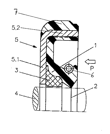
The invention will now be described in greater detail by way
of example only and with reference to the partial radial cross
section through an exemplary embodiment of a radial shaft seal
in accordance with the invention shown in the attached
drawlng .
The preferred radial shaft seal includes a sealing ring 1 made
of polymeric seal material, for example, rubber, and has a
sealing lip 2 which is supported on the shaft 4 to be sealed
by way of a backing ring 3 positioned on the non-pressurized
side of the sealing lip. The sealing ring 1 is permanently
affixed to a stiffening ring 5 made of deep drawn sheet steel.
The stiffening ring 5 has an angled profile with a radially

2180967
inwardly protruding leg 5.1 which partly overlaps and directly
contacts the backing ring 3.
The backing ring 3 is preferably made of hard plastic, for
example, polyamide, PTFE or bakelite. It is dimensioned so
that during the intended use, it surrounds the shaft 4 to be
sealed with slight clearance. The clearance is selected
sufficiently small so that even when pressures of up to 200
bar are applied in direction of the arrow shown in the
drawing, the seal material of the sealing ring is not forced
into the annular gap between the backing ring 3 and the shaft
4 need not be feared. The backing ring 3 prior to forming and
volcanization of the sealing ring 1 has been provided with a
surface coating of adherant oil, to prevent adhesion of the
sealing ring material during volcanization thereof.
Consequently, the backing ring 3 has an improved relative
movability with respect to the sealing ring. This is
sufficient to provide the sealing lip with the guidance
required to remain in continuous contact with the shaft 4
during radial displacements of the shaft. The sealing lip 2
is forced against the surface of the shaft 4 to be sealed by
way of circular coil spring 6 such as a garter spring. The
spring 6 is made of steel.
The seal in accordance with the invention preferably further
includes an outer seal ring 7 which is preferably made of
elastomeric material vulcanized onto the radially outwardly
directed surface of the axially extending portion 5.2 of the
stiffening ring 5. The outer seal ring 7 ensures proper
seating and sealing of the seal in the seal receiving opening
(not shown). Preferably the outer seal ring 7 is made of the
same material as the sealing ring 1 and manufactured
concurrently therewith. This is most efficiently achieved by
providing at least one radial passage (not shown) through the
axial portion 5.2 of the stiffening ring 5 which allows cross-
flow of the seal raw material when the free space of the tool
cavity is filled with the seal raw material during manufacture

2180967
of the seal. However, the outer seal ring 7 may also be
completely separate from the sealing ring 1 and made of a
different, preferably less costly material for economic
reasons. In that case, the raw materials of the outer seal
ring 7 and the sealing ring 1 are preferably simultaneously
vulcanized.
The radial shaft seal in accordance with the invention can be
especially easily manufactured and with high dimensional
stability. It is further distinguished by especially good use
characteristics at pressures up to 200 bar.
Changes and modifications in the specifically described
embodiments can be carried out without departing from the
scope of the invention which is intended to be limited only by
the scope of the appended claims.

Representative Drawing
A single figure which represents the drawing illustrating the invention.
Administrative Status

2024-08-01:As part of the Next Generation Patents (NGP) transition, the Canadian Patents Database (CPD) now contains a more detailed Event History, which replicates the Event Log of our new back-office solution.

Please note that "Inactive:" events refers to events no longer in use in our new back-office solution.

For a clearer understanding of the status of the application/patent presented on this page, the site Disclaimer , as well as the definitions for Patent , Event History , Maintenance Fee  and Payment History  should be consulted.

Event History

Description Date
Inactive: IPC expired 2016-01-01
Application Not Reinstated by Deadline 2002-03-25
Inactive: Dead - No reply to s.30(2) Rules requisition 2002-03-25
Deemed Abandoned - Failure to Respond to Maintenance Fee Notice 2001-07-10
Inactive: Abandoned - No reply to s.30(2) Rules requisition 2001-03-26
Inactive: S.30(2) Rules - Examiner requisition 2000-09-25
Amendment Received - Voluntary Amendment 1997-09-11
Inactive: Status info is complete as of Log entry date 1997-07-30
Inactive: Application prosecuted on TS as of Log entry date 1997-07-30
Amendment Received - Voluntary Amendment 1997-07-29
Application Published (Open to Public Inspection) 1997-01-11
All Requirements for Examination Determined Compliant 1996-11-04
Request for Examination Requirements Determined Compliant 1996-11-04

Abandonment History

Abandonment Date Reason Reinstatement Date
2001-07-10

Maintenance Fee

The last payment was received on 2000-06-13

Note : If the full payment has not been received on or before the date indicated, a further fee may be required which may be one of the following

  • the reinstatement fee;
  • the late payment fee; or
  • additional fee to reverse deemed expiry.

Patent fees are adjusted on the 1st of January every year. The amounts above are the current amounts if received by December 31 of the current year.
Please refer to the CIPO Patent Fees web page to see all current fee amounts.

Fee History

Fee Type Anniversary Year Due Date Paid Date
Request for examination - standard 1996-11-04
MF (application, 2nd anniv.) - standard 02 1998-07-10 1998-06-23
MF (application, 3rd anniv.) - standard 03 1999-07-12 1999-06-18
MF (application, 4th anniv.) - standard 04 2000-07-10 2000-06-13
Owners on Record

Note: Records showing the ownership history in alphabetical order.

Current Owners on Record
CARL FREUDENBERG
Past Owners on Record
HANS REINHARDT
ROLF VOGT
Past Owners that do not appear in the "Owners on Record" listing will appear in other documentation within the application.
Documents

To view selected files, please enter reCAPTCHA code :


To view images, click a link in the Document Description column (Temporarily unavailable). To download the documents, select one or more checkboxes in the first column and then click the "Download Selected in PDF format (Zip Archive)" or the "Download Selected as Single PDF" button.

List of published and non-published patent-specific documents on the CPD .

If you have any difficulty accessing content, you can call the Client Service Centre at 1-866-997-1936 or send them an e-mail at CIPO Client Service Centre.

({010=All Documents, 020=As Filed, 030=As Open to Public Inspection, 040=At Issuance, 050=Examination, 060=Incoming Correspondence, 070=Miscellaneous, 080=Outgoing Correspondence, 090=Payment})


Document
Description 
Date
(yyyy-mm-dd) 
Number of pages   Size of Image (KB) 
Abstract 1996-10-27 1 25
Description 1996-10-27 5 213
Claims 1996-10-27 1 43
Drawings 1996-10-27 1 13
Representative drawing 1998-03-24 1 12
Reminder of maintenance fee due 1998-03-10 1 111
Courtesy - Abandonment Letter (Maintenance Fee) 2001-08-06 1 182
Courtesy - Abandonment Letter (R30(2)) 2001-06-03 1 171
Prosecution correspondence 1996-11-03 3 111