Sélection de la langue

Search

Sommaire du brevet 2180967 

Énoncé de désistement de responsabilité concernant l'information provenant de tiers

Une partie des informations de ce site Web a été fournie par des sources externes. Le gouvernement du Canada n'assume aucune responsabilité concernant la précision, l'actualité ou la fiabilité des informations fournies par les sources externes. Les utilisateurs qui désirent employer cette information devraient consulter directement la source des informations. Le contenu fourni par les sources externes n'est pas assujetti aux exigences sur les langues officielles, la protection des renseignements personnels et l'accessibilité.

Disponibilité de l'Abrégé et des Revendications

L'apparition de différences dans le texte et l'image des Revendications et de l'Abrégé dépend du moment auquel le document est publié. Les textes des Revendications et de l'Abrégé sont affichés :

  • lorsque la demande peut être examinée par le public;
  • lorsque le brevet est émis (délivrance).
(12) Demande de brevet: (11) CA 2180967
(54) Titre français: GARNITURE D'ETANCHEITE RADIALE POUR ARBRE ET PROCEDE DE FABRICATION
(54) Titre anglais: REDIAL SHAFT SEAL AND PROCESS FOR ITS MANUFACTURE
Statut: Réputée abandonnée et au-delà du délai pour le rétablissement - en attente de la réponse à l’avis de communication rejetée
Données bibliographiques
(51) Classification internationale des brevets (CIB):
  • F16J 15/54 (2006.01)
(72) Inventeurs :
  • REINHARDT, HANS (Allemagne)
  • VOGT, ROLF (Allemagne)
(73) Titulaires :
  • CARL FREUDENBERG
(71) Demandeurs :
  • CARL FREUDENBERG (Allemagne)
(74) Agent: BORDEN LADNER GERVAIS LLP
(74) Co-agent:
(45) Délivré:
(22) Date de dépôt: 1996-07-10
(41) Mise à la disponibilité du public: 1997-01-11
Requête d'examen: 1996-11-04
Licence disponible: S.O.
Cédé au domaine public: S.O.
(25) Langue des documents déposés: Anglais

Traité de coopération en matière de brevets (PCT): Non

(30) Données de priorité de la demande:
Numéro de la demande Pays / territoire Date
P 19525054.0 (Allemagne) 1995-07-10

Abrégés

Abrégé anglais


A radial shaft seal is disclosed having a sealing ring of
polymeric material with at least one sealing lip supported on
the shaft to be sealed by a backing ring positioned on the
non-pressurized side of the sealing lip. The sealing ring is
permanently adhered to a stiffening ring having an angled
profile with a radially inwardly protruding leg that at least
partly overlaps and directly contacts the backing ring. A
process for the manufacture of such a radial shaft seal is
also disclosed wherein the stiffening ring and the backing
ring are together positioned in a tool cavity and the
remaining free space of the tool cavity is filled with a
liquid or pasty sealing material which is subsequently
solidified and adhered to the sealing ring to produce a
finished shaft seal. This provides a more economical process
of manufacture than prior art shaft seals and results in a
radial shaft seal of improved use characteristics.

Revendications

Note : Les revendications sont présentées dans la langue officielle dans laquelle elles ont été soumises.


THE EMBODIMENTS OF THE INVENTION IN WHICH AN EXCLUSIVE
PROPERTY OR PRIVILEGE IS CLAIMED ARE DEFINED AS FOLLOWS:
1. A radially shaft seal, comprising a sealing ring made
of polymeric seal material and having at least one radial
sealing lip, a stiffening ring and a backing ring located on
the non-pressurized side of the sealing lip, the sealing ring
being permanently affixed to the stiffening ring and the
sealing lip being supported on a shaft to be sealed by way of
the backing ring, and the stiffening ring having an angled
profile with a radially inwardly protruding leg which at least
partly overlaps and directly contacts the backing ring.
2. Process for the manufacture of a radial shaft seal
according to claim 1, comprising the steps of placing the
stiffening ring together with the backing ring in a tool
cavity in the mutual spacial arrangement required for the
intended use, filling the remaining free space of the tool
cavity with a liquid or pasty polymeric seal raw material,
solidifying the seal raw material, and adhering the seal
material to the stiffening ring, and removing the finished
radial shaft seal from the tool cavity.
3. Process according to claim 2, wherein the backing
ring prior to placement thereof into the tool cavity is
provided with a means for preventing adhesion of the polymeric
seal material.
4. Process according to claim 3, wherein the means for
preventing adhesion is admixed with the polymeric material
used for manufacture of the backing ring.
5. Process according to claim 3, wherein the means for
preventing adhesion is applied to the surface of a previously
manufactured backing ring.
6. Process according to claim 5, wherein the means for
preventing adhesion is an adherant oil.

Description

Note : Les descriptions sont présentées dans la langue officielle dans laquelle elles ont été soumises.

2180967
RADIAL SHAFT SEAL AND PROCESS FOR ITS MANUFACTURE
The invention relates to radial shaft seals. More
particularly, the invention relates to radial shaft seals
including a sealing ring made of polymeric sealing material
which is permanently affixed to a stiffening ring and has at
least one sealing lip. The invention also relates to a
process for manufacture of such a radial shaft seal.
A conventional seal of this general type is known from German
published Patent Application DE-OS 43 17 489. However, that
prior seal is expensive to manufacture and has unsatisfactory
use characteristics.
It is now an object of the invention to provide an improved
radial shaft seal of the above-described general type which
can be manufactured more economical and has improved operating
and use characteristics.
This object is achieved in accordance with the invention with
a radial seal wherein the stiffening ring has an angled
profile with a radially inwardly protruding leg which at least
partly overlaps and directly contacts a backing ring that is
located on the non-pressurized side of the sealing lip. The
backing ring supports the sealing lip in relation to the shaft
to be sealed.
Accordingly, the invention provides a radial shaft seal having
a sealing ring of polymeric seal material, for example,
rubber, which is permanently affixed to a stiffening ring and
has at least one sealing lip that is supported on the shaft to
be sealed by way of a backing ring located on the non-
pressurized side of the sealing lip. The stiffening ring has
an angled profile with a radially inwardly protruding leg
which at least partly overlaps and directly contacts the
backing ring. The backing ring is supported in axial
direction by the stiffening ring, which prevents axial evading
movements at high pressures and thus, ensures an excellent
guiding of the sealing lip. The radial shaft seal in

2180967
accordance with the invention can thereby be used without
problems for shaft diameters of up to 80 mm and at pressures
of the medium to be sealed of up to 200 bar. The opening
which receives the seal during use in accordance with the
invention can be shaped in a conventional manner as for
conventional radial shaft seals. Nevertheless, an excellent
guiding and support of the sealing ring and the backing ring
directly by portions of the stiffening ring is achieved, which
guiding is controlled during the manufacture of the radial
shaft seal. Manufacturing tolerances of the seal receiving
opening which are mostly controlled by the user of the seal
have substantially no influence on the function of the seal.
In the process used for the manufacture of the conventional
seal according to DE-OS 43 17 489, the stiffening ring is
placed in the tool cavity and the remaining space filled for
the forming of a sealing ring with a liquid or pasty seal raw
material. The seal raw material is thereafter solidified and
adhered to the stiffening ring and the seal subsequently
removed from the tool cavity. A backing ring is in this known
process independently manufactured and subsequently, in a
separate process step, inserted into a groove specifically
provided therefor in the sealing ring. This manner of
manufacture is complicated and expensive.
It is therefor a further object of the invention to provide a
radial shaft seal of significantly simplified manufacture
This further ob~ect is achieved in accordance with the
invention in a process wherein the stiffening and backing
rings are placed in the tool cavity together, whereby the
backing ring is positioned on the radially inwardly protruding
leg of the stiffening ring, whereafter the remaining free
space of the tool for the forming of the sealing ring is
filled with the required, polymeric seal raw material. The
backing ring is placed on the radially inwardly protruding leg
of the stiffening ring. Manufacturing tolerances of the

2180967
-- 3
stiffening and backing rings are automatically compensated by
directly forming the sealing ring onto the stiffening and
backing rings which were previously already inserted into the
tool cavity and in the mutual positioning required for the
intended use so that radial shaft seals are achieved which are
distinguished by an optimum dimensional stability. This is of
substantial advantage with respect to the eventually achieved
use characteristics.
Further improved use characteristics can be achieved when the
backing ring prior to its insertion into the tool cavity is
provided with a means for preventing adhesion of the polymeric
seal material forming the sealing ring. When such a means is
used, the backing ring has an improved relative movability
during use with respect to the sealing ring.
The means for preventing adhesion can be a substance admixed
with the raw material used for the manufacture of the backing
ring, which has proven especially practical. However,
alternatively or additionally, it is also possible to apply
the auxiliary means if desired to the surface of a previously
made backing ring, for example, in a submerging or spray-on
process step.
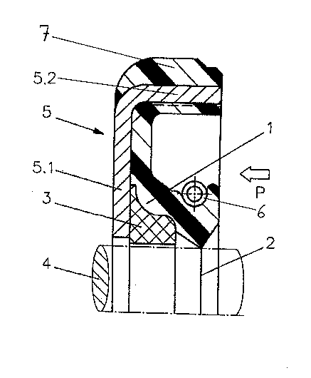
The invention will now be described in greater detail by way
of example only and with reference to the partial radial cross
section through an exemplary embodiment of a radial shaft seal
in accordance with the invention shown in the attached
drawlng .
The preferred radial shaft seal includes a sealing ring 1 made
of polymeric seal material, for example, rubber, and has a
sealing lip 2 which is supported on the shaft 4 to be sealed
by way of a backing ring 3 positioned on the non-pressurized
side of the sealing lip. The sealing ring 1 is permanently
affixed to a stiffening ring 5 made of deep drawn sheet steel.
The stiffening ring 5 has an angled profile with a radially

2180967
inwardly protruding leg 5.1 which partly overlaps and directly
contacts the backing ring 3.
The backing ring 3 is preferably made of hard plastic, for
example, polyamide, PTFE or bakelite. It is dimensioned so
that during the intended use, it surrounds the shaft 4 to be
sealed with slight clearance. The clearance is selected
sufficiently small so that even when pressures of up to 200
bar are applied in direction of the arrow shown in the
drawing, the seal material of the sealing ring is not forced
into the annular gap between the backing ring 3 and the shaft
4 need not be feared. The backing ring 3 prior to forming and
volcanization of the sealing ring 1 has been provided with a
surface coating of adherant oil, to prevent adhesion of the
sealing ring material during volcanization thereof.
Consequently, the backing ring 3 has an improved relative
movability with respect to the sealing ring. This is
sufficient to provide the sealing lip with the guidance
required to remain in continuous contact with the shaft 4
during radial displacements of the shaft. The sealing lip 2
is forced against the surface of the shaft 4 to be sealed by
way of circular coil spring 6 such as a garter spring. The
spring 6 is made of steel.
The seal in accordance with the invention preferably further
includes an outer seal ring 7 which is preferably made of
elastomeric material vulcanized onto the radially outwardly
directed surface of the axially extending portion 5.2 of the
stiffening ring 5. The outer seal ring 7 ensures proper
seating and sealing of the seal in the seal receiving opening
(not shown). Preferably the outer seal ring 7 is made of the
same material as the sealing ring 1 and manufactured
concurrently therewith. This is most efficiently achieved by
providing at least one radial passage (not shown) through the
axial portion 5.2 of the stiffening ring 5 which allows cross-
flow of the seal raw material when the free space of the tool
cavity is filled with the seal raw material during manufacture

2180967
of the seal. However, the outer seal ring 7 may also be
completely separate from the sealing ring 1 and made of a
different, preferably less costly material for economic
reasons. In that case, the raw materials of the outer seal
ring 7 and the sealing ring 1 are preferably simultaneously
vulcanized.
The radial shaft seal in accordance with the invention can be
especially easily manufactured and with high dimensional
stability. It is further distinguished by especially good use
characteristics at pressures up to 200 bar.
Changes and modifications in the specifically described
embodiments can be carried out without departing from the
scope of the invention which is intended to be limited only by
the scope of the appended claims.

Dessin représentatif
Une figure unique qui représente un dessin illustrant l'invention.
États administratifs

2024-08-01 : Dans le cadre de la transition vers les Brevets de nouvelle génération (BNG), la base de données sur les brevets canadiens (BDBC) contient désormais un Historique d'événement plus détaillé, qui reproduit le Journal des événements de notre nouvelle solution interne.

Veuillez noter que les événements débutant par « Inactive : » se réfèrent à des événements qui ne sont plus utilisés dans notre nouvelle solution interne.

Pour une meilleure compréhension de l'état de la demande ou brevet qui figure sur cette page, la rubrique Mise en garde , et les descriptions de Brevet , Historique d'événement , Taxes périodiques et Historique des paiements devraient être consultées.

Historique d'événement

Description Date
Inactive : CIB expirée 2016-01-01
Demande non rétablie avant l'échéance 2002-03-25
Inactive : Morte - Aucune rép. dem. par.30(2) Règles 2002-03-25
Réputée abandonnée - omission de répondre à un avis sur les taxes pour le maintien en état 2001-07-10
Inactive : Abandon. - Aucune rép dem par.30(2) Règles 2001-03-26
Inactive : Dem. de l'examinateur par.30(2) Règles 2000-09-25
Modification reçue - modification volontaire 1997-09-11
Inactive : Renseign. sur l'état - Complets dès date d'ent. journ. 1997-07-30
Inactive : Dem. traitée sur TS dès date d'ent. journal 1997-07-30
Modification reçue - modification volontaire 1997-07-29
Demande publiée (accessible au public) 1997-01-11
Toutes les exigences pour l'examen - jugée conforme 1996-11-04
Exigences pour une requête d'examen - jugée conforme 1996-11-04

Historique d'abandonnement

Date d'abandonnement Raison Date de rétablissement
2001-07-10

Taxes périodiques

Le dernier paiement a été reçu le 2000-06-13

Avis : Si le paiement en totalité n'a pas été reçu au plus tard à la date indiquée, une taxe supplémentaire peut être imposée, soit une des taxes suivantes :

  • taxe de rétablissement ;
  • taxe pour paiement en souffrance ; ou
  • taxe additionnelle pour le renversement d'une péremption réputée.

Les taxes sur les brevets sont ajustées au 1er janvier de chaque année. Les montants ci-dessus sont les montants actuels s'ils sont reçus au plus tard le 31 décembre de l'année en cours.
Veuillez vous référer à la page web des taxes sur les brevets de l'OPIC pour voir tous les montants actuels des taxes.

Historique des taxes

Type de taxes Anniversaire Échéance Date payée
Requête d'examen - générale 1996-11-04
TM (demande, 2e anniv.) - générale 02 1998-07-10 1998-06-23
TM (demande, 3e anniv.) - générale 03 1999-07-12 1999-06-18
TM (demande, 4e anniv.) - générale 04 2000-07-10 2000-06-13
Titulaires au dossier

Les titulaires actuels et antérieures au dossier sont affichés en ordre alphabétique.

Titulaires actuels au dossier
CARL FREUDENBERG
Titulaires antérieures au dossier
HANS REINHARDT
ROLF VOGT
Les propriétaires antérieurs qui ne figurent pas dans la liste des « Propriétaires au dossier » apparaîtront dans d'autres documents au dossier.
Documents

Pour visionner les fichiers sélectionnés, entrer le code reCAPTCHA :


Pour visualiser une image, cliquer sur un lien dans la colonne description du document (Temporairement non-disponible). Pour télécharger l'image (les images), cliquer l'une ou plusieurs cases à cocher dans la première colonne et ensuite cliquer sur le bouton "Télécharger sélection en format PDF (archive Zip)" ou le bouton "Télécharger sélection (en un fichier PDF fusionné)".

Liste des documents de brevet publiés et non publiés sur la BDBC .

Si vous avez des difficultés à accéder au contenu, veuillez communiquer avec le Centre de services à la clientèle au 1-866-997-1936, ou envoyer un courriel au Centre de service à la clientèle de l'OPIC.

({010=Tous les documents, 020=Au moment du dépôt, 030=Au moment de la mise à la disponibilité du public, 040=À la délivrance, 050=Examen, 060=Correspondance reçue, 070=Divers, 080=Correspondance envoyée, 090=Paiement})


Description du
Document 
Date
(aaaa-mm-jj) 
Nombre de pages   Taille de l'image (Ko) 
Abrégé 1996-10-27 1 25
Description 1996-10-27 5 213
Revendications 1996-10-27 1 43
Dessins 1996-10-27 1 13
Dessin représentatif 1998-03-24 1 12
Rappel de taxe de maintien due 1998-03-10 1 111
Courtoisie - Lettre d'abandon (taxe de maintien en état) 2001-08-06 1 182
Courtoisie - Lettre d'abandon (R30(2)) 2001-06-03 1 171
Correspondance de la poursuite 1996-11-03 3 111