Note: Descriptions are shown in the official language in which they were submitted.
WO 95/19638 ~ ~ ~ PCT/CA95/00014
title: ION SPRAY WITH INTERS$CTING FLOW
ZO FTRLD OF TSE INVENTION
This invention relates to method and apparatus for
forming ions from ~a liquid and for directing such ions
into a mass analyzer, typically a mass spectrometer.
BACKGROUND QF THE INVENTION
Electrospray interfaces are commonly used to receive
liquid from a liquid sample source such as a liquid
chromatograph ("LC") and to produce ions which are
delivered to a mass spectrometer. In electrospray, liquid
from the LC is directed through a free end of a capillary
tube, the tube being connected to one pole of a high
voltage source. The free end of the capillary tube is
spaced from an orifice plate having an orifice leading
(directly or through other equipment) into the mass
analyzer vacuum chamber. The orifice plate is connected
to the other pole of~ the high voltage source. The
electric field generates a spray of charged droplets,
producing liquid flow without a pump, and the droplets
evaporate to produce ions.
Because electrospray can handle only a very small flow
(larger flows produce larger droplets, causing the ion
signal to fall off and become unstable), a new technique
was developed, which can be referred to as nebulizer gas
spray. The nebulizer gas spray technique, shown in U.S.
patent 4,861,988 issued August 29, 1989 to Cornell
Research Foundation, involves providing a cocurrent flow
of high velocity nebulizer gas coaxial with the capillary
tube. The nebulizer gas nebulizes the liquid to produce
a mist of droplets which are charged by the applied
electrical field. While electrospray functions poorly at
liquid flows over about 10 microliters per minute,
nebulizer gas spray functions reasonably well at liquid
kl.\ . \ ()\' l~t'A \fl ~\l.ffL\ ~J!i y.,~. ~ ._ JV : __ wi~i ~ ~ r-t:~ c~;~
_~~;~.rt m..; m ~
2181040
_2_
flo~NS of up to between 100 and 200 microliters per minute. However even
with nebulizer gas spray, it is found that with liquid flows of the order of
about 100 microliters per minute, the sensitivity of the instrument is less
than at lower flows, and that the sensitivity reduces substantially at liquid
flows above 100 microliters per minute. It is believed that at least part of
the problem is that at higher liquid flows, larger droplets are produced and
do not evaporate to release ions before these droplets reach the orifice.
Therefore, much sample is lost.
Various attempts have been made to improve the sensitivity
lU of instruments using nebulizer gas spray and electrospray. For example, as
shown in U.S. patent 4,935,624 issued June 19, 1991J, attempts have been
made to heat the liquid before it is sprayed through the capillary tube.
However because heating the liquid in the capillary tube to a high
temperature will degrade thermally labile analytes, this method is not
desirable and has produced only a limited increase W sensitivity.
In another attempt to improve the results when using
electrospray, two researchers at the University of Alberta in Alberta,
Canada, namely Paul Kebarle and Michael Ikonomou, have recently
suggested surrounding an electrospray capillary with a cocurrent coaxial
sheath of heated entraining gas. The flow used is not a nebulizing flow,
but rather is a laminar flow of heating gas. It is found that this can
increase the sensitivity of the instrument by 3 to 5 times, but in practice
the
device has proven temperamental and the improvement is available only
within a very narrow range of operating parameters.
Various other attempts have been made to improve the
sensitivity of instruments using electrospray. For example, in U.S. patent
4,531,056 issued July 23, 1985, a gas {which may be heated) is introduced
into the electrospray chamber in a direction opposite to that of flow from
the electrospray capillary, to desolvate the sprayed droplets. A problem
with this arrangement is that the substantial flow used for the inert gas
tends to blow evaporating droplets away from the orifice into the vacuum
chamber.
AME~~(~Fn SNFFT
Rcv. vUV:EN~ vllt-W ctiEV uES et- 4-;~E; : _~_~. ~~ : -. Y~4;~ t3;~
vcsu:u4E_c;~:H~_~
2181040
-3-
Application W092/211~8 published November 2b, 1992
shows another arrangement for enhancing the dispersion of sample
solutions info small, highly charged droplets which can produce ions,
using mechanical vibration. This application discloses the use of a counter
current bath gas to desolvate ions, but since the flow is directly away from
the orifice through which the ions are to pass, again this arrangement may
reduce the ion signal.
U.S. patent 5,122,b70 issued June 16, 1992 shows an
electrospray source in which the liquid sample is sheathed with a sheath
liquid, and in which a drying gas again flows away from the orifice toward
the electrospray plume, thus enhancing the desolvation process but
tending to carry fine droplets away from the orifice.
Application W090/14148 published November 29, 1990 again
discloses an electrospray method in which a drying gas flows directly away
from the orifice and toward the electrospray plume, helping to desolvate
the droplets produced by the electrospray process but tending to carry these
droplets away from the orifice.
This invention in another aspect deals with controlled
denaturation of certain ions (e.g. protein ions). Denaturation of ions is
~~ell known, and it is well known that heating causes denaturation.
Denaturation of ions is discussed in a paper entitled "Stepwise Refolding
o~ Acid-Denatured Myoglobin: Evidence from Elecirospray Mass
Spectrometry" by R. Feng and Y. Konishi, published in the Journal of the
American Society for Mass Spectrometry, Vol. 4, No. 8, August, 1993, ISSN
1044-0305 pages 638-645. This article deals with denaturation and
unfolding using solution pH and explains how to eliminate unwanted
denaturation, for example by adjusting solution pH.
SUMMARY OF 7H1INVENTION
1t is therefore an object of the present invention to provide a
liquid analyte spray apparatus and method in which an intersecting flow
of heated gas is used to provide improved sensitivity. In one aspect the
AMERCED SHEET
CA 02181040 2004-02-26
-4-
invention provides a method of analyzing ions from trace sample molecules in
a liquid, comprising:
(a) providing a chamber having a capillary tube therein, said
capillary tube having a free end, said chamber having an
orifice member spaced from said free end and having an
orifice therein,
(b) directing said liquid through said capillary tube and out
said free end,
(c) generating an electric field in said chamber between said
free end and said orifice member,
(d) producing from said free end a first flow of charged
droplets of said liquid, and directing said first flow in a first
direction,
(e) producing a second flow of gas, heating said second
flow, and causing said second flow to contact said first
flow,
(f) drawing ions produced from said droplets through said
orifice into an analyzer located outside said chamber
beyond said orifice member,
characterized in that
(g) said second flow is directed in a second direction
different from said first direction, with each of said first
and second flows having a component of velocity
directed towards said orifice, for said second flow to
intersect said first flow at a selected region for turbulent
mixing of said first and second flows in said region,
(h) the heated gas from said second flow acting to push
droplets in said first flow towards said orifice and to assist
evaporation of droplets in said first flow to release ions
therefrom, as compared with the evaporation which
would occur in the absence of said heated gas from said
second flow.
CA 02181040 2004-02-26
-4a-
In another aspect the invention provides apparatus for analyzing
ions from trace sample molecules in a liquid comprising:
(a) a chamber,
(b) a capillary tube to receive said liquid and having a first
free end in said chamber for discharging said liquid into
said chamber,
(c) an orifice member in said chamber having an orifice
therein and being spaced from said free end, said orifice
defining an outlet from said chamber,
(d) means for creating an electric field between said free end
and said orifice member,
(e) means for producing from said free end a first flow of
charged droplets of said liquid, and for directing said first
flow in a first direction,
(f) means for producing a second flow of gas in said
chamber, and means for heating said second flow, and
means for causing said second flow to contact said first
flow,
(g) means for drawing ions produced from said droplets
through said orifice into an analyzer located outside said
chamber beyond said orifice member,
CA 02181040 2004-02-26
-4b-
characterized in that
(h) there are means for directing said second flow in a
second direction different from said first direction with
both said first and second flows having a component of
velocity directed toward said orifice, for said second flow
to intersect said first flow at a selected region for
turbulent mixing of said first and second flows at said
region,
(i) the heated gas from said second flow acting to push
droplets in said first flow towards said orifice and to assist
evaporation of droplets in said first flow to release ions
therefrom, as compared with the release of ions which
would occur in the absence of said heated gas from said
second flow.
In another aspect the invention provides a method of analyzing
ions from trace sample molecules in a liquid, said molecules being folded
molecules, said method comprising spraying said liquid from an opening to
form a plume of electrically charged droplets, each droplet containing said
ions, providing a flow of gas, causing said flow to mix with said plume to aid
evaporation of said droplets and emission of ions therefrom, characterized in
that said gas is heated to a controlled temperature to cause controlled
unfolding of said molecules in said droplets during evaporation of said
droplets, and then drawing ions emitted from said droplets out of the heated
gas and into a vacuum chamber, and analyzing said ions.
pCT/CA95I00014
WO 95/19638
- 5 -
of gas;
Fig. 3A, 38, and 3C are graphs showing variation
of sensitivity with intersecting gas flow and temperature
for liquid flows of 1 milliliter per minute, 200
microliters per minute, and 50 microliters per minute
respectively;
Figs. 4A, .48 and 4C are chromatograms for liquid
flow of 1 milliliter per minute;
Figs. 5A, 58, and 5C are chromatograms for
liquid flows of 200 microliters per minute;
Figs. 6A, 68, and 6C are chromatograms for
liquid flows of 50 microliters per minute;
Figs. 7A, 7B, and 7C are chromatograms~for
liquid flows of 200 microliters per minute;
Figs. 8A and 8B are chromatograms for liquid
flows of 2000 microliters per minute;
Figs. 9A to 9F inclusive are graphs showing mass
spectra at liquid flows of 5 microliters per minute;
Fig. 10 is a diagrammatic view showing a
modification of the Fig. 2 apparatus;
Fig. 11 is a diagrammatic view showing another
modification of the Fig. 2 apparatus;
Fig. 12 is a diagrammatic view showing another
modification of the Fig. 2 apparatus;
Fig. 13 is a diagrammatic view showing another
modification of the Fig. 2 apparatus; and
Fig. 14 is a sectional view along an axis of the
Fig. 13 apparatus.
Reference is first made to Fig. 1 which shows
diagrammatically a prior art nebulizer gas spray analyzer
10 generally as shown in U.S, patent 4,861,988. The
analyzer 10 includes an atmospheric pressure ionization
chamber 12, a gas curtain chamber 14, and a vacuum chamber
16. The ionization chamber 12 is separated from the gas
curtain chamber 14 by an orifice plate 18 containing an
wo 9sn9s3s 2 l 810 4 0 p~y~~s~oooi4
-s-
inlet orifice 20. The gas curtain chamber 14 is separated
from the vacuum chamber 16 by an outlet plate 22
containing an orifice 24.
The vacuum chamber 16, which is evacuated
through outlet 26 by pump 28, contains a commercially
available mass analyzer 30 (typically a tandem triple
quadrupole mass spectrometer). Ions from ionization
chamber 12 and drawn through orifices 20, 24 are focused
by ion lens elements 32 into analyzer 30. A detector 34
at the end of the analyzer 30 detects ions which pass
through the analyzer and supplies a signal at terminal 36
indicative of the number of ions per second which are
detected.
The liquid sample to be analyzed is typically
supplied from a liquid chromatograph 38 through capillary
tube 40 into chamber 12. The flow rate of the liquid
through capillary tube 40 is determined by the LC pump 42.
The portion of capillary tube 40 which enters chamber 12
is made of a conductive material and has one pole
(depending on the polarity of the ions desired) of a
voltage source 44 connected to it. The other pole of
source 44, and plate 18, are grounded. A source 46 of
pressurized gas (e.g. nitrogen) supplies a sheath tube 48
coaxial with and encircling capillary 40 with a high
velocity nebulizing gas flow which nebulizes fluid ejected
from capillary 40. The mist of droplets 50 formed is
carried toward the orifice 20 by the nebulizing flow. The
droplets 50 are charged by the voltage applied to
capillary 40, and as the droplets evaporate, ions are
released from them and are drawn toward and through the
orifices 20, 24.
As is conventional, the axis 52 of capillary 40
is aimed slightly off axis, i.e. slightly below the
orifice 20. Thus, large droplets which do not fully
evaporate by the time they reach orifice 20 simply impact
against the plate 18 and run down the plate where they are
collected (by means not shown). Ions released from the
rcric~sroooi4
J"' WO 9S/19638
fine droplets which have evaporated are drawn through the
orifices~20, 24 into the vacuum chamber 16, where they are
focused into the analyser 30. As is well known, a curtain
gas (typically nitrogen) from curtain gas source 54
diffuses gently out through orifice 20 to prevent
contaminants in chamber 12 from entering the vacuum
chamber 16. Excess gas leaves chamber 12 via outlet 56.
As mentioned, a difficulty with the apparatus
shown in i~ig. 1 is that as the liquid flow rate is
increased, the sensitivity of the instrument does not
increase groportionately. It is believed that this is
because much of the increased sample flow is lost in
coarser droplets which do not have time to evaporate by
the time they reach interface plate 18. Increasing the
velocity of the nebulizing gas flow through sheath tuba 48
provides only very limited improvement.
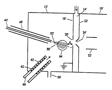
Reference is next made to Fig. 2, which shows a
portion of the Fig. 1 apparatus fitted with an improvement
according to the invention. In Fig. 2 primed reference
numerals indicate parts corresponding to those of Fig. 1.
The diffmrence between the Fig. 1 and Fig. 2
apparatus is that in Fig. 2, a.flow of intersecting heated
gas (typically nitrogen but clean dry air can be used) is
provided via tube 60. The diameter of tube 60 may vary,
but in one embodiment the internal diameter of tube 60 was
6.0 mm. The area of the tube 60 (28.3 mm2) was much larger
than the area of the annulus between nebulizing gas tube
48' and capillary tube 40' . (The inner diameter of tube 48'
was 0.432 mm, and the outer diameter of capillary tube 40'
was 0.4 mm, so the area of the annulus between them was
only 0. 021 mm2. )
The flow. of gas through tube 60 is relatively
high. For example, while the flow of nebulizing gas
through tube 48' is typically one liter par minute, the
flow of gas through tube 60 may be of the order of 1 to 10
liters per minute. The gas in tube 60 is heated by
heating coil 62 which encircles tube 60. Insulation 63
218 i 0 4 0 pCTlCA95/00014
R'O 95/19638
_ g
encircles heater coil 62 and the downstream part of tube
60 which is not encircled by the heater coil, to minimize
heat loss from the gas before it leaves the tube 60.
The velocity of the nebulizing gas from tube 48'
is normally very high, typically about 100 to 1,000 meters
per second (the sonic limit) and a flow rate in the range
0.25 to 2 liters per minute as it leaves tube 48'. Of
course this velocity is reduced downstream of the free end
of tube 48' due to mixing with the surrounding gas and with
the liquid. The velocity of the gas from tube 60 is much
lower and varies ( depending on f low ) from about 0 . 2 5 to 10
meters per second and a flow rate in the range 0.25 to 10
liters per minute.
The flow of gas from tube 60 is preferably aimed
to intersect the flow of gas and droplets from tubes 40',
48' at region 64, outlined by a circle. The downstream
edge of region 64 is spaced slightly in front of the
orifice 20'. Preferably such spacing, indicated by
dimension d, is about 1 centimeter. It is found that
spacing the intersection region 64 upstream of orifice 20'
helps reduce the likelihood of large droplets entering the
orifice 20~ and therefore reduces chemical noise in the
signal detected at detector 34.
The flow of heated gas from tube 60, as it
intersects the flow of gas and droplets from tubes 40',
48', produces turbulent mixing in front of the orifice 20' .
The turbulent mixing with heated gas serves to rapidly
evaporate the droplets 50' , thus increasing ion emission
and reducing sample wastage. Without the turbulent mixing
from the heated cross flow of gas, large droplets are
observed to impinge on plate 18' before ion emission can
occur, resulting in considerable sample wastage. With the
heated cross flow all or most of the population of
droplets is reduced to sufficiently small dimensions (< 1
micron for each droplet) for ion emission to occur. In
addition, the force of the jet of gas from tube 60 has a
focusing effect, pushing the mist of fine droplets 50'
2181040
~~°° WO 95/19638 PCT/CA95~0014
- g _
toward the orifice 20' so that ion emission can occur in a
region immediately in front of the orifice and a greater
flux of ions can then pass through the orifice into the
ion focusing element 32'. As will be seen, both the
heating and focusing effects are useful, and they appear
to function together to produce very substantial
improvements in sensitivity.
While the method and apparatus shown in
connection with Fig. 2 improves sensitivity over a wide
range of liquid flow rates, it is found that the
sensitivity incrrtases are greater at high liquid flow
rates. For purposes of this description, it is noted that
liquid flow rates from an LC may be classified as follows:
1. 1 to 25 microliters per minute - low flow
2. 25 to 75 microliters per minute - low to
intermediate flow
3. 75 to 300 microliters per minute - high
inter~diate f low
4. 300 to 2,000 microliters per minute (and
above) - high flow
Reference is next made to Figs. 3A to 3C, Which
show sensitivity improvements achieved at high, high
intermediate and lots intermediate liquid flow rates
respectively, utilizing the device shown in Fig. 2.
Specifically, Figs. 3A to 3C are graphs showing
on the horizontal axis gas flow through tube 60 in liters
per minute. On the vertical axis the relative signal
increase for the compound being analyzed is displayed. To
obtain this value the signal in ion counts per second
(cps), at any experimental point in the curve, is
normalized to the signal obtained when no intersecting gas
flow from tube 60 is used. Thus the first value (at air
flow = 0) for relative signal increase on all curves in
Figs . 3A to 3C is 1. In each graph of Figs . 3A to 3C,
three curves are shown for heater temperatures of 300°C,
400°C, 500°C and respectively. It is noted that these
temperatures were measured at the wall of tube 60 directly
WO 95/19638 ~ ~ ~ ~ PCT/CA95100014
- 10 -
beneath the heater coils 62 and that the temperature of
the gas leaving tube 60 would be substantially lower, and
would be between about 40% and 50% of the heater
temperature.
The compound used to produce the graphs of Figs.
3A to 3C was omeprazole, dissolved in a solution which was
about 65% water. For each of Figs. 3A, 3B, and 3C, 50, 5,
and 0.25 picograms of omeprazole respectively were
injected onto a commercially available high pressure
liquid chromatograph column (FiPLC) of 10 cm length. The
omeprazole then eluted from the column and passed into
chamber 12 to produce each measured point on the curves.
The signal is obtained by filtering the parent molecular
ion at m/z 346 through the first mass analyzer of a triple
quadrupole mass spectrometer, and then after fragmentation
in the collision cell region, measuring the signal
obtained on the most intense daughter ion at m/z 198 of
omeprazole. For Fig. 3A the column internal diameter was
4.6 mm thus accommodating a liquid flow of 1 milliliter
per minute. For Fig. 3B the column internal diameter was
2.lmm, thus accommodating a liquid flow of 200 microliters
per minute. For Fig. 3C the column internal diameter was
Z mm, thus accommodating a liquid flow of 50 microliters
per minute.
In Fig. 3A, where the liquid flow rate was 1
milliliter per minute (high flow rate), curves 72, 76, 78
were produced at heater temperatures of 300°C, 400°C and
500°C respectively. As mentioned, with no gas flow through
tube 60, the relative signal increase is 1, i.e. no signal
increase. The signal increased approximately 5 times at
a gas flow of 4 liters per minute with the heater at 300°C
(curve 72), and increased by 50 times at the same gas flow
rate when the heater was 500°C (curve 78j . As the gas flow
rate then increased to 7 liters per minute, the relative
signal increase rose to 100 times at a heater temperature
of 500°C ( curve 78 ) . The sensitivity increase was somewhat
less but still substantial at lower heater temperatures,
218 i 0 4 p~,~,~~~4
wo ~~~s
- 11 -
as shown.
It is believed that some of the reasons why
there was limited sensitivity increase up to 4.0 liters
per minute gas flow through tube 60 in Fig. 3A, were that
at~ lower gas flow rates the focusing effect of the
intersecting flow was less pronounced, and also the total
quantity of heat~added to the intersection region 64 was
reduced since less heated gas was delivered to this
region.
Refer~~ce is next made to Fig. 38, which shows
curves 78, 80, 82 similar to those of Fig. 3A but with a
liquid flow rate of 200 microliters per minute (high
intermediate flow) , and using heater temperatures of 300°C,
400°C and 500°C respectively.
With no gas flow through tube 60, the relative
signal increase in Fig. 3H is 1, i.e. no signal increaae.
At a gas flow rate from tube 60 of 7 liters per minute,
with the heater 62 at 500°C (curve 82), the ion signal was
increased by more than 40 times.
R~ference is next made to Fig. 3C, which shows
ion signals achieved at a liquid flow rate of 50
microliters per minute (low to intermediate flow). Curves
84, 86, 88 represent ion signals achieved at various gas
flow rates from tube 60 at heater temperatures of 300°C,
400°C and 500°C respectively.
In Fig. 3C it will be seen that, without any gas
flowing through tube 60, the relative signal increase is
l, i.e. no signal increase. With a gas flow through tube
60 of about 7 liters per minute and at the highest
temperature used ( 500°C for the heater 62 ) , the relative
signal increase is approximately 8 timea (curve 88).
Since the problem of a decrease in sensitivity
for nebulizer gas spray occurs primarily at higher liquid
flows, and since it is usually desired to operate
instruments at higher flows for greater throughput, the
very large increases in sensitivity at high liguid flows
are well matched to practical needs.
wo 9s~m3s 2 ~ 8 ~ ~ 4 0 rc~rica~sioooia
- 12 -
Reference is next made to Figs. 4A to 4C
inclusive, which show ion current chromatograms for
omeprazole injected onto a 4 . 6 mm I . D . HPLC column at 1
milliliter per minute (high flow) then eluting into
chamber 12' through capillary 40' after approximately 0.75
minutes. The mobile phase was composed of approximately
65% water. In the example shown in Figs. 4A and 4B 50
picograms of analyte was injected. In the example shown
in Figs. 4C, 0.5 picograms (500 femtograms) was injected.
In Figs. 4A to 4C, the vertical scale is
normalized and is indicated as relative intensity, with
the highest peak representing 100%. The number of counts
per second represented by the peak is shown in the upper
right hand corner of each drawing. The signal is obtained
by filtering the parent molecular ion at m/z 346 through
the first mass analyzer of a triple quadrupole mass
spectrometer, and then after fragmentation in the
collision cell region, measuring the signal obtained on
the most intense daughter ion at m/z 198 of omeprazole.
Time in minutes is plotted on the horizontal scale.
In Fig. 4A, where 50 picograms of omeprazole
were injected, with no gas flow through tube 60, it will
be seen that the peak 90 representing omeprazole was 70
cps, and that there was a significant amount of background
noise, represented at 92. Since it is generally
considered that the limit of reliable detection requires
the signal to be about twice the level of the background
noise, the system and method represented by Fig. 4A were
near the limit of detection with 50 picograms of analyte.
The chromatogram shown in Fig. 48 was made under
the same conditions as for Fig. 4A, with 50 picograms
injected, the only difference being that a flow of 7
liters per minute of heated gas was injected through tube
60, with the heater 62 operated at 500°C. It will be seen
that the omeprazole peak 94 was 6,423 cps, more than a
ninety-fold increase. The background noise 96 remained
nearly unchanged in absolute amplitude from that shown in
21810 4 p PCT/CA95I00014
WO 9511'63$
- 13 -
Fig. 4A and is th~refore virtually unnoticeable in Fig.
4B:
In Fig. 4C, as mentioned, the same liquid and
intersecting gas flow rates and gas temperature were used
as in Fig. 4B, but only 0.5 picograms of analyte were
injected, 100 fold less than in Figs. 4A and 4B. It will
be seen that the peak 98 representing omeprazole was now
80 cps, i.e. slightly more than that of Fig. 4A, although
only 1% of the ,pa~ount of sample was used. The background
noise 100 was slightly less for Fig. 4C than for Fig. 4A.
Thus, the sensitivity achieved in the Fig. 4C experiment
was more than 100 times greater than that achieved for
Fig. 4A.
Reference is next made to Figs. 5A to 5C
inclusive, which show ion current chromatograms for
omeprazole injected onto a 2.1 mm I.D. HPLC column at 200
microliter per minute (high intermediate flow) then
eluting into chamber 12' through capillary 40' after
approximately 1.6 minutes. The mobile phase was composed
of approximately 65% water. In the example shown in Figs.
SA and 5B 5 picograms of analyte was injected. In the
example shown in Figs. 5C 0.15 picograms (150 femtogrsms)
was injected.
In Fig 5A no gas was injected through tube 60.
The peak '102 repre~:enting omeprazole was 58 cps, with
significant background noise 104.
For Fig. 58 the same test procedure and
parameters as for Fig. 5A were used, except 7L/min. of
nitrogen at 500 was injected through tube 60. The peak
105 was 2465 cps, with no significant increase in
background noise 106. The sensitivity achieved in the
experiment shown in Fig. 5B was more than forty times that
achieved in Fig. 5A. In Fig. 5C the same experimental
conditions were used ras for Fig. 58 except 0.15 picograms
was injected. The cps for the peak 107 were 93, i.e.
slightly gr~ater than those for the peak 102 in Fig. 5A
even though 33 times less sample was injected.
X181040
WO 95/19638 PCTlCA95/00014
- 14 -
Reference is next made to Figs. 6A to 6C
inclusive, which show ion current chromatograms for
omeprazole injected onto a 1.0 mm I.D. HPLC column at 50
microliter per minute (low to intermediate flow) then
eluting into chamber 12' through capillary 40' after
approximately 1.8 minutes. The mobile phase was composed
of approximately 65$ water. In the example shown in Figs.
6A and 6B 250 femtograms of analyte was injected. In the
example shown in Figs. 6C 25 femtograms was injected.
In Fig. 6A no gas was injected through tube 60.
The peak 110 representing omeprazole was 103 cps and there
was significant background noise 112.
In Fig. 6B, 7 liters per minute of gas were
injected through tube 60 with the heater 60 at 500°C. The
same total analyte quantity was injected as in 6A (250
femtograms). The peak 113 representing omeprazole was 900
counts per second, with background noise 114 about the
same as in Fig. 6A. Thus, even at this relatively low
flow rate, the sensitivity was increased by about nine
times. In Fig. 6C the same experimental conditions were
used as for Fig. 68 except 25 picograms was injected. The
cps for the peak 117 were slightly greater than those for
the peak 110 in Fig. 6A even though 10 times less sample
was injected.
Reference is next made to Figs. 7A to 7C
inclusive, which show chromatograms for another compound,
ritodrine, injected through capillary 40' at a flow rate of
200 microliters per minute onto a 2.1 mm ID HPLC column
with the mobile phase solution containing about 35$ water.
In Fig. 7A 5 picograms of analyte was injected. No gas
was injected through tube 60. This produced peak 130 at
386 cps with low background noise 132.
Fig. 7B was made using the same method and
parameters as in Fig. 7A, except that 7 liters per minute
of heated gas, with the heater 62 adjusted to 400°C, was
injected though tube 60. This produced a peak 134 at
17,060 cps (a 44 times increase in sensitivity), with
WO 95/19638 ~ O ~ ~ PCT/CA95/00014
- 15 -
insignificant background noise 136.
Fig. 7C was made by injecting 150 femtograms of
ritodrine through capillary 40', again at 200 microliters
' per minute. The same heated gas flow rate and temperature
were used as in Fig. lOS. This produced peak 138 at 595
cps, with relativ~ly low background noise 140. The
sensitivity was nearly the same as in Fig. 7A even though
33 times 1~ss material was injected.
All the above graphs were produced using
positive ions. Figs. 8A and 88 show chromatograms
produced using negative ions. In Figs. 8A and 8B, 2
nanograms of taurochloric acid [0.4 pg/~L] was injected
onto a 4.6 mm ID HPLC column at a flow rate of 2
milliliters per minute (high flow rate) using a mobile
phase solution of 40% water. In Fig. 8A no gas was
injected through tube 60, while in Fig. 8H gas at 7 liters
per minute, with heater 62 at 500°C, was injected. This
produced a psrak 142 in Fig. 8A of 970 cps, and a peak 144
in Fig. 88 of 53,770 cps, a 55 times increase.
While Figs . 8A, 8B show injected liquid f lows of
2 milliliters per minute, higher f lows, a . g . 3 milliliters
per minute, may also be used with the invention, with a
resultant sensitivity increase.
Three unexpected effects obtained with the
present invention were: a) a large sensitivity increase as
described above, b) a general lack of thermal degradation
of labile compounds despite the substantial amount of
heat applied, and c) the ability to use the injected heat
to carefully regulate the degree to which a protein
molecule can be denatured. These three effects will be
further described below.
All three example compounds described above,
omeprazole, ritodrine, and taurocholic acid are materials
that normally degrade when exposed to temperatures in
excess of 100°C, yst signal from the intact molecular ion
increased rather than decreased when exposed to gases at
temperatures in great excess of this.
WO 95/19638 ~ ~ ~ ~ ~ pCT~CA95/00014
- 16 -
Protein molecules, which have very high
molecular weights and are even more labile than the above
mentioned compounds, were also tested. Reference is made
to Figs. 9A to 9F inclusive Which show the mass spectra of
the protein wheat germ agglutinin (molecular
weight=17,081) when taken with varying levels of heat and
gas flow through tube 60. On the horizontal axis is
plotted the mass-to-charge ratio of the ions being
generated. The total signal as measured in counts per
second is in the upper right hand corner of each spectrum.
The vertical axis is normalized intensity relative to the
most intense signal in the spectrum in Fig 9F. In each
case the sample, at a concentration of 1
milligram/milliliter, was dissolved in 100% water + 1%
formic acid and flowed through capillary 40' at a rate of
5~L/min (low flow). In Fig. 9A there is no gas flow
through tube 60. In Figs. 9B to 9F the gas flow is 7
liters per minute at heater temperatures of 100°C, 200°C,
300°C, 400°C, and 500°C respectively. Each peak in the
spectra represent a multiply charged molecular ion. The
number of charges on the ion associated with each peak is
indicated by a number above the peak followed by a + sign,
e.g. 8 positive charges for peak 121. The three effects
described above are observed, namely: increase in
sensitivity, freedom from thermal degradation, and protein
denaturation resulting in the unfolding of the protein
with increase in the number of charges observed on the
molecule.
It will be seen that as the heater temperature
62 increases, the number of counts per second for the
dominant peak increases from 72,222 in Fig. 9A to 795,556
in Fig. 9F (a ten fold increase in sensitivity at low
flows). Also, more intact molecular ions appear with
increasing charge state but no fragment ions from thermal
degradation are observed. At least five other minor
related proteins are also present in the sample (eg. peak
121 in Fig. 9A) and are observed as small satellite peaks
21810 4 0 rcricA9siooola
"'"" WO 95/19638
- 17 -
around the mayor charge state ions. These are not
fragments but rather different protein molecules present
in this impure pr~paration of wheat germ agglutinin.
It is believed that thermal degradation does not
occur for the following reason: The sample is transferred
to the ion source in a flowing stream of liquid contained
in a capillary transfer line. The liquid in the capillary
is itself not heated. Evan the tip of the nebulizer gas
spray devise remains cool as a result of the adiabatic
expansion of nebulizer gas. The heat is applied after the
sprayer by a separate heated gas stream emanating from
tube 60 which intersects the flow of liquid droplets.
When the heated gas from tube 60 is applied to the
droplets, the temperature of the droplets does not
increase to a point where thermal degradation would occur;
instead, the droplets begin to evaporate and cool at a
rate nearly matching the thermal input from the heated
gas. As the droplet dimensions become sub-micron,
individual sample ions, clustered with a protective shell
of a few soleent molecules, leave the droplet by the well
known ion evaporation process, before the droplet becomes
a solid residue. The ion-solvent cluster is rapidly drawn
by applied voltage potentials out of the hot gas and into
the cooler curtain gas where the final declustering of the
ion from the solvent molecules occurs as a result of
collisions with curtain gas molecules. The expansion into
the vacuum chamber 16' provides further cooling. The
residence time of the ion-solvent cluster species in the
hot gas is a few milliseconds or less which limits the
time for severe thermal degradative processes to occur.
By severe d~gradative processes we refer to the fracturing
of covalent chemical bonds in a molecule.
In Figs. 9A to 9F, as the temperature is
increased the number of charges on the molecular ions also
increases. This is a result ~of the dissociation of
hydrogen bonds and bonds held by Van Der Walls forces at
the slightly elevated temperatures the molecules
2181040
WO 95/19638 PCT/CA95/00014
- 18 -
experience inside the evaporating droplets, causing the
molecules (which are normally folded) to unfold. When the
molecule unfolds, basic residues previously buried within
the molecule, sequentially become exposed to solution
protons and attract an additional charge. With this
invention this process can be controlled and different
degrees of denaturation are accessible by varying the
temperature of gas from tube 60. This is illustrated in
Figs. 9A to 9F. With knowledge of the heat input one can
make calculations regarding the bonding energies and
stabilities of the different tertiary structures. The
study of the non-covalent interactions of proteins with
other molecules such as enzyme substrates, receptor
ligands, and antibody antigens can be advanced in this
way.
Although it is well known that heating causes
denaturation, it had always been believed that such
denaturation is a relatively slow process, taking between
tens of seconds and minutes to occur. With this invention
the denaturation effect is instantaneous. The moment the
gas temperature is changed, the spectra are altered. The
method and apparatus described will denature proteins more
than one thousand times faster than processes known to
occur in solution. This is an unexpected result. Since
the lifetime of the droplets is known to be only a few
milliseconds (e. g. less than 10 milliseconds), and since
the method heats only the highly charged droplets, it
follows that denaturation is occurring in a very short
time, on the order of between microseconds and
milliseconds. This capability would allow for very rapid
determinations on large numbers of different tertiary
conformations while consuming a very small amount of
sample.
Additionally the denaturation facilitates
analysis of many proteins by effectively extending the
mass range of the mass spectrometer. Proteins that
normally pick up only a few charges due to high degrees of
WO 95/19638 ~ r O q. ~ PCT/CA95/00014
- 19 -
folding could have a maximum mass charge ratio beyond the
mass range of the mass analyzer. With this method
described, more charges can be imgarted to a molecule thus
bringing the signal into the normal scanning range of the
mass analyzer.
This ~ffect was seen in Figs. 9A to 9F for wheat
germ agglutinin determined on a mass analyzer Whose
scanning limit was 2400 mass to charge units . The same
effect was observed for other tightly folded proteins.
Reference is made to Fig. 9A. In Fig. 9A, where there was
no gas flow through tube 60, a single dominant peak 120
was obtained, of intensity 72,222 cps. Because only a
single large peak was located and because the number of
charges associated with the peak was not known, it was not
possible reliably to determine the molecular weight of the
substance being analyzed.
However, as shown in Fig. 9F, when heat is
applied several consecutive charge states appear shown as
the four peaks or groups of peaks 122, 124, 126, 128.
With more than one charge state ion in the spectrum one
can calculate the number of charges on each ion and thus
obtain the molecular weight with the use of two
simultaneous equations. In this case 8 positive charges
were determined for peak 122, 9 for peak 124, 10 for peak
126 and il for peak 128. The mass to charge ratio for each
peak 122 to 128 is shown above the peaks. This allowed the
molecular weight of wheat germ agglutinin to be determined
as 17,081.
It is found that the precise angle at which tube
60 is aimed is not highly critical and that variations can
be made in this angle. However reference is made to Fig.
10, which shows at 52' the axis or trajectory of flow from
tubes 40', 48', and shows at 150 the axis or trajectory of
flow from tube 60. It will be seen that tra jectory 52' can
be resolved into a velocity component 52a which is
parallel to the axis 152 of flow through the orifice 20',
and a component 53b which is perpendicular to axis 152.
2181040
WO 95/19638 PCT/CA95/00014
- 20 -
Similarly, trajectory 150 can be resolved into a component
150a parallel to axis 152 and a component 150b
perpendicular to axis 152. It is desirable that the flow
of gas from tube 60 have some velocity component parallel
to the axis 152 in order to have a focusing effect, i.e.
in order to help push the droplets in the intersection
region 64 toward the orifice 20'. The right angle
component 150b, which is oppositely directed to the
component 52b of trajectory 52', helps push the fine
droplets upwardly (as illustrated) toward the orifice 20'
and thereby assists with the focusing effect, while at the
same time permitting the coarse droplets to continue on a
trajectory to impact the inlet plate 18' . The intersection
of oppositely directed components of the flows also
creates considerable turbulence, which helps to transfer
heat to the droplets 50' and to evaporate them rapidly.
Although the downstream edge of the intersection
region 64 is preferably close to but spaced upstream from
the orifice 20', e.g. by about 1 centimeter from the
orifice, nevertheless improved results are obtained even
if the intersection region of the flows borders on or is
in the orifice. However intersection bordering or in the
orifice 20' tends to force larger droplets through the
orifice, creating an increase in background chemical
noise, which is generally undesirable.
The upstream edge of the intersection region 64
preferably does not impinge on tube 40'. It was
discovered that it is not desirable to heat the liquid
stream directly in the capillary tube of the nebulizer
spray device by so directing the heated gas stream at the
sprayer tip or heating it by other means such as
electrical resistive heating. If tube 40' transferring
the liquid is heated directly or indirectly (by passing a
hot gas directly over tube 40') it is difficult to avoid
momentary overheating of the liquid which leads to boiling
and degassing of the liquid in the tube resulting in
instabilities in the spray and ion generation process,
~ ~ 8 I 0 4 0 ~,~~4
wo ~s,ms
- 21 -
tube plugging from solids deposition, sensitivity loss,
and thermal degradation of compounds. Applying the heat
after the liquid and sample leave tube 40' as a spray of
droplets represents a distinct advantage of the preferred
embodiments of this invention over one that directly heats
the liquid in the tube or heats the nebulizer gas
surrounding tube .40' and flowing within tube 48'. The
heat can now be selectively deposited in the region where
it is required, in the droplet plume 64, thereby avoiding
problems that arise when the bulk liquid in tube 40' is
heated. (Of course if tube 40' were adequately insulated
or cooled, then the hot gas could pass over that tube
without thermally degrading the sample.) The temperature
of the gas from tube 60 may be set within a wide range, as
desired. For example it may range between 100°C and 850°C.
Although Figs . 2 and 10 show that the flows from
the two sets of tubes shown all have a velocity component
directed toward orifice 20', such component can be achieved
in other ways. For example, and as shown in Fig. 11 where
double primed reference numerals indicate parts
corresponding to those of Figs. 1, 2 and 10, tubes 40",
48" and 60" may be coaxial and aimed at each other, with
their common axis 160 being at right angles to the axis
152" through orifice 20". In such case the velocity and
volume of the gas through tube 60" are typically made
about the same as those from tube 48", so when the two
flows intersect in region 64" (and allowing for the
momentum of the liquid flow), there is no net movement
along axis 160. In addition, since the diameter of tube
60" is now smaller because of the higher velocity gas flow
through it (its diameter is typically 6 mm), the
intersection region 64" is smaller than region 64,
providing increased concentration of ions. Movement of
droplets along axis 152" toward orifice 20" is provided by
a third flow of gas (e.g. N2) from another tube 162, the
axis of which extends through the intersection region 64"
and coincides with axis 152". The gas flow from tube 162
W0 95/19638 2181 Q 4 p p~~CA95/00014
- 22 -
is typically lower velocity than the gas flows through
tubes 48", 60" since its main purpose is to move droplets
toward orifice 20". If desired, the gas from tube 162 can
also be heated, by heater 164.
It is however preferred to use the arrangement
of Fig. 2, or a variation thereof, e.g. as shown in Fig.
12, where the careful balance of the three gas flows shown
in Fig. 11 is not required. The net velocity component
toward the orifice is provided by the angles of tubes 40'
and 60'. In Fig. 12 a slow broad laminar flow is provided
of clean gas 165 passing through orifices in tube 165a.
The flow of gas 165 is across a front much wider than that
of region 64 and may have a velocity of between 1 and 10
meters per second. This broad slow flow has the advantage
of entraining the ionization region 64 in a purified
atmosphere and prevents the secondary vortexes produced by
the turbulent mixing in region 64 from recirculating
contaminated air from the surrounding environment which
would lead to an increase in background chemical noise.
However if desired, the arrangement of Fig. I3
can be used, where triple primed reference numerals
indicate parts corresponding to those of the previous
figures. In Fig. 13 the tubes 48"', 60"' are aimed
directly at each other and at right angles to axis 152"',
but there is no third tube. In this case, if the momenta
of the flows from tubes 40"', 48"' and from tube 60"' are
balanced (i.e. made equal and opposite), the products of
the intersection of the flows will spread out in a thin
disc 166 in a plane of symmetry 168 (Fig. 14j. The plane
168 contains the axis 152"' through orifice 20"' and is at
right angles to the common axis 150"' of tubes 48"', 60"'.
In the Fig. 13 arrangement, the intersecting
flows do not produce net movement of droplets toward the
orifice, and in fact since droplets tend to move along
radii of disc 166, some tend to move away from the orifice
20"'. However since with sufficient heating the droplets
evaporate to produce ions in milliseconds, and since the
W095/19638 , 23 ~ ~ ~ ~ O ~ O PGT~CA95/00014
ions will then be drawn toward the orifice by the applied
electric field, reasonably good results can still be
obtained without a third jet. In addition, if the gas
curtain chamber 14 is removed and, as shown in Fig. 13,
the orifice 20"' leads directly into a vacuum chamber 16"',
the "inhaling" effect of the orifice will itself produce
an effect similar to that of the third jet, producing net
movement of droplets toward the orifice. However without
a gas curtain, the orifice 20"' is more likely to clog.
If also desired, the nebulizer gas flow in tube
48 can- be reduced to zero (and tube 48 eliminated), and
the apparatus can be operated simply as an electrospray
source. Any of the arrangements described and shown in
Figs. 2, 11, 12 or 13 may be operated in this manner. The
momentum of the respective flows will of course be
balanced (e. g. in the Figs. 11 or 13 arrangement) so that
there is no net movement up or down from plane 168. Even
at the low liquid flows associated with electrospray, the
invention provides a significant improvement in
sensitivity, at very low cost.
While preferred embodiments of the invention
have been described, it will be realized that changes may
be made within the scope of the appended claims.