Note: Descriptions are shown in the official language in which they were submitted.
2181285
DESCRIPTION
The invention concerns a bath lift for disabled persons, with
a base frame, a guide frame, a lifting plate supported and
guided by this, and a hydraulic lifting hose fixed to the
base plate and the lifting plate, which is connected to a
manual control valve fixed on the side of said lifting plate,
which valve partially passes through an opening in the
lifting plate and exhibits a supply port for a connecting
hose leading to a domestic water pipe.
Such a bath lift is known from DE-A-41 30 323. The disclosed
bath lift has a pivoting back rest, for which a mechanical
operating mechanism is provided. In the simplest case, bath
lifts are connected by means of a hose to the bath tub tap
fitting instead of the hose for the hand-held shower
attachment. Such a bath lift is made ready for operation by
operating the switching lever at the bath tub tap fitting and
opening the cold water tap. The disadvantage here is that the
hand-held shower attachment cannot be used. A further
disadvantage lies in the fact that the lateral manual control
valve is, in a large number of applications, located on the
wall side of the bath tub and is therefore difficult to reach
for assistants, particularly when the lifting plate is
lowered and thus located below the water surface. Although
"left hand" and "right hand" models can be built without
difficulty, so as to fit the different bath tub installation
positions, the problem still occurs-in relation to other bath
tub arrangements.
The object of the invention is to provide a bath lift such
that it can be easily converted from a right-side bath tub
outlet to a left-side outlet, and, with replacement or
retrofit sets, can be made suitable for other pressure-water-
operated options.
This object is achieved with a bath lift of the type
mentioned at the beginning in that the lifting plate exhibits
2I8128~
adjacent to each of its two longitudinal sides an opening,
that both openings are identically contoured and are of
mirrored design in relation to a longitudinal centreline
along the lifting plate, that on two opposing sides of each
opening there is, in each case, at least one fixing hole
provided, that the manual control valve may be screwed into
place below either of the two openings, and that the lifting
plate exhibits additional fixing holes by means of which a
manifold is secured or may be secured to the bottom of the
lifting plate, said manifold exhibiting the supply connection
for the interconnecting hose and a hose leading to the manual
control valve, and being connected by at least one
activatable connection fitting for a further pressure-water
actuator/consumer.
The manifold with its connection components constitutes a
retrofit set which complements the basic model where at least
one further pressure-water connection is required. The
retrofit set can be fitted very easily either by the
manufacturer or, subsequently, by the user, providing the
option of connecting a hand-held shower hose and a hydraulic
actuator for a back rest adjustment system such as is known
from EP-A-0622042. The connection fitting can, in the
simplest case, consist of a standard commercial self-sealing
quick-release coupler which opens a hose nipple on insertion.
This connection possibility does, however, require that the
connected device has a shut-off valve. Hand-held shower
attachments with integral shut-off valve are, therefore, just
as suitable for this connection as hydraulic back rest
adjustment systems which are equipped with their own manual
control valve.
It is also within the scope of the invention that the
manifold with self-sealing quick-disconnect coupler be
replaced in a second expansion stage by a manifold with a
connected second manual control valve, and also to retain the
manifold with self-sealing quick-disconnect coupler and
connect to this a further manifold, also equipped with a
3 2I8I28~
self-sealing quick-disconnect coupler, but which also
features the connecting hose with a second manual control
valve.
A constituent part of the bath lift with system expansion
possibilities according to the invention is an initial
cushioning mat for placement on the lifting plate, which
features a lateral opening for the manual control valve. The
retrofit set which contains the second manual control valve
then includes a second cushion mat with two lateral openings
for the two manual control valves.
The invention is explained in greater detail using the
drawing which shows system expansion embodiments for bath
lifts, wherein:
FIG. 1 shows a schematic side view of the bath lift,
IG. 2 shows an underside view of the lifting plate of the
bath lift,
IG. 3 shows an underside view of the lifting plate with
retrofitted expansion module,
IG. 4 shows an underside view of the lifting plate with
an alternative expansion module which features a
second manual control valve,
IG. 5 shows a basic outfit with an expansion stage
containing an additional hydraulic connection which
is fitted by the manufacturer, and
IG. 6 shows an alternative expansion outfit to Figure 5,
likewise for prefitting by the manufacturer.
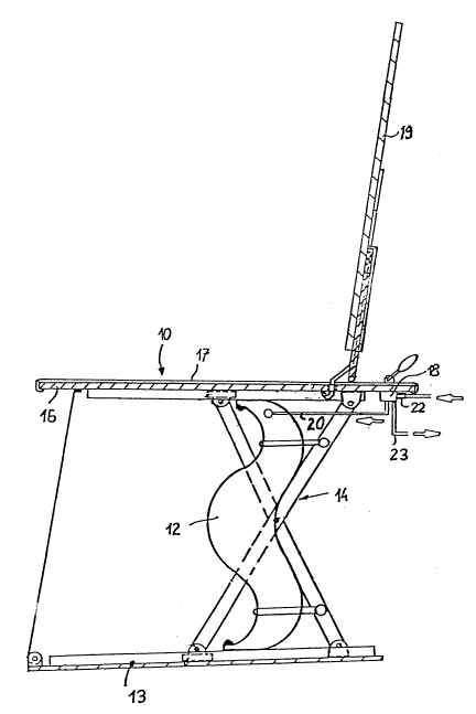
A bath lift 10 consists of a base frame or base structure 13
to which a hydraulic lifting hose 12 is fitted and which
supports a guide frame 14. The latter, in turn, supports and
4 2181285
guides a lifting plate 16 with a cushion mat 17. The top of
the hydraulic lifting hose 12 is fitted to the underside of
the lifting plate 16. Protruding out of an opening, which is
not illustrated, in the lifting plate 16 is a manual lever of
a manual control valve 18, which has two operating positions
and a central neutral position. The hydraulic lifting hose 12
is connected to the manual control valve 18 via a connection
line 20. The manual control valve 18 additionally features a
coupling element 22 as the pressure-water supply connection,
and a drain line 23. In one operating position of the manual
control valve 18, the hydraulic lifting hose 12 is connected
via the connection hose 20 to the pressure-water supply
connection, so that the hydraulic lifting hose is filled and
the lifting plate 16 is raised. In the other operating
position, the hydraulic lifting hose 12 is connected to the
drain line 23, so that the lifting plate 16 moves downwards.
In the neutral central position, the hydraulic lifting hose
12 is shut off both from the supply connection and from the
drain line.
The lifting plate 16 is provided with a back rest 19, the
angle of inclination of which is adjustable. In Figure 1, a
mechanical adjusting mechanism is provided at the rear of the
back rest 19. As an alternative, a back rest 19 with a
hydraulic actuator may be used, for example in the form of a
hose element located across the back rest 19 and supported by
the lifting plate 16, against which hose element an arm
located towards the rear of the back rest 19 is supported and
can be connected to the pressure-water supply via a delivery
and drain line connected to a further manual control valve
which is not illustrated.
Figure 2 then shows an underside view of the lifting plate 16
in its basic form, of which the coupling element 22 forming
the supply connection is connected via a hose element 24 to
the manual control valve 18, which in turn is connected via
the connection hose 20 to the hydraulic lifting hose 12. The
hose for the hand-held shower attachment is removed from the
2181285
bath tub tap fitting, which is not illustrated, and replaced
by a connection hose which is connected to the coupling
element 22. The bath lift 10 is then ready for operation.
As is apparent from FIG. 2, the manual control valve 18
engages in an approximately rectangular, oblong opening 26
which is located close to a longitudinal side of the lifting
plate 16. An opening 28 of the same design is located on the
opposite longitudinal side of the lifting plate 16 in mirror
arrangement to the longitudinal centreline of the lifting
plate 16. On both sides of the openings 26, 28 are located
fixing holes 30. The hole patterns of the fixing holes 30 of
both openings 26, 28 are identical. The coupling element 22
is likewise bolted to the underside of the lifting plate 16
by means of bolts passing through the fixing holes 32. On the
right-hand side of the lifting plate 16 shown in FIG. 2 are
also located fixing holes 32, once again in a book-
symmetrical arrangement relative to the holes 32 on the
opposite side. The manual control valve 18 and the coupling
element 22 may, therefore, be fitted either to the left or
the right-hand side of the lifting plate as required. The
conversion work may also be subsequently performed with ease
by any layman. The cushion mat 17 merely needs to be turned
around, whereupon it will also fit over the manual control
valve 18 where this is located on the other side of the plate
16.
Figure 3 illustrates the first expansion stage of the basic
module shown in Figure 2. This expansion stage comprises a
manifold 34 with a coupling nipple 36 which constitutes the
new supply connection, a hose element 38 with connection
nipple 40 which, together with coupling element 22, forms a
plug-in coupling assembly, and a connection fitting 42. The
manifold 34 is secured by means of three bolts to the fixing
holes 44 which are also already provided in the basic outfit
as per FIG. 2. The connection line coming from the bath tub
fitting is secured to the plug-in nipple 36 in accordance
with FIG. 3. The connection fitting 42 is self-sealing and is
6 218128~
only opened on insertion of a plug-in nipple of a connection
hose. With the expansion stage as per FIG. 3, the bath lift
10 can thus be operated as in the case of the basic module,
the connection fitting 42 providing a further pressure-water
supply option, e.g. for the connection of a shower attachment
hose or of a connection hose for a hydraulic back rest
adjuster.
Figure 4 shows an alternative expansion stage to that
according to FIG. 3. This expansion stage likewise comprises
a manifold 35, the design of which is somewhat different from
that of the manifold according to FIG. 3 inasmuch as it
features a central connection nipple 36 and two fixed outlet
lines 38, 46. Line 38 is, in turn, connected via a connection
nipple to the coupler 22, and the hose line 46 ends in a
second manual control valve 48 which is bolted in the free
opening 28 of the lifting plate 16. This second manual
control valve features at the outlet end a connection fitting
50. The second manual control valve 48 is a shut-off valve.
The hose of a hand-held shower attachment may thus be
connected to connection fitting 50. The hand-held shower
attachment is activated by operation of the second manual
control valve 48.
FIG. 5 shows a variant which corresponds to that according to
FIG. 3, but without the coupling arrangement with coupling
components 22, 40. This version is employed if a lift is
ordered to include the first expansion stage. The manifold 34
is the same as in the embodiment according to FIG. 3.
However, it is permanently connected to the first manual
control valve 18 by hose 39. Hose element 24 is therefore
omitted.
FIG. 6 shows a connection arrangement corresponding to that
of FIG. 4 for the case where the bath lift is ordered from
the manufacturer with an alternative expansion stage. Here,
too, the hose coupling arrangement 22, 40 is omitted.
7 2I8128~
An embodiment not illustrated features a manifold which
constitutes a combination of the two illustrated manifolds
34, 35, in which namely manifold 34 exhibits connection hoses
38/39 and 46 on the two sides respectively, so that the bath
lift 10 possesses two connection fittings 42, 50 so as to
enable, for example, a shower attachment hose and a
connection hose for the hydraulic angle adjustment system of
the back rest to be connected.
The second manual control valve 48 according to Figures 4 and
6 is - because it is designed as a pure shut-off valve -
suitable for the connection of a hand-held shower attachment.
If, on the other hand, the hydraulic actuator for the back
rest adjustment system is to be connected, a second manual
control valve in the form of a three-way directional valve is
required corresponding to that which constitutes the first
manual control valve 18.