Language selection

Search

Patent 2181441 Summary

Third-party information liability

Some of the information on this Web page has been provided by external sources. The Government of Canada is not responsible for the accuracy, reliability or currency of the information supplied by external sources. Users wishing to rely upon this information should consult directly with the source of the information. Content provided by external sources is not subject to official languages, privacy and accessibility requirements.

Claims and Abstract availability

Any discrepancies in the text and image of the Claims and Abstract are due to differing posting times. Text of the Claims and Abstract are posted:

  • At the time the application is open to public inspection;
  • At the time of issue of the patent (grant).
(12) Patent: (11) CA 2181441
(54) English Title: FILTER ELEMENT FOR THE SEPARATION OF DUST PARTICLES FROM A GAS
(54) French Title: ELEMENT FILTRANT DESTINE A SEPARER LES PARTICULES DE POUSSIERE D'UN GAZ
Status: Deemed expired
Bibliographic Data
(51) International Patent Classification (IPC):
  • B01D 29/27 (2006.01)
  • B01D 46/02 (2006.01)
  • B01D 46/42 (2006.01)
(72) Inventors :
  • BORKENT, ALBERT (Netherlands (Kingdom of the))
  • KUIPER, ERIK (Netherlands (Kingdom of the))
  • VAN VREELAND, SANDER GODFRIED (Netherlands (Kingdom of the))
(73) Owners :
  • FILTRAIR B.V. (Netherlands (Kingdom of the))
(71) Applicants :
(74) Agent: NORTON ROSE FULBRIGHT CANADA LLP/S.E.N.C.R.L., S.R.L.
(74) Associate agent:
(45) Issued: 1999-02-09
(86) PCT Filing Date: 1995-01-13
(87) Open to Public Inspection: 1995-07-20
Examination requested: 1996-11-28
Availability of licence: N/A
(25) Language of filing: English

Patent Cooperation Treaty (PCT): Yes
(86) PCT Filing Number: PCT/EP1995/000118
(87) International Publication Number: WO1995/019215
(85) National Entry: 1996-07-17

(30) Application Priority Data:
Application No. Country/Territory Date
94200091.0 European Patent Office (EPO) 1994-01-15

Abstracts

English Abstract


Filter element for the separation of dust particles from a gas or air flow, comprising a number of filter pockets and a main support
frame, the open mouths edges of the filter pockets being interconnected to the main support frame and its interconnecting traversing ribs,
characterized in that the main support frame (2) comprises interfitting subframes (8, 9) which are detachably connected one to another and
to each and all of the filter pockets (3).


French Abstract

Cet élément filtrant destiné à séparer les particules de poussière d'un gaz ou d'un écoulement d'air, comprend un certain nombre de poches filtrantes ainsi qu'un cadre de support principal, les bords des ouvertures des poches filtrantes étant reliées au cadre de support principal et aux montants de raccordement transversaux de celui-ci, cet élément filtrant étant caractérisé en ce que le cadre de support principal (2) comprend des cadres secondaires (8, 9) reliés de façon détachable par ajustement les uns dans les autres et reliés également de façon détachable à chacune des poches filtrantes (3).

Claims

Note: Claims are shown in the official language in which they were submitted.


Claims:


1. A filter element for the separation of dust
particles from a gas or air flow, comprising a number of
filter pockets and a main support frame, the open mouths
edges of the filter pockets being interconnected to the
main support frame and its interconnecting traversing
ribs, characterized in that the main support frame
comprises interfitting subframes which are detachably
connected one to another and to the filter pockets with
detachable connection means, wherein open edges of the
filter pockets are imprisoned between opposed surfaces
of the interfitting subframes.

2. A filter element according to Claim 1,
characterized in that said interfitting subframes
comprise an interior subframe and an exterior subframe,
the periphery of the interior subframe to which the
filter pockets are connected, comprising a number of
protrusions whereas the exterior subframe is provided
with a corresponding number of receiving openings
whereas while interfitting the subframes into the main
support frame, the protrusions are interlockingly
engaged by each of the receiving openings, preferably by
means of a snapping action, whereas simultaneously the
open edges of the filter pockets are leakfree and
tightly wedged in the narrow slit between opposed
surfaces of the subframes.

3. A filter element according to Claims 1 or 2,
characterized in that in a cross section traversing ribs
and a frame of the interior subframe are of trapezoidal
shape and are provided with holes for the insertion of a
security means.


4. A filter element according to Claims 1 or 2,
characterized in that in a cross section traversing ribs
and a frame of the exterior subframe are of reversed
gutterlike trapezoidal shape, its longest basis being
open.

5. A filter element according to Claims 1 to 4,
characterized in that in a cross section traversing ribs
of a subframe have a smaller cross section than the
frame itself has.

6. A filter element according to Claims 1 to 5,
characterized in that the main support frame has been
molded from a granulable resin which is of a recyclable
type.

7. A filter element according to Claims 1 to 6,
characterized in that the main support frame is provided
with a number of security locks which are at least
provided in each of traversing ribs of a subframe.

8. A filter element according to Claim 7,
characterized in that each lock comprises a magnetically
operating securing lock pin.

9. Method for assembling a filter element
according to Claims 1 to 8, characterized in that in a
first operational step the filter pockets are positioned
upon a workbench having recesses to accommodate the
filter pockets with their open edges fixed to the
interior subframe while in a second operational step the
exterior subframe is positioned over the interior
subframe and forcibly pressed down to interlock the
protrusions of the interior subframe with the receiving


11
openings of the exterior subframe one and the other in
such a way that these frame portions are interconnected
firmly and flatly thereby tightly interwedging the
filter pocket edges leakfree in the assembled main
support frame and in a third operational step to provide
upon the traversing ribs of the main support frame for a
number of security locks, in such a way that untimely
and/or unauthorized loosening of the interassembled
subframes and its filter pockets is thereby prevented.

10. Method for disassembling a filter element
according to Claims 1 to 8, characterized in that in a
first operational step the security locks are unlocked
when the filter element has been placed upon a
workbench, preferably by a number of built-in magnets
provided at the location of a security pin lock to
disengage the locked pins whereas either in the same
operational step or during the next operational step one
or more wedge shaped knife tools are forcibly interposed
in the narrow slit between adjacent subframe parts at
both sides of a protrusion where the latter is
interlockingly engaged held by a receiving opening
causing the protrusion to be released from the receiving
opening whereafter the pocket filters can easily be
removed from the disengaged interior subframe with
respect to the exterior subframe.

11. A filter element for the separation of dust
particles from a gas or air flow, comprising:
a number of filter pockets; and
a main support frame;
the open mouth edges of said filter pockets
being interconnected to said main support frame and its
interconnecting traversing ribs wherein said main


12
support frame comprises interfitting interior and
exterior subframes which are detachably connected one to
another and to each and all of said filter pockets,
characterized in that the periphery of the interior
subframe to which said filter pockets are connected,
comprises a number of protrusions and the exterior
subframe is provided with a corresponding number of
receiving openings for interfitting said subframes into
said main support frame, the protrusions being
interlockingly engaged by each of said receiving
openings by means of a snapping action, such that
simultaneously the open edges of said filter pockets are
leak free and tightly wedged between opposed surfaces of
said subframes.

12. A filter element according to Claim 11,
wherein in a cross section said traversing ribs and the
frame of said interior subframe are of trapezoidal shape
and the traversing ribs of said interior subframe are
provided with holes for the insertion of a security
means.

13. A filter element according to Claim 11,
wherein in a cross section said traversing ribs and the
frame of said exterior subframe are of reversed
trapezoidal shape, its longest base being open.

14. A filter element according to Claim 11, such
that, in cross section, said traversing ribs of said
interior and exterior subframes are smaller than said
frame of said interior and exterior subframes in cross
section.

13
15. A filter element according to Claim 12, such
that, in cross section, said traversing ribs of said
interior subframe are smaller than said frame of said
interior subframe in cross section.

16. A filter element according to Claim 13, such
that, in cross section, said traversing ribs of said
exterior subframe are smaller than said frame of said
exterior subframe in cross section.

17. A filter element according to Claim 11,
wherein said main support frame has been molded from a
granular resin which is of a recyclable type.

18. A filter element according to Claim 12,
wherein said main support frame has been molded from a
granular resin which is of a recyclable type.

19. A filter element according to Claim 13,
wherein said main support frame has been molded from a
granular resin which is of a recyclable type.

20. A filter element according to Claim 11, such
that said main support frame is provided with a number
of security locks which are at least provided in each of
said traversing ribs.

21. A filter element according to Claim 12, such
that said main support frame is provided with a number
of security locks which are at least provided in each of
said traversing ribs.

22. A filter element according to Claim 13, such
that said main support frame is provided with a number

14

of security locks which are at least provided in each of
said traversing ribs.

23. A filter element according to Claim 20, such
that said lock comprises a magnetically operating
security lock pin.

24. A filter element according to Claim 11,
wherein the plurality of subframes forming part of the
main support frame comprises:
an interior subframe with traversing ribs such
that in a cross section said traversing ribs and the
frame of said interior subframe are of trapezoidal shape
and the traversing ribs of the interior subframe are
provided with holes for the insertion of a security
means and
an exterior subframe with traversing ribs such
that in a cross section said traversing ribs and the
frame of said exterior subframe are of reversed
trapezoidal shape, its longest base being open.

25. A filter element for the separation of dust
particles from a gas or air flow, comprising:
a number of filter pockets; and
a main support frame;
the open mouth edges of said filter pockets
being interconnected to said main support frame and its
interconnecting traversing ribs wherein said main
support frame comprises interfitting interior and
exterior subframes which are detachably connected one to
another and to each and all of said filter pockets,
characterized in that the periphery of the exterior
subframe to which said filter pockets are connected,
comprises a number of protrusions and the interior


subframe is provided with a corresponding number of
receiving openings for interfitting said subframes into
said main support frame, the protrusions being
interlockingly engaged by each of said receiving
openings by means of a snapping action, such that
simultaneously the open edges of said filter pockets are
leak free and tightly wedged between opposed surfaces of
said subframes.

26. A filter element according to Claim 25,
wherein in a cross section said traversing ribs and the
frame of said interior subframe are of trapezoidal shape
and the traversing ribs of said interior subframe are
provided with holes for the insertion of a security
means.

27. A filter element according to Claim 25,
wherein in a cross section said traversing ribs and the
frame of said exterior subframe are of reversed
trapezoidal shape, its longest base being open.

28. A filter element according to Claim 25, such
that, in cross section, said traversing ribs of said
interior and exterior subframes are smaller than said
frame of said interior and exterior subframes in cross
section.

29. A filter element according to Claim 26, such
that, in cross section, said traversing ribs of said
interior subframe are smaller than said frame of said
interior subframe in cross section.

16

30. A filter element according to Claim 27, such
that, in cross section, said traversing ribs of said
exterior subframe are smaller than said frame of said
exterior subframe in cross section.

31. A filter element according to Claim 25,
wherein said main support frame has been molded from a
granular resin which is of a recyclable type.

32. A filter element according to Claim 26,
wherein said main support frame has been molded from a
granular resin which is of a recyclable type.

33. A filter element according to Claim 27,
wherein said main support frame has been molded from a
granular resin which is of a recyclable type.

34. A filter element according to Claim 25, such
that said main support frame is provided with a number
of security locks which are at least provided in each of
said traversing ribs.

35. A filter element according to Claim 26, such
that said main support frame is provided with a number
of security locks which are at least provided in each of
said traversing ribs.

36. A filter element according to Claim 27, such
that said main support frame is provided with a number
of security locks which are at least provided in each of
said traversing ribs.

17
37. A filter element according to Claim 34, such
that said lock comprises a magnetically operating
security lock pin.

38. A filter element according to Claim 25,
wherein the plurality of subframes forming part of the
main support frame comprises:
an interior subframe with traversing ribs such
that in a cross section said traversing ribs and the
frame of said interior subframe are of trapezoidal shape
and the traversing ribs of the interior subframe are
provided with holes for the insertion of a security
means and
an exterior subframe with traversing ribs such
that in a cross section said traversing ribs and the
frame of said exterior subframe are of reversed
trapezoidal shape, its longest base being open.

Description

Note: Descriptions are shown in the official language in which they were submitted.


j_ WO 95/19215 PCT/EP95/00118
ZlB:1~41


FILTER ELEMENT FOR THE SEPARATION OF DUST PARTICLES FROM A GAS.

The invention relates to a fillerele",ent for the separation of dust particles
from a gas or air flow comprising a number of filter pockets and a main support
frame the open mouths edges of the filter pockets being ir~le~cGr"~ected to the
main support frame and its inte~cGn"ecting traversing ribs.

Such a fillerele" ,e"l mostly forming part of a large filtration system which
is provided with a number of filterelements e.g. in use for air supply installations
for ventilating applications in commercial buildings plants industrial installations
and painting booths is described in US patent 4 056 375. In this known art a
number of seK supporting relatively stiff filter pockets is undetachably connected
to a main support frame since this is immediately and materially i,lteyraLed with
edges of the nonwoven filter pockets by means of a foaming method.
After uti~ ;G" when the filter pockets are saturated with dust particles
and have to be replaced it is a great disadvantage that the main support frame
is not reusable and so it must be destroyed. Not only filter pockets have to be
replaced but i,ll,e,e,)tly also the i"le~,dled main support frames - also the
envi,o"",ent becGI"es ll"eatt:"ed bec~use the "~ale,ial of the filter pockets
can"ot simultaneously be recycled with the material of the main support frame -
and moreover heavily co, Itar~ ,atecJ filter pockets may be considered as falling
under cl,~",ical refuse for which recycling will not be applicable and for whichspecial reg~ ons for disposition are given.
O~er known ~iltldtion systems do not allow for an efficient separation of
raw",ale,ial neitl,er ",ecl,anically nor chemically of such int~yrdted filter pockets
from the main support frame so that the reuse of " ,alerials by a recycling process

WO 9S/19215 PCT/EP95/00118
~$~
is not feasible or practicable.

Another disadvantage of the prior art is involved with the voluminous space
required for storage and transport respectively bec~ ~se the inflexible shape of the
tillelele."ent particularly the imbedding of the filter pockets in its main support
frame does not allow for a reduction in volume merely by pressi"g the sides of
~dj~cent filter pockets together. At the most it will be possible to shelve two
filLelele",ents of the prior art identical in sizes into each other reversely while
making use of the wedged sp~ces of ~djacent stiff filter pockets. Transport costs
and storage costs remain so unduly affected.

The invention now provides for a novel filterelement which does not have
the dtore" ,entioned disadvantages thereby enabling a substantial increase in ths
usage values of the rl ,alerials involved and favourably contributing to present high
environmental sla"dards, at lower long term system costs. This is achieved in that
the main support frame comprises i, Ite, tilliny subframes 9) which are detachably
connected one to ~utl,er and to the filter pockets (3).
This filter element application will bring about the following advantages:
- the same main support frame is now reusable many times;
- less main support frames must be mechanically/chemically treated and
made fit for recycling which gives less environmental burden;
- sloraye and transport expenses are declease~ bec~se of the need for
less slor~e lldlls~,G-l and packing space now allowing for a sub~ ial
larger number of prefaL,icdte.l filter pockets and t,a",es e.g. in a large
sed~ Jht or airfreight COI tL;ner or truck. Pr~ctic~lly this means that
almost 4 times as many prefaLricdled novel tillerele "e, lt~ can be stored
compared with the prior art fillelele.llellts in the same volume of space.

~ WO 95119215 PCTIEP95/00118
'- 2181441

In a preferred embodiment of the invented filterelement the periphery of the
interior subframe to which the filter pockets are con, le- Led comprises a number
of protrusions wl,erdas the periphe,-y of the eALe,ior subframe is provided with a
cGr,esponding number of receiving openings whereas while i~lte~tiLLi~y the
subframes into the main support frame the protrusions are interlockingly
engaged by each of the receiving openings preferably by means of a snapping
action whereas simultaneously the open edges of the filter pockets are leakfree
and tightly wedged in the narrow slit left between opposed surfaces of the
subframes.
This way of interlocking engagement between the subframes and the
edges of the fi,ter pockets guara"Ldes during operating time a totally reliable
leakfree seal which is still improved in anuLher em, odi" ,e, It of the invention when
the main support frame is ~JrlitiG"ally and pretelably provided in the traversing
ribs with security locks. Under operation these locks give optimal effect against
heavy air or equivalent thrust loads. It has been found that a security lock
operating under a may"etic force is a highly prefer,ed embo.li",e,lt.

An efficient method for the assembly of the invented filterelement is
chara~ Leri~ed in that in a first opelaLiGnal step the fi,ter pockets are positioned
upon a wor,~be"~:l, provided with rdcesses for acc~",odaLi"y the filter pockets
with their open edges fixed to the i, lt,~, ior subh ~1" ,e while in a secG"d operdLiGnal
step the eAle,ior su,Jhdl"e is ,~ositiG"ecJ over the i"te,ior su,Jhd",a and forcibly
pressed down to interlock the protrusions of the illtdrior subframe with the
rece;v;. ,9 openings of the eAle, ior subframe one and the other in such a way that
these frame pGILiolls are interc~l"le~Ldd firmly and flatly Ll,e,e, y tightly
i"te, ~ gi"y the fi,ter ,uoch~t~ le~ktlee in-the assembled main support frame and
in a third ope, aliGnal step to provide upon the traversing ribs of the main support


frame for a number of security locks~ such a way that
undesired and/or unauthorized loosening of the
interassembled subframes and the filter pockets is thereby
prevented.

Another efficient method for disassembling an
invented filter element to replace the filter pockets, is
characterized in that in a first operational step the
security locks are unlocked when the filter element has
been placed upon a workbench, preferably provided with a
number of built-in magnets at the location of a security
pin lock to disengage the locked pins whereas either in
the same operational step or during the next operational
step one or more wedge shaped knife tools are forcibly
interposed in the narrow slit left between adjacent
subframe parts at both sides of a protrusion where the
latter is interlockingly engaged and held by a receiving
opening causing the protrusion to be released from the
receiving opening whereafter the pocket filters can easily
be removed from the disengaged interior subframe from
which the exterior subframe can now be lifted away.

Therefore, in accordance with the present
invention, there is provided a filter element for the
separation of dust particles from a gas or air flow,
comprising a number of filter pockets and a main support
frame, the open mouths edges of the filter pockets being
interconnected to the main support frame and its
interconnecting traversing ribs, characterized in that
the main support frame comprises interfitting subframes
which are detachably connected one to another and to the
filter pockets with detachable connection means, wherein
open edges of the filter pockets are imprisoned between
opposed surfaces of the interfitting subframes.

4 4 ~
_ 4a


Also in accordance with the present invention,
there is provided a filter element for the separation of
dust particles from a gas or air flow, comprising:
a number of filter pockets; and
a main support frame;
the open mouth edges of said filter pockets
being interconnected to said main support frame and its
interconnecting traversing ribs wherein said main
support frame comprises interfitting interior and
exterior subframes which are detachably connected one to
another and to each and all of said filter pockets,
characterized in that the periphery of the interior
subframe to which said filter pockets are connected,
comprises a number of protrusions and the exterior
subframe is provided with a corresponding number of
receiving openings for interfitting said subframes into
said main support frame, the protrusions being
interlockingly engaged by each of said receiving
openings by means of a snapping action, such that
simultaneously the open edges of said filter pockets are
leak free and tightly wedged between opposed surfaces of
said subframes.

Still in accordance with the present
invention, there is provided a filter element for the
separation of dust particles from a gas or air flow,
comprising:
a number of filter pockets; and
a main support frame;
the open mouth edges of said filter pockets
being interconnected to said main support frame and its
interconnecting traversing ribs wherein said main
support frame comprises interfitting interior and


~;

~ 4
4b
._

exterior subframes which are detachably connected one to
another and to each and all of said filter pockets,
characterized in that the periphery of the exterior
subframe to which said filter pockets are connected,
comprises a number of protrusions and the interior
subframe is provided with a corresponding number of
receiving openings for interfitting said subframes into
said main support frame, the protrusions being
interlockingly engaged by each of said receiving
openings by means of a snapping action, such that
simultaneously the open edges of said filter pockets are
leak free and tightly wedged between opposed surfaces of
said subframes.

The invention will be further explained
hereinafter in the accompanying drawing whereby certain
characteristics and other advantages of the invention may
be brought forward.
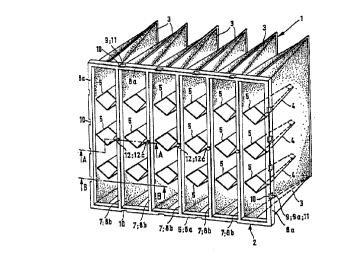
Fig. 1 is a front view, partly in perspective,
of a filter element according to the invention;
Fig. 2 is a partial cross section through the
main support frame along the line A-A of the filter
element in Fig. 1;
Fig. 3 is a partial cross section through the
exterior subframe along the line B-B in Fig. 1 and
Fig. 4 is a partial cross section through the
interior subframe along the line B-B in Fig. 1.


~ ~,

WO 95/19215 2 1 X 14 ~ I PCT/EP95/00118


The filterelement 1 comprises a main stiff support frame 2 and wedge
shaped filter pockets 3. These filterpockets 3 are preferably of the type havingselfsupporting characteristics which are realized by a.o. the application of
~ ned cloth ",alerials such as specially prepa,e.l nonwoven filter materials in
addition to appropriale d;sld"ce means 5, also of non-woven material positioned
along the depth of the filter pocket. The clisldr,ce means 5 are welded inside in
each filter pocket 3 at its both sides along lines 4 and bec~use of their diamond
shape their opposite flanks tend to flatten hori~ontdlly under load pressure
1 û ll ,ereby eAe, lil ~y a stabilizing force upon the operating vertical position of the filter
pocket and so avoiding blowing up of the filter pocket wl,ereas these distance
means tend to fold up vertically (in Fig. 1) in the event loose filter pockets are
piled up for storage.

The wedge shaped filter pockets 3 are generally manl~ctured from
~Gn~/Jven filter sheet ",ale,ial consisti"g of glass fibers or of synthetic fibers. The
a6sGrption rate for dust pallicles and the rate of ~:terliiG" are very favorable in
such " ,ale, ials.
The main support frame 2 comprises the frame 6 itself and traversing bars or ribs
7. The main support frame 2 see also Fig. 2, is built up of an e~ ior sub~,al"e
8 that snugly fits over an i,~trior su~,ame 9. In order to achieve a low flow
.esistance in the air stream ~I,ere;., it is installed and also to provide for an
i"cleased density automatic leak~ree seal in the ~"",resse~ edges of the
nonwoven filter pocket mouth " ,at~- ial it is favorable to give the combi. ~dliGn of
the sullfia",e 8 the frame pGlliGII 8a and the traversing bars 8b in a cross
se~AiGIl a trapezoidal shape leaving the basis 8c open; see also Fig. 3. In a
cross sectiGn the frame po. tiGI I 9a and the traversing bars 9b of the subfr m e 9
also have a trapezoidal shape and there are provided pin holes 9c (see Fig. 2)

WO 95/19215 PCT/EP95/00118

4 ~ 1


for the leakfree insertion of security means 12. In a preferred embodiment thereare provided on the periphery of the interior subframe 9 upon which the edges
at the mouth of the filter pocket are applied and at the circu,nfe,e"ce of the
frame portion 9a Ll ,ereof a number of protrusions 11 which can be locked by a
snapping movement into corresponding receiving openings 10 which are
provided in the periphery of the exla,ior subframe 8. As a result both subframes8 and 9 can be i,ltercon"e~Lad while exe,li"g pressure for assembling and the
rigid connection so obtained results in a firm and smooth and rigidly flat
assembly of this main support frame 2.
The filter pockets 3 having selfsuppG, lir)g characteristics are each applied to the
interior subframe 9 by means of their edge of its open ended mouth i.e. around
the traversing bars or ribs 9b and are loosely fitted to the frame portion 9a.
The exterior subframe 8 is placed over the interior subframe 9 to which the filter
pockets 3 are loosely fitted and in a favorable embodiment except for its
i,lLe.co"ne~Lion by means of the i"te,lochi"g structure of protrusions 11 and
receiv~ng openings 10 provided on the subframes 8 and 9 respectively
acldilio,)ally only secured andleakfree wedged in with security means 12 for
i,ltercor",ecting the subfid,.,e 9 and the filter pockets 3 thereby obtaining after
its assembling a leak~ae and reliable fillarele",e.,l.
In a pr~r-ad embodiment the security means cGnsisl of a soc~lle~ magnetically
operaled security pins known in the art for anti-theft devices of textile consumer
goods. These are yellelally cor"pose.l of a resin head piece 12a internally
provided with ele--,ents to mayn~ically lock a (steel)pin 12b that is protruded
through the " ,aterial to be secured and locked, this pin being provided with a flat
head piece 12c. However the pin can only be ~"agnt:tically unlocked II,elel y
,e'oqsng the filter pochets from the jointly assembled eALa,ior and inte,ior
subh~"es 8 and 9 ,esp~;ti~ely and Ll,a,e6y the filter pocket edges from the
traversing ribs and so enabling easy replace" ,e, It of the pock~t filter cloth inserts.

~ WO 95119215 PCT/~;~55J'~G118
~814~41

r, ~e, ably the rigid main support frame 2 composed of both subframes 8 and 9,
is manufactured from a polyamide which is extremely durable, rigid, and can be
granulated and which can be re-utilized by means of a recycling process, it being
impact-,esisla"l, thermically stable, having a fracture free surface; it can be easily
injection molded and besides it does not contain substances which are
environmentally undesirable.
To facilitate an efficient way of assembling and dis~sel "bling after the lifetime for
of the i"se, led pocket filterelement has expired, it is proposed to make use of a
workbench. r~efe,ably such a workbench should be provided with supporting
means for the i"l~:rior subframe 9 and should be provided with recesses for the
filter pockets in order to position the edges of the filterpockets upon the relevant
subframe portions and it should also COI ,l~i" SUppGI Liny means for the traversing
ribs. For interlocking the subframes one upon the other frame, whereby the edgesof the filter pockets are i"terenyaged by opposite su~,d",e wall portions;
pressure means may also be provided on the workbench to force the leakfree
compressed and wedged ",dltlial into a leah~lee airseal. To r~ sse",ble the
r,lle,element for replacement of the filter pockets it will be pre~erle~ to use a tool
frame which is provided with speci~l magnets at the location of each security pin
to unlock all of them simulLd"eously. The inlel locking engagement between the
subframes could be easily unlocked while using a row of u~slanJi"g wedge
shaped V-shaped tools which can penetraLe in the narrow slit at both sides of the
protrusion in the frame assembly. After a slight pen~dlion of the tool, which will
cause the protrusion 11 to become unlocked from its cGnesponding receiving
opening 10, the eAl~l ior subh dl) ,e 8 can be easily Imed from the i, ~rior subframe
9 to replace the pocket filter insert.
The invention provides for a very rigid main frame structure whereas yet the
single subf~d"les 8 and 9 lespe~ /ely are in itself rather flexible and so the
fillerele. "e, It meets very high requirements for rigidity, reliability and flow stability.

WO 95/19215 PCTIEP95/00118
218144 ~ --

P sides, the main frame structure can be used at least 10 times or much more
compared with prior art r,llerele" ,ents, thereby resulting in sl lh~ltial service cost
reduction aspects in usage, storage and ~ar,sp~,t~lio"
For an expert in this type of rlllerele."ents as desc,ibed here, it is clear that
several cGr,~t,uctional features may be amended without deviating from the full
potential scope of this invention.

Representative Drawing
A single figure which represents the drawing illustrating the invention.
Administrative Status

For a clearer understanding of the status of the application/patent presented on this page, the site Disclaimer , as well as the definitions for Patent , Administrative Status , Maintenance Fee  and Payment History  should be consulted.

Administrative Status

Title Date
Forecasted Issue Date 1999-02-09
(86) PCT Filing Date 1995-01-13
(87) PCT Publication Date 1995-07-20
(85) National Entry 1996-07-17
Examination Requested 1996-11-28
(45) Issued 1999-02-09
Deemed Expired 2006-01-13

Abandonment History

There is no abandonment history.

Payment History

Fee Type Anniversary Year Due Date Amount Paid Paid Date
Application Fee $0.00 1996-07-17
Maintenance Fee - Application - New Act 2 1997-01-13 $100.00 1996-07-17
Registration of a document - section 124 $0.00 1996-10-10
Maintenance Fee - Application - New Act 3 1998-01-20 $50.00 1998-01-12
Final Fee $150.00 1998-10-29
Maintenance Fee - Application - New Act 4 1999-01-13 $50.00 1999-01-11
Maintenance Fee - Patent - New Act 5 2000-01-13 $75.00 1999-12-16
Maintenance Fee - Patent - New Act 6 2001-01-15 $75.00 2001-01-10
Maintenance Fee - Patent - New Act 7 2002-01-14 $75.00 2001-12-20
Maintenance Fee - Patent - New Act 8 2003-01-13 $75.00 2003-01-03
Maintenance Fee - Patent - New Act 9 2004-01-13 $75.00 2003-12-29
Owners on Record

Note: Records showing the ownership history in alphabetical order.

Current Owners on Record
FILTRAIR B.V.
Past Owners on Record
BORKENT, ALBERT
KUIPER, ERIK
VAN VREELAND, SANDER GODFRIED
Past Owners that do not appear in the "Owners on Record" listing will appear in other documentation within the application.
Documents

To view selected files, please enter reCAPTCHA code :


To view images, click a link in the Document Description column. To download the documents, select one or more checkboxes in the first column and then click the "Download Selected in PDF format (Zip Archive)" or the "Download Selected as Single PDF" button.

List of published and non-published patent-specific documents on the CPD .

If you have any difficulty accessing content, you can call the Client Service Centre at 1-866-997-1936 or send them an e-mail at CIPO Client Service Centre.


Document
Description 
Date
(yyyy-mm-dd) 
Number of pages   Size of Image (KB) 
Description 1998-04-22 10 431
Claims 1998-04-22 9 315
Cover Page 1996-10-28 1 13
Abstract 1995-07-20 1 33
Description 1995-07-20 8 246
Claims 1995-07-20 3 80
Drawings 1995-07-20 2 55
Cover Page 1998-12-11 1 59
Representative Drawing 1998-12-11 1 25
Representative Drawing 1997-07-02 1 7
Correspondence 1998-10-29 1 57
Correspondence 1998-01-20 3 57
Fees 1996-07-17 1 45
PCT 1996-07-17 5 148
Prosecution-Amendment 1997-03-10 1 28
Prosecution-Amendment 1996-11-28 9 296
Prosecution-Amendment 1997-03-17 1 43
Prosecution-Amendment 1997-12-03 4 146
Prosecution-Amendment 1997-06-03 2 62
Correspondence 1996-09-03 1 20
Correspondence 1996-09-20 1 11
Assignment 1996-08-29 2 108
Assignment 1996-07-17 7 310
Correspondence 1997-12-05 1 26
Correspondence 1996-09-20 1 19