Note: Descriptions are shown in the official language in which they were submitted.
95P 7491
~t~~~~~
,~y~tem and Method for R~gulat9n~elivered Radiation in a Radiation-Emittine
BACKGROUND OF THE INVENTION
Field of the Invention
The invention relates to a radiation-emitting device, and particularly to a
system and a method for regulating the radiation delivered to an object in a
radiation
treatment device.
DetcriRtion of the Related A~ _.
Radiation-emitting devices are generally known and used, for instance as
radiation therapy devices for the treatment of patients. A radiation therapy
device
generally comprises a gantry which can be swiveled around a horizontal axis of
rotation in the course of a therapeutic treatment. A linear accelerator is
located in the
gantry for generating a high- energy radiation beam for therapy. This high
energy
radiation beam can be an electron radiation or photon (X-ray) beam. During
treatment, this radiation beam is trained on one zone of a patient lying in
the isocenter
of the gantry rotation.
In order to control the radiation emitted toward an object, a beam-shielding
device such as a plate arrangement or collimator is usually provided in the
trajectory
of the radiation beam between the radiation source and the object. This beam-
shielding device defines a field on the object to which a prescribed amount of
radiation is to be delivered.
The radiation delivered to an object may be analyzed into primary and
scattered components. The primary radiation is made up of the initial or
original
photons emitted from the radiation source, and the scattered radiation is the
result of
the photons scattered by the plate arrangement itself. The beam's radiation
output in
free space increases because of the increased collimator scatter, which is
added to the
primary beam. In other words, a point in the field is subjected not only to
direct
radiation, that is the primary component, but also to radiation that is
scattered from
the plate arrangement. The ratio of the radiation output in air with the
scatterer to-the
z~s~~z4
t
2
radiation output without thescatterer for a reference field (for instance 10 x
lOcm) is
commonly called the "output factor" or the collimator scatter factor. The
concept and
definition of the output factor are well understood in the art.
Thus, due to these scattered photons, the dose rate applied to the surface of
the
object changes dependent on the size of the opening in the plate arrangement,
that is,
on the field size. This means that the radiation emitted to the same spot, for
instance
in the center of the radiation beam onto the object, changes according to the
size of the
opening in the plate arrangement. When the plate arrangement shows only a
small
opening, then the accumulated dose at the same spot is less than the
accumulated dose
at the same spot when the opening is big.
The delivery of radiation by such a radiation therapy device is prescribed and
approved by an oncologist. Actual operation of the radiation equipment,
however, is
normally done by a therapist. When the therapist administers the actual
delivery of
the radiation treatment as prescribed by the oncologist, the device is
programmed to
deliver that specific treatment. When programming the treatment, the therapist
has to
take into consideration the output factor and has to adjust the dose delivery
based on
the plate arrangement opening in order to achieve the prescribed radiation
output on
the surface of the object. This adjustment can be made according to known
calculations, but the therapist normally has to do them manually, which can
easily
lead to errors. In the context of radiation therapy, a miscalculation can lead
to either a
dose that is too low and is ineffective, or that is too high and dangerous; a
large error,
for example, a misplaced decimal point, can be lethal.
What is needed is a system that eliminates this significant source of errors,
a
system that automatically adjusts the delivery of radiation to the object in
order to
make sure that the actually delivered radiation output is exactly the same as
the
desired radiation output, independent of the shape or size of the opening in
the plate
arrangement in the trajectory of the radiation beam.
21'~152~
1
~~~of the Invention
According to the invention, radiation output delivered to an object from a
radiation source, is regulated by generating a radiation beam using a
radiation source
having a variable radiation output. An irradiated field of the object is
defined. The
beam is shielded, preferably by an arrangement of at least one movable plate
between
the radiation source and the object. An output factor of the radiation is
thereby varied
according to the degree of shielding, in which the output factor is defined as
the ratio
between a reference radiation output of the beam when unshielded and an actual
radiation output of the beam as shielded. The radiation output is varied such
that the
output factor is constant regardless of the degree of$hielding. The output
factor is
preferably equal to unity.
In one embodiment of the invention, a reference radiation output value is
sensed for a reference plate position. Relative radiation output values are
then also
sensed for each of a plurality of plate positions covering a predetermined
range of
motion of each movable plate. A series of correction values is then generated
as a
predetermined comparison function of the reference radiation output value and
each of
the relative radiation output values. These correction values ate stored in a
memory.
The radiation output is then varied as a predetermined correction function of
nominal
dose signals and the correction value for each respective plate position of a
prescribed
treatment profile.
The system may be pre-set by generating a series of calibration signals and
field geometry parameters corresponding to a plurality of field sequences of a
predetermined treatment. The signals are then downloaded using a verification
and
auto-set circuit into the memory the series of calibration signals before an
actual
treatment.
CA 02181524 2006-10-03
20365-3602
- 3a
In accordance with one aspect of this invention,
there is provided a method for regulating the radiation
output delivered to an object from a radiation source,
comprising the following steps: generating a radiation beam
having a variable radiation output; defining an irradiated
field of the object; varying a degree of shielding of the
beam, an output factor of the radiation output thereby
varying according to the degree of shielding, in which the
output factor is defined as the ratio between a reference
radiation output of the beam when unshielded and an actual
radiation output of the beam as shielded; and varying the
radiation output such that the output factor is constant
regardless of the degree of shielding.
In accordance with another aspect of this
invention, there is provided a system for regulating the
radiation output delivered to an object from a radiation
source, comprising: a radiation source generating a
radiation beam having a variable radiation output; an
irradiated field of the object; beam-shielding means for
delimiting the output beam to at least one predetermined
irradiation field of the object; sensing means for sensing
radiation output of the shielded output beam and for
generating radiation output signals corresponding to
radiation output delivered to predetermined portions of the
field; a dose controller for varying a degree of shielding
of the beam; and processing means for generating and
applying to the dose controller set dose signals, comprising
nominal dose signals and dose correction factors, and for
thereby varying the radiation output such that an output
factor is constant regardless of the degree of shielding,
where the output factor is defined as a ratio between a
reference radiation output of the beam when unshielded and
an actual radiation output of the beam as shielded.
21~152~
4
Brief Description of the Drawing
Figure 1 is a schematic diagram of a radiation treatment device and a
treatment
unit constructed in accordance with the invention.
Figure 2 is a block diagram illustrating portions of a processing unit, a
control
unit and a beam generation system in the radiation treatment device of Figure
1.
Figure 3 shows the radiation output delivered from a radiation source to
various field sizes on an object according to the prior art.
Figure 4 shows the radiation output delivered from a radiation source to
various field sizes on an object according to the invention.
Figure 5 shows a diagram of output factors versus the sizes of an rectangular
field on an object, in which one dimension of the field is held constant.
detailed Descri ion
The invention is described below with primary reference to a system for
delivering X-ray radiation to a field of a patient, and for delimiting the
field using at
least one movable plate in the beam path from a radiation source. This is by
way of
example only. The invention may be used to regulate the delivery of any type
of
energy, for example, electrons (instead of X-rays), to any type of object (not
just a
human patient), provided the amount of energy delivered to the field can be
sensed or
estimated.
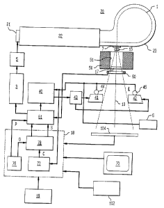
Figure 1 shows a radiation treatment device 2 of common design, in which
plates 4 and a control unit in a housing 9 and a treatment unit 100
constructed in
accordance with the principles of the invention are used. The radiation
treatment
device 2 comprises a gantry 6 which can be swiveled around a horizontal axis
of
rotation 8 in the course of a therapeutic treatment. Plates 4 are fastened to
a projection
of gantry 6. To generate the high-powered radiation required for the therapy,
a linear
accelerator is located in gantry 6. The axis of the radiation bundle emitted
from the
linear accelerator and gantry 6 is designated by 10. Electron, photon, or any
other
detectable radiation can be used for the therapy.
During the treatment the radiation beam is trained on a zone 12 of an object
13, for example, a patient who is to be treated, and who lies at the isocenter
of the
2181524
1
gantry rotation. The rotational axis 8 of gantry 6, the rotational axis 14 of
a treatment
table 16, and the beam axis 10 all preferably intersect in the isocenter. The
construction of such a radiation treatment device is described in general in a
brochure
"Digital Systems for Radiation Oncology", Siemens Medical Laboratories, Inc.
A91004-M2630-B358-Ol-4A00, September 1991.
The area of the patient that is irradiated is known as the field. As is well
known, the plates 4 are substantially impervious to the emitted radiation.
They are
mounted between the radiation source and the patient in order to delimit the
field.
Areas of the body, for example, healthy tissue, are therefore subjected to as
little
radiation as possible, and preferably to none at all. In the preferred
embodiment of the
invention, at least one of the plates is movable so that the distribution of
radiation
over the field need not be uniform (one region can be given a higher dose than
another); furthermore the gantry can preferably be rotated so as to allow
different
beam angles and radiation distributions without having to move the patient
around.
Neither or these features is necessary according to the invention: the
invention may
also be used with fixed-field devices (no movable plates), with constant
radiation
delivery rates, and with fixed-angle beams (no rotatable gantry).
Radiation treatment device 2 also includes a central treatment processing or
control unit 100, which is usually located apart from radiation treatment
device 2.
The radiation treatment device 2 is normally located in a different room to
protect the
therapist from radiation. Treatment unit 100 includes output devices, such as
at least
one visual display unit or monitor 70, and an input device such as a keyboard
19,
although data can be input also through data carriers, such as data storage
devices, or
an verification and recording or automatic set-up system 102, which is
described
below. The treatment processing unit 100 is typically operated by the
therapist who
administers actual delivery of a radiation treatment as prescribed by an
oncologist. By
utilizing the keyboard 19, or other input device, the therapist enters into a
control unit
76 of the treatment unit 100 the data that defines the radiation to be
delivered to the
patient, for example, according to the prescription of the oncologist. The
program can
also be input via another input device like a data storage device, through
data
6
transmission, or using the automatic set-up system 102. On the screen of a
monitor 70
various data can be displayed before and during the treatment.
Figure 2 shows portions of an illustrative radiation treatment device 2 and
portions of treatment unit 100 in more detail. An electron beam 1 is generated
in an
electron accelerator 20. Accelerator 20 comprises an electron gun 21, a wave
guide
22 and an evacuated envelope or guide magnet 23. A trigger system 3 generates
injector trigger signals and supplies them to injector 5. Based on these
injector trigger
signals, injector 5 generates injector pulses which are fed to electron gun 21
in
accelerator 20 for generating electron beam 1. Electron beam 1 is accelerated
and
guided by wave guide 22. For this purpose, a high frequency (HF) source (not
shown)
is provided which supplies radio frequency (RF) signals for the generation of
an
electromagnetic field supplied to wave guide 22. The electrons injected by
injector 5
and emitted by electron gun 21 are accelerated by this electromagnetic field
in waue
guide 22 and exit at the end opposite to electron gun 21 as electron beam 1.
Electron
beam 1 then enters a guide magnet 23, and from there is guided through a
window 7
along axis 10. After passing through a first scattering foil 15, the beam goes
through a
passageway 51 of a shield block 50 and encounters a second scattering foil 17.
Next,
it is sent through a measuring chamber 60, in which the dose is ascertained.
If the
scattering foils are replaced by a target, the radiation beam is an X-ray
beam. Finally,
aperture plate arrangement 4 is provided in the path of radiation beam 1, by
which the
irradiated field of the subject of investigation is determined. Aperture plate
arrangement 4 includes a pair of plates 41 and 42. As is described above, this
is just
one example of a beam-shielding arrangement that can be used in the invention.
The
invention will work with others also as long as there is an aperture plate
arrangement
that defines an irradiated field.
Plate arrangement 4 comprises a pair of aperture plates 41 and 42 and an
additional pair of aperture plates (not shown) arranged perpendicular to
plates 41 and
42. In order to change the size of the irradiated field the aperture plate can
be moved
with respect to axis 10 by a drive unit 43 which is indicated in Figure 2 only
with
respect to plate 41. Drive unit 43 comprises an electric motor which is
coupled to
plates 41 and 42 and which is controlled by a motor controller 40. Position
sensors 44
211524
and 45 are also coupled to plates 41 and 42, respectively, for sensing their
positions.
This is just one example of such a system. The invention will work with other
systems also, as long as there is a beam-shielding arrangement that defines an
irradiated field and as long as sensors are provided to indicate the field
size.
Motor controller 40 is coupled to a dose control unit 61 which includes a
dosimetry controller and which is coupled to a central processing unit 18 for
providing set values for the radiation beam for achieving given isodose
curves. The
output of the radiation beam is measured by a measuring chamber 60. In
response to
the deviation between the set values and the actual values, dose control unit
61
supplies signals to trigger system 3, which changes in a known manner the
pulse
repetition frequency so that the deviation between the set values and the
actual values
of the radiation beam output is minimized.
In such a radiation treatment device the output of the radiation beam
impinging on the surface of an object is dependent on the size of the opening
in plate
arrangement 4 and thus, on the size of the irradiated field on object 13.
In the following, for the sake of clarity and simplicity only, the invention
is
described in connection with the additional pair of plates (not shown) being
stationary. The invention may be used, however, in systems with additional
movable
plates, as long as suitable motor controllers and position sensors are
provided. When
plates 41 and 42 move apart from each other and thus widen the gap in-between,
the
actually delivered radiation output at any given spot on object 13, for
example in the
axis 10 of the radiation beam, increases due to the increased scatter, which
is added to
the primary beam.
In order to make sure that during treatment the radiation output at the same
spot on the surface of object 13 always equals the desired radiation output,
independent of the size of the opening, the output of the radiation beam must
be
adjusted according to the opening size.
Central processing unit 18 is connected, on the one hand, with the input
device, such as the keyboard 19, for inputting the prescribed delivery of the
radiation
treatment and, on the other hand, with a dose control unit 61 that generates
the desired
values of radiation for the controlling trigger system 3. Trigger system 3
then adapts
the pulse repetition frequency or other parameters in a corresponding,
conventional
manner. The ability to change the radiation output is generally known and it
is
particularly advantageous to use a digital dosimetry system because then it
can easily
be controlled by the digital output of central processing unit 18.
Figure 3 shows how the radiation output factor R depends on the size of the
opening between plates 41 and 42 and thus, on the field sizes F1 to Fn on
object 13
according to the prior art. Plates 41 and 42 are movable by drive unit 43 for
widening
or narrowing the opening, whereas, in this example, the other pair of plates
is assumed
to be stationary. As is described above, if the radiation output emitted by
radiation
source 17 is constant, the output factor R will increase as the field size
increases from
Fl to Fn.
Figure 4 shows the same configurations of plates 41 and 42, however,
according to the invention, in which the radiation output is regulated in such
a way
that the output factor remains constant despite a changing field size, that
is, despite
changes in the size of the openings in the plate arrangement 4. To this end,
the output
signals of position sensors 44 and 45, or any other signals indicative to the
size and/or
shape of the opening, are applied to central processing unit 18 for providing
adjusted
dose signals which take into account the size and/or shape of the openings and
thus
provide a constant output factor R. The radiation output is preferably
regulated so
that the output factor is kept at R=1 over the full range of motion of the
plates during
treatment. This implies that the radiation actually delivered is exactly equal
to the
radiation prescribed, despite a changing field size.
Note that, although the radiation output factor is held constant as the field
size
increases, this does not mean that the accumtdose must be constant over the
field. In fact, the reason for changing the field size at all during a
treatment is
normally to create a non-uniform pattern of radiation delivery over the field;
for
example, a wedge-shaped accumulated dose profile may be prescribed to deliver
more
radiation to an area of a tumor while avoiding adjacent healthy tissue. In
Figure 4, for
example, the accumulated dose in field F1 will be greater than the accumulated
dose
in the region between field F2 and F3. What the invention provides is a way to
make
sure that radiation output is precisely regulated to eliminate the uncertainty
introduced
z~~~~~
by scattering, that is, because of the output factor. Even more complicated
profiles
can be achieved by rotating the gantry as well as changing the field size.
Central processing unit 18 includes control unit 76 which controls the
execution of the program and which supplies position signals P for controlling
the
opening of plate arrangement 4 and nominal dose signals D (corresponding to
the
plate position that would be demanded using prior art methods, that is,
without regard
to output factor compensation) for adjusting the radiation output at the
output of
radiation source 17. A memory 77 is also provided in or is connected to the
central
processing unit 18 for supplying correction signals C, which the processing
unit uses
to adjust the radiation output dependent on the position signals P supplied
from
position sensors 44 and 45 in order to achieve the predetermined constant
output
factor.
The preferred arrangement of the memory unit is that, for each plate position
(field size), it has stored a corresponding dose correction signal C. The
memory thus
stores a table of correction factors. If more than one set of movable plates
is included
in the system, then the table will be correspondingly multi-dimensional, and
arranged
using any known data structure, so that a correction factor is available for
any
combination of plate positions.
Control unit 76 and memory 77 apply the dose and correction signals D and C,
respectively, to a combination circuit 78, which combines the values to
generate set
signals S. The set signals S are in turn applied to the dose control unit 61,
which sets
the radiation output.
The combination circuit 78 will depend on the form in which the correction
signals are generated and stored. Assume that the correction signals C are
stored as
additive offset. In this case, the combination circuit will be an adder which
adds the
correction signals C to dose signals D. This is the preferred embodiment,
since it is
simplest. If, however, the correction factors are multipliers (for example, an
increase
in radiation output by a factor of 102/100 would require a multiplicative
correction
signal of 100/102. Instead of storing actual values of the correction signals
C, it is
also possible to store the parameters of a correction function for the various
each field
sizes. The processing unit would then evaluate the function for each current
field size
218152
to
using the parameters stored in the memory, and would then generate the
correction
signals (additive or multiplicative) itself.
The correction signals are determined before actual treatment of a patient in
one or more calibration runs. To determine relative correction values, a
reference
surface (or line) is irradiated with a known reference plate position, and the
radiation
output over the surface is sensed by a conventional sensing device 104 (see
Figure 2),
which generates radiation output signals that are applied to the processing
unit 18.
The reference surface need not lie in the patient plane, although if it does
the
calibration will typically be easier and more accurate. Note that the
radiation output
may be sensed and stored for several different points of the surface, since
the output
may not be constant.
The plates are then moved to a new opening position, the radiation output is
sensed and stored, and so on, until radiation output values are stored for the
reference
surface over the entire range of motion of the plates. If more than one set of
movable
1 S plates is included, then calibration output values will be sensed and
stored for each
combination of plate positions; the number of combinations will depend on the
desired or required resolution.
Once a complete set of calibration output values is stored, each value is
compared with the value for the reference plate position (the reference output
value).
If additive offsets are chosen for the correction factors, then the difference
between
the sensed output values and the reference output value is stored. If
multiplicative
correction factors are chosen, then ratios are stored. Alternatively, any
known
function approximation method may be used to generate the parameters of an
approximating function of the additive or multiplicative correction factors
required.
Note that the correction factors obtained in the calibration steps just
described
will lead to a constant output factor, but not necessarily an output factor
R=1. This is
because the reference plate position itself may cause scattering, so that the
reference
radiation output value will not be equal to a known absolute radiation output
value. In
order to correct for this, one should preferably choose as the sensing device
104 a
device that is able to measure actual absolute radiation output, or one should
use
another conventional device to obtain an absolute output value for at least
one plate
. 2181524
11
position, which then is used as the reference plate position. In order to
ensure
accuracy over time, recalibration runs may be carried out, and new correction
factors
calculated and stored, according to a predetermined calibration schedule.
The output sensing device does not have to directly measure the absolute
output. Rather, it may measure dose rates for different plate positions, which
will
yield output values using known integration and offset techniques.
Figure 5 shows a diagram indicating in a solid line a constant output factor R
=
1 which is achieved according to the invention, and in dashed lines, an output
factor
according to the prior art. The horizontal axis shows one parameter of the
field size F
defined by plate arrangement 4 and the vertical axis shows the output factors
R. The
differences between the lines indicate the values of the correction signals C1
to Cn for
different field sizes F1 to Fn.
The invention makes it possible to adjust the output factor R, preferably to R
=
1, which means that if an oncologist advises a therapist to deliver a certain
radiation
output, the therapist does not have to take into account the respective output
factor R.
Then, the radiation treatment device automatically adjusts the radiation
output
according to the dimensions of the field. This reduces or wholly eliminates
the errors
induced when the therapist must calculated and compensate for variations in
the
output factor.
The invention can also be carried out in a radiation therapy device in which
at
least one aperture plate of plate arrangement 4 is movable during treatment.
Such a
device is described in U.S. Pat. No. 5,148,032. As described in this U.S.
Patent, in
such a radiation treatment device, various isodose curves can be easily
achieved
without a physical wedge being present in the trajectory of the beam. In this
case also
the correction values are added to the radiation output values to achieve a
given output
factor. Similar corrections may be used in devices that use a physical wedge.
In
either case, corresponding correction values C can be applied to the dose
signals D in
order to achieve a correct delivery of radiation to the object.
A "course" of radiation treatment may, and often does, have more than one
field, and may run over several different sessions. In some cases, hundreds of
different (and, in some cases, fixed) sequential fields are used during a
course, for
s
12
example, to provide proper irradiation of a field that has a complicated
geometry or
prescribed dose profile, to lessen discomfort to the patient, or to adjust the
field as a
tumor shrinks during treatment. The invention therefore also comprises an
optional
verification and recording or "auto set-up" system 102 (see Figure 2), which
stores
and downloads to the radiation system (via the CPU 18 or directly into the
memory)
the parameters, for example, of the geometry, of the various fields of the
course of
treatment, and/or the tables of correction factors that were derived during
earlier
calibration runs for the various fields.