Language selection

Search

Patent 2181571 Summary

Third-party information liability

Some of the information on this Web page has been provided by external sources. The Government of Canada is not responsible for the accuracy, reliability or currency of the information supplied by external sources. Users wishing to rely upon this information should consult directly with the source of the information. Content provided by external sources is not subject to official languages, privacy and accessibility requirements.

Claims and Abstract availability

Any discrepancies in the text and image of the Claims and Abstract are due to differing posting times. Text of the Claims and Abstract are posted:

  • At the time the application is open to public inspection;
  • At the time of issue of the patent (grant).
(12) Patent: (11) CA 2181571
(54) English Title: TOOL FOR FIXATION OF CABLE OR LINE
(54) French Title: OUTIL POUR LA FIXATION D'UN CABLE OU D'UNE LIGNE
Status: Deemed expired
Bibliographic Data
(51) International Patent Classification (IPC):
  • H02G 1/00 (2006.01)
  • B25B 27/00 (2006.01)
(72) Inventors :
  • HAGLUND, FINN AGNAR (Norway)
(73) Owners :
  • HAGLUND, FINN AGNAR (Norway)
(71) Applicants :
  • HAGLUND, FINN AGNAR (Norway)
(74) Agent: GOWLING WLG (CANADA) LLP
(74) Associate agent:
(45) Issued: 1999-08-24
(86) PCT Filing Date: 1995-01-25
(87) Open to Public Inspection: 1995-08-03
Examination requested: 1996-07-18
Availability of licence: N/A
(25) Language of filing: English

Patent Cooperation Treaty (PCT): Yes
(86) PCT Filing Number: PCT/NO1995/000018
(87) International Publication Number: WO1995/020834
(85) National Entry: 1996-07-18

(30) Application Priority Data:
Application No. Country/Territory Date
940280 Norway 1994-01-26

Abstracts

English Abstract


A tool for the fixation of a cable or line on a support by adherence means, the tool comprising
a pressure wheel (1) for guiding movement on and along said cable or line when mounted on a handle
(2). The circumference of the pressure wheel is adapted to the form and dimensions of the cable or line
in such a way that a predetermined pressure for adhesive fixation is applied with said guided movement.
The circumference of the pressure wheel suitably comprises a cylindric groove track (11) delimited on
each side by a flange for contact against the support when applying pressure for adhesive fixation during
the guided movement on and along the cable or line. The circumference of the pressure wheel may also
comprise a frustoconically shaped groove track (10) delimited at its narrower side by a flange to be in
contact with the support and at its wider side by a transverse surface to be supported against a wall surface
during the application of pressure for adhesive fixation during the guided movement on and along the
cable or line. Preferably the tool is implemented for exchange of the pressure wheel (1) in order to adapt
different pressure wheels to different lines and cables.


French Abstract

Outil pour la fixation par matière adhésive sur un support d'un câble ou d'une ligne. L'outil comporte un galet de pression (1) destiné à guider son déplacement sur ledit câble ou ladite ligne lorsque le galet est monté sur un manche (2). La circonférence du galet de pression est adaptée à la forme et aux dimensions du câble ou de la ligne de sorte qu'une pression prédéterminée assurant la fixation adhésive est appliquée au cours de ce déplacement guidé. La circonférence du galet de pression comporte avantageusement une voie à gorge cylindrique (11) délimitée de chaque côté par un bord venant au contact du support lors de l'application de la pression de fixation adhésive au cours du déplacement guidé sur le câble ou la ligne. La circonférence du galet de pression peut également comporter une voie à gorge tronconique (10) délimitée du côté étroit par un bord venant au contact du support, et du côté plus large par une face transversale destinée à s'appuyer contre la surface d'un mur lors de l'application de la pression de fixation adhésive au cours du déplacement guidé sur le câble ou la ligne. De préférence, l'outil est adapté pour permettre le remplacement du galet de pression (1) de manière à adapter différents galets de pression aux différents types de câble et de ligne.

Claims

Note: Claims are shown in the official language in which they were submitted.


CLAIMS
1. Tool for the fixation of a cable or line on a support by
adherence means, the tool comprising a pressure wheel (1) for
guided movement on and along said cable or line when mounted
on a handle (2)
characterized in that the circumference of the pressure wheel
is adapted to the form and dimensions of the cable or line in
such a way that a predetermined pressure for adhesive fixation
is applied with said guided movement.
2. Tool as claimed in claim 1,
characterized in that the circumference of the pressure wheel
comprises a cylindric groove track (11) delimited by flanges
to be in contact with the support when applying pressure for
adhesive fixation during the guided movement on and along the
cable or line.
3. Tool as claimed in claim 1,
characterized in that the circumference of the pressure wheel
comprises a frustoconically shaped groove track (10) delimited
at its narrower side by a flange to be in contact with the
support and at its wider side by a transverse surface to be
supported against a wall surface during the application of
pressure for adhesive fixation during the guided movement on
and along the cable or line.
4. Tool as claimed in any of the claims 1-3,
characterized in that it is implemented for exchange of the
pressure wheel (1) for the adaption of different pressure
wheels to different lines and cables.
5. Tool as claimed in claim 4,
characterized in that the pressure wheel is connected with an
anchor pin (3) having an associated snap lock (4) at one end.
6. Tool as claimed in claim 5,
characterized in that the tool handle (2) has an internally

6

threaded fixation hole (5) for the insertion of a screw for
the snap lock (4).
7. Tool as claimed in any of the claims 1-6,
characterized in that the handle comprises a guide spindle (6)
having a through passage (7) for the guidance of the anchor
pin (3) to the snap lock (4).
8. Tool as claimed in any of the claims 1-7,
characterized in that the handle is provided with fixation
grooves (8) for connection with an extension rod.
9. Tool as claimed in any of the claims 1-8,
characterized in that the tool handle (2) is formed with an
impact surface (9).
10. Tool as claimed in any of the claims 1-9,
characterized in that the handle (2) is curved for providing a
tapering (12) towards its end for the fixation of the
exchangeable pressure wheels (1).

Description

Note: Descriptions are shown in the official language in which they were submitted.


WO 9512083-1 2 ~ 8 ~ ~ 7 1 PCT/N09S100018
TOOL FOR FIXATION OF CABEL OR LINE
The present invention relates to a tool for the f ixation of a
cable or a line on a sup,oort.
Lately it has been developed many new types of cables and
lines both for power supply and information transmission.
oval and flat cable types having varying ~r~rnAl diameters
and being implemented with new types of materials both as to
insulation and conductors ~e.g. light conductors) as well as
loweI weight, have appeared in a addition to the traditional
types. Also, new quality standards before and after mounting
have lately been introduced.
Traditional tools for th,a fixation of cable and line are apt
to cause damage on the protective coating or squize together
the isolation materials between the conductors, as great force
must be applied to the i~npact tool for fixation of the
retaining means to the support. Also, the supports for
fixation may comprise di~ferent and newer types of material
than earlier. On this background new fixation means has been
developed, as for instant staples, castor clamps, a&esives
on the support or the ca]ale/line, or a&esive tapes.
In German patent No . 827 372 issued to Dr. Ing. Alfred Bush in
1952 it is described a t,~ol for pr-~l ;minAry fixation of cable
or line with applied adhesive as fixation means. This tool
is, however, purely a guidance tool for guiding the cable from
a cable drum to the fixation support before the cable is
stapled in cable rl~Ann~l~- or cable buffers. The tool is
provided with a guide wh~3el which has a half-rounded groove
for the cable in the center and guide tracks on both sides.
Further, the tool compri~;es a grip hand_e, on which the guide
wheel is mounted by meanl3 of a through bolt in a holding fork
and locked by means of a pair of splints through the wheel
shaft. The central groove of the guide wheel are also
centered against the cable drum, which make the guide wheel
dependant of the motiona:L parth of the drum. The pressure
C~DRR~CTED

2181~i71
o 9512083~ PCTINO9S/00018
~, 2
applied by the guide wheel to the line or cable in question is
dependant of the obliqueness of the handle, and in order to
achieve the required pressure, it would be necessary to grip
the handl e wi th bo th hands .
The tool according to said German patent is developed only for
cable types having a sheath of iron or other metals. This
tool is hardly suitable for the mounting of cables or lines of
modern types.
It is then an object of the present invention to provide an
improved tool for the fixation of a cable or a line to a
support by means of adheslve, s-aid tool being well suited for
use on li~es and cables of mo~Lern types in order to achieve -
permanent mounting o f these .
Thus, the invention is related to a tool for fixation of cable
or line on a support by means of adhesive, the tool comprising
a pressure wheel for guided ~v~ t on and along said cable
or line when mounted on a handle.
On this background of prior art, the characterizing feature of
the tool according to the invention is that the circumference
of the pressure wheel is adapted to the form and dimensions of
the cable and line in such a way that a predet~rm- n~ pressure
for adhesive fixation is applied with that guided Ll.JV. t.
For adhesive fixation of the cable or line on a free
horizontal or vertical support, the circumference of the
pressure wheel comprises a cylindric groove track ll delimited
by flanges to be in contact with the support when applying
pressure for adhesive fixation.
For fixation of a line or a cable along a wall corner, ~the
circumference of the pressure w~eel preferably comprises a
frustoconically shaped groove track lQ delimited at its
narrower side by a flange to be in contact with the support,
and at its wider side by a transverse surface to be supported

WO95/2083l 21~1~7~ r~ v5~.r ll~
3
against a wall sur~ace during the application of pressure for
adhesive fixation.
Preferably the tool is irnplemented in such a way that the
pressure wheel is exchangeabler in order that the tool may be
used for mounting of various lines or cables having different
form and dimensions by ut:ilizing different available pressure
wheels. The pressure wheel is then suitably adapted to be
connected with an anchor pin having an associated snap lock at
one end, the handle being provided with an ; nt~rn;l 1 l y threaded
fixation hole for the insertion of a screw for the snap lock.
The tool according to the invention will now be described ir
more details with reference to the accompanying drawing, on
which: - -

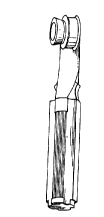
Fig. 1 shows the tool seen obli~uely from the side,Fig. 2 shows the tool handle seen from the front side with
the pressure wheel removed, and
Fig. 3 shows the pressure wheel demounted from the handle.
As shown in fig. 2 the pressure wheel 1 is mounted on the tool_
handle 2 by means of an allchor pin 3. The anchor pin 3 is
maintained on the handle by means of a snap lock 4, the handle
2 being-provided with a t~lreaded hole 5 for receiving the snap
lock screw 4. For receiving the pressure wheel the tool
handle 2 is provided with a guide spindle 6 with a bore 7 for
guiding the anchor pin 3 to the snap lock 4, at which the
anchor pin 3 is shaped wit:h a round-threaded groove at the
snap end for engaging the snap screw 4.
Further, the tool handle 2 is provided with fixation grooves
for engaging an extension rod. Also, the handle is produced
with an impact surface 9 for impact tools, and formed with a
convex curve 12 tapering towards the handle end for the
mounting of the pressure wheel 1. ~-

WO 95/20834 21815 71 PCT/NO95/00018 ~

As shown in fig. 3, the circulnfe~ence of the pressure wheel
is formed with a cylindric groove track 11 delimited on both
sides by a flange to be in contact with the support when
pressure is to be applied on a line for a&esive fixation. ~-
Furthermore the pressure wheel ~1 is also provided with a
frustoconically shaped groove track 10, which at its narrower
end is delimited by a f lange to be in contact with the support
and at its wider end by a transverse surface to be supported
against a wall surface, when pressure is to be applied to a
line for a&esive fixation along a wall corner.
In case a line is to be a&ered to the support by means of a
tool according to the invention, a&esive is first applied to
the line and/or the support. Thereafter the line is placed
with a&erent contact against the support, and a correspond-
ingly adapted groove track 10 or 11 on the pressure wheel 1 of :
the tool is pressed against and guided along the line to
achieve a secure adhesive f ixation on the support .
With a preferred embodiment a suitable double sided a&esive
tape is first applied to the support at the mounting area.
Af ter removing the cover sheet at the top side of the a&esive
tape, said line or cable is placed at the uncovered a&esive
surface and pressed against the same for good a&esive
fixation~by means of the tool according to the invention, as
described above.

Representative Drawing
A single figure which represents the drawing illustrating the invention.
Administrative Status

For a clearer understanding of the status of the application/patent presented on this page, the site Disclaimer , as well as the definitions for Patent , Administrative Status , Maintenance Fee  and Payment History  should be consulted.

Administrative Status

Title Date
Forecasted Issue Date 1999-08-24
(86) PCT Filing Date 1995-01-25
(87) PCT Publication Date 1995-08-03
(85) National Entry 1996-07-18
Examination Requested 1996-07-18
(45) Issued 1999-08-24
Deemed Expired 2004-01-26

Abandonment History

There is no abandonment history.

Payment History

Fee Type Anniversary Year Due Date Amount Paid Paid Date
Request for Examination $200.00 1996-07-18
Application Fee $0.00 1996-07-18
Maintenance Fee - Application - New Act 2 1997-01-27 $50.00 1997-01-10
Maintenance Fee - Application - New Act 3 1998-01-26 $50.00 1998-01-12
Maintenance Fee - Application - New Act 4 1999-01-25 $50.00 1999-01-11
Final Fee $150.00 1999-05-17
Maintenance Fee - Patent - New Act 5 2000-01-25 $75.00 2000-01-25
Maintenance Fee - Patent - New Act 6 2001-01-25 $75.00 2001-01-22
Maintenance Fee - Patent - New Act 7 2002-01-25 $75.00 2002-01-15
Owners on Record

Note: Records showing the ownership history in alphabetical order.

Current Owners on Record
HAGLUND, FINN AGNAR
Past Owners on Record
None
Past Owners that do not appear in the "Owners on Record" listing will appear in other documentation within the application.
Documents

To view selected files, please enter reCAPTCHA code :


To view images, click a link in the Document Description column. To download the documents, select one or more checkboxes in the first column and then click the "Download Selected in PDF format (Zip Archive)" or the "Download Selected as Single PDF" button.

List of published and non-published patent-specific documents on the CPD .

If you have any difficulty accessing content, you can call the Client Service Centre at 1-866-997-1936 or send them an e-mail at CIPO Client Service Centre.


Document
Description 
Date
(yyyy-mm-dd) 
Number of pages   Size of Image (KB) 
Representative Drawing 1999-08-17 1 3
Cover Page 1996-10-21 1 10
Abstract 1995-08-03 1 36
Description 1995-08-03 4 130
Claims 1995-08-03 2 45
Drawings 1995-08-03 1 10
Cover Page 1999-08-17 1 61
Representative Drawing 1997-07-02 1 4
Assignment 1996-07-18 6 201
PCT 1996-07-18 6 215
Correspondence 1999-05-17 2 45
Fees 2002-01-15 1 27
Fees 1999-01-11 1 32
Fees 2000-01-25 1 29
Fees 2001-01-22 1 29
Fees 1998-01-12 1 32
Fees 1997-01-10 1 45